Komatsu PC200-8M0,PC200LC-8M0,PC200-8M1 Excavator Shop Manual PDF
$36.95
Komatsu PC200-8M0,PC200LC-8M0,PC200-8M1 Hydraulic Excavator Shop Manual SENC0010-00 – PDF DOWNLOAD
- PC200-M0- C10001- C19999C20000- and up
- PC200-M1- C24001- and up
Description
Komatsu PC200-8M0,PC200LC-8M0,PC200-8M1 Hydraulic Excavator Shop Manual SENC0010-00 – PDF DOWNLOAD
FILE DETAILS:
Komatsu PC200-8M0,PC200LC-8M0,PC200-8M1 Hydraulic Excavator Shop Manual SENC0010-00 – PDF DOWNLOAD
Language : English
Pages : 1565
Downloadable : Yes
File Type : PDF
IMAGES PREVIEW OF THE MANUAL:
TABLE OF CONTENTS:
Komatsu PC200-8M0,PC200LC-8M0,PC200-8M1 Hydraulic Excavator Shop Manual SENC0010-00 – PDF DOWNLOAD
- PC200-M0- C10001- C19999C20000- and up
- PC200-M1- C24001- and up
00 Index and foreword 2
100 Index 2
Composition of shop manual . 3
Table of contents 5
200 Foreword and general information . 16
Foreword, safety and general information . 17
How to read the shop manual 24
Explanation of terms for maintenance standard 26
Handling equipment of fuel system devices 28
Handling of intake system parts 29
Handling of hydraulic equipment 30
Method of disconnecting and connecting of push-pull type coupler . 32
Handling of electrical equipment . 35
How to read electric wire code . 44
Precautions when performing operation 47
Practical use of KOMTRAX . 50
Standard tightening torque table . 51
List of abbreviation . 55
Conversion table . 60
01 Specification . 66
100 Specification and technical data . 66
Specification dimension drawings . 67
Working range diagram 68
Specifications . 69
Weight table . 73
Table of fuel, coolant and lubricants 77
10 Structure, function and maintenance standard 80
100 Engine and cooling system 80
Engine related parts . 81
Radiator, oil cooler, aftercooler and fuel cooler 82
200 Power train 84
Power train 85
Final drive 87
Swing machinery 91
Swing circle . 95
300 Undercarriage and frame 98
Track frame and recoil spring 99
Idler 101
Carrier roller . 103
Track roller . 104
Track shoe . 105
401 Hydraulic system, Part 1 . 112
Hydraulic equipment layout drawing . 113
Hydraulic tank and filter 115
Hydraulic pump . 117
Pilot oil filter . 139
402 Hydraulic system, Part 2 . 142
Control valve 143
CLSS . 154
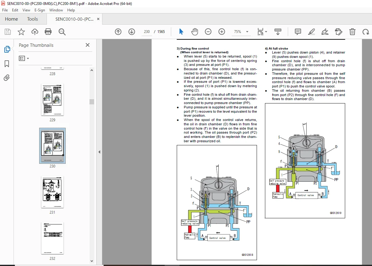
Functions and operation by valve . 158
403 Hydraulic system, Part 3 . 200
Swing motor 201
Center swivel joint 209
Travel motor . 211
PPC valve 221
Valve control 241
Solenoid valve . 243
PPC accumulator 245
Return oil filter 246
Return oil filter with clogging sensor . 247
Attachment circuit selector valve 249
Hydraulic cylinder . 251
500 Work equipment . 256
Work equipment . 257
Dimensions of arm 265
Dimensions of bucket . 267
600 Electrical system 270
Engine control . 271
Electrical control system 281
Machine monitor system . 304
Sensor . 325
KOMTRAX system . 329
Clogging detection system of additional filter for breaker . 332
20 Standard value table 334
100 Standard service value table . 334
Standard value table for engine related parts 335
Standard value table for chassis related parts . 337
30 Testing and adjusting . 356
101 Testing and adjusting, Part 1 356
Tools for testing, adjusting, and troubleshooting 358
Sketch of special tool . 362
Testing engine speed . 363
Testing intake air pressure (boost pressure) . 364
Testing exhaust gas color 365
Adjusting valve clearance 366
Testing compression pressure . 368
Testing blowby pressure 371
Testing engine oil pressure 372
Handling fuel system parts . 373
Releasing residual pressure from fuel system . 373
Testing fuel pressure 374
Handling reduced cylinder mode operation . 377
Handling no-injection cranking operation . 377
Testing fuel discharge, return and leak amount . 378
Bleeding air from fuel circuit . 381
Testing fuel circuit for leakage . 382
Handling controller high voltage circuit . 383
Testing and adjusting air conditioner compressor belt tension 384
Replacing alternator belt 385
Testing swing circle bearing clearance . 386
Testing and adjusting track tension 387
Testing and adjusting oil pressure in work equipment, swing, and travel circuits . 389
Testing control circuit source pressure 392
Testing and adjusting oil pressure in pump PC control circuit 393
Testing and adjusting oil pressure in pump LS control circuit 396
Testing solenoid valve output pressure . 401
Testing PPC valve output pressure 404
Adjusting play of work equipment and swing PPC valves 406
Testing parts which cause hydraulic drift of work equipment 407
Releasing remaining pressure from hydraulic circuit 409
Testing oil leakage 410
Bleeding air from each part 413
Testing cab tipping stopper 415
Adjusting mirrors 416
Installation and adjustment of mirrors . 417
Angle adjustment of rear view camera . 420
102 Testing and adjusting, Part 2 424
Special functions of machine monitor . 425
103 Testing and adjusting, Part 3 476
Handling voltage circuit of engine controller 477
Preparation work for troubleshooting of electrical system 478
Procedure for testing diodes . 483
Handling battery disconnect switch . 484
Pm Clinic service 485
40 Troubleshooting . 496
100 Failure code table and fuse locations 496
Failure codes table 497
Fuse locations . 503
200 General Information on troubleshooting . 506
Symptom and troubleshooting numbers 507
Sequence of events in troubleshooting 509
Checks before troubleshooting 511
Classification and procedures for troubleshooting 513
Symptom and troubleshooting numbers 515
Information in troubleshooting table . 517
Connector/electrical wiring connection table . 519
Connector list and layout 549
Connection table for connector pin numbers . 559
T- branch box and T- branch adapter table 595
Troubleshooting method for open circuit in wiring harness of pressure sensor system 598
301 Troubleshooting by failure code, Part 1 602
Failure code [879AKA] 604
Failure code [879AKB] 604
Failure code [879BKA] 604
Failure code [879BKB] 604
Failure code [879CKA] 604
Failure code [879CKB] 604
Failure code [879DKZ] 605
Failure code [879EMC] 605
Failure code [879FMC] 605
Failure code [879GKX] 605
Failure code [989L00] 606
Failure code [989M00] 607
Failure code [989N00] 608
Failure code [AA10NX] 609
Failure code [AB00KE] 611
Failure code [B@BAZG] 614
Failure code [B@BAZK] 615
Failure code [B@BCNS] 617
Failure code [B@BCZK] 618
Failure code [B@HANS] 620
Failure code [CA111] . 621
Failure code [CA115] . 622
Failure code [CA122] . 623
Failure code [CA123] . 626
Failure code [CA131] . 629
Failure code [CA132] . 632
Failure code [CA144] . 635
Failure code [CA145] . 638
Failure code [CA153] . 641
Failure code [CA154] . 644
Failure code [CA155] . 647
Failure code [CA187] . 648
Failure code [CA221] . 650
Failure code [CA222] . 653
Failure code [CA227] . 656
Failure code [CA234] . 657
Failure code [CA238] . 658
Failure code [CA271] . 660
Failure code [CA272] . 662
302 Troubleshooting by failure code, Part 2 666
Failure code [CA322] . 668
Failure code [CA323] . 671
Failure code [CA324] . 674
Failure code [CA325] . 677
Failure code [CA331] . 680
Failure code [CA332] . 683
Failure code [CA342] . 686
Failure code [CA351] . 687
Failure code [CA352] . 688
Failure code [CA386] . 690
Failure code [CA428] . 691
Failure code [CA429] . 693
Failure code [CA435] . 695
Failure code [CA441] . 697
Failure code [CA442] . 700
Failure code [CA449] . 701
Failure code [CA451] . 703
Failure code [CA452] . 706
Failure code [CA488] . 709
Failure code [CA553] . 710
Failure code [CA559] . 711
Failure code [CA689] . 713
Failure code [CA731] . 716
Failure code [CA757] . 719
Failure code [CA778] . 720
Failure code [CA2185] 725
Failure code [CA2186] 728
Failure code [CA2249] 730
Failure code [CA2311] 731
Failure code [CA2555] 732
Failure code [CA2556] 735
303 Troubleshooting by failure code, Part 3 740
Failure code [D110KB] 743
Failure code [D19JKZ] 745
Failure code [D811MC] 748
Failure code [D862KA] 749
Failure code [D8AQKR] 750
Failure code [DA22KK] 753
Failure code [DA25KP] 756
Failure code [DA26KP] 759
Failure code [DA29KQ] 762
Failure code [DA29KQ] 765
Failure code [DA2QKR] 767
Failure code [DAF0MB] 770
Failure code [DAF0MC] 770
Failure code [DAF8KB] 771
Failure code [DAF9KQ] 773
Failure code [DAFGMC] 774
Failure code [DAFQKR] 775
Failure code [DAZ9KQ] 776
Failure code [DAZQKR] 777
Failure code [DB2QKR] 778
Failure code [DGH2KB] 784
Failure code [DHA4KA] 786
Failure code [DHPAMA] 787
Failure code [DHPBMA] 790
304 Troubleshooting by failure code, Part 4 794
Failure code [DHS3MA] 797
Failure code [DHS4MA] 800
Failure code [DHS8MA] 803
Failure code [DHS9MA] 806
Failure code [DHSAMA] 809
Failure code [DHSBMA] 812
Failure code [DHSCMA] 815
Failure code [DHSDMA] 818
Failure code [DHSFMA] 821
Failure code [DHSGMA] 824
Failure code [DHSHMA] 827
Failure code [DHSJMA] 830
Failure code [DHX1MA] 833
Failure code [DR21KX] 834
Failure code [DR31KX] 836
Failure code [DV20KB] 837
Failure code [DW43KA] 839
Failure code [DW43KB] 841
Failure code [DW45KA] 843
Failure code [DW45KB] 846
Failure code [DW91KA] 849
Failure code [DW91KB] 851
305 Troubleshooting by failure code, Part 5 854
Failure code [DWA2KA] 857
Failure code [DWA2KB] 859
Failure code [DWK0KA] 861
Failure code [DWK0KB] 863
Failure code [DWK2KA] 865
Failure code [DWK2KB] 867
Failure code [DXA8KA] 869
Failure code [DXA8KB] 872
Failure code [DXA9KA] 875
Failure code [DXA9KB] 878
Failure code [DXE0KA] 881
Failure code [DXE0KB] 883
Failure code [DXE4KA] 885
Failure code [DXE4KB] 887
Failure code [DXE5KA] 889
Failure code [DXE5KB] 891
Failure code [DXE6KA] 893
Failure code [DXE6KB] 895
Failure code [DY20KA] 897
Failure code [DY20MA] 900
Failure code [DY2CKB] 903
Failure code [DY2DKB] 906
Failure code [DY2EKB] 908
400 Troubleshooting of electrical system (E-mode) 912
Before troubleshooting for electrical system . 914
Information described in troubleshooting table . 916
E-1 Engine does not start (engine does not rotate) . 918
E-2 Preheating system does not work 927
E-3 Machine monitor displays nothing when starting switch is turned to ON position . 933
E-4 When starting switch is turned to ON position (with engine stopped), basic check items light up 936
E-5 Caution item lights up while the engine is running . 937
E-6 Caution item lights up while the engine is running . 942
E-7 Fuel gauge does not indicate correct level . 945
E-8 Engine coolant temperature gauge does not indicate correct temperature . 948
E-9 Hydraulic oil temperature gauge does not indicate correct temperature 950
E-10 Contents of display on machine monitor are different from actual machine model 953
E-11 Some areas of machine monitor screen are not displayed 955
E-12 Function switch does not work . 955
E-13 Automatic warm-up system does not work (in cold weather) 956
E-14 Auto-deceleration function does not work properly . 958
E-15 Working mode does not change 960
E-16 Travel speed does not change 961
E-17 Alarm buzzer does not stop sounding . 963
E-18 Service meter is not displayed while starting switch is in OFF position . 963
E-19 Service mode cannot be selected . 964
E-20 All work equipment, swing and travel do not work, or lock is not available 965
E-21 Swing parking brake does not work properly 968
E-22 One-touch power maximizing function does not work properly 972
E-23 Travel alarm does not sound or does not stop sounding . 975
E-24 Horn does not sound or does not stop sounding . 977
E-25 Wiper or window washer does not operate . 981
E-26 “Boom LOWER” is not displayed correctly via monitoring function . 984
E-27 “Arm OUT” is not displayed correctly via monitoring function 984
E-28 “Arm IN” is not displayed correctly via monitoring function . 985
E-29 “Boom RAISE” is not displayed correctly via monitoring function . 985
E-30 “Bucket CURL” is not displayed correctly via monitoring function 985
E-31 “Bucket DUMP” is not displayed correctly via monitoring function 986
E-32 “Swing” is not displayed correctly via monitoring function 986
E-33 “Travel” is not displayed correctly via monitoring function . 986
E-34 “Service” is not displayed correctly via monitoring function 987
E-35 Attachment hydraulic circuit cannot be changed 990
E-36 KOMTRAX system does not operate normally 991
E-37 Breaker clogging caution lamp lights up when breaker is not used 993
500 Troubleshooting of hydraulic and mechanical system (H-mode) 996
System diagram of hydraulic and mechanical system 999
Failure mode and cause table .1001
Information in troubleshooting table .1003
H-1 All work equipment, swing and travel speed are all slow, or there is no force 1004
H-2 Engine speed drops significantly or engine stalls 1007
H-3 All work equipment, swing and travel do not work .1009
H-4 Unusual noise is heard from the vicinity of the hydraulic pump .1010
H-5 Fine control performance or response is poor .1011
H-6 Boom speed is low or power is insufficient .1012
H-7 Arm speed is low or power is insufficient 1016
H-8 Bucket speed is low or power is insufficient .1020
H-9 Work equipment does not move in single operation .1022
H-10 Hydraulic drift of work equipment is large 1023
H-11 Time lag of work equipment is large .1027
H-12 When certain work equipment is relieved hydraulically, other work equipment moves .1028
H-13 One-touch power maximization function does not work .1029
H-14 When combining operations of work equipment, equipment subject to heavier loads moves slower 1030
H-15 Boom RAISE is slow in Swing + Boom RAISE operation 1031
H-16 When combining swing and travel operations, travel speed drops significantly 1032
H-17 Travel deviation is detected 1033
H-18 Travel speed is slow 1035
H-19 Machine does not steer well or steering power is low 1038
H-20 Travel speed does not change, or travel speed is too slow or too fast .1042
H-21 One track does not move .1044
H-22 Machine does not swing 1046
H-23 Swing acceleration or swing speed is low 1049
H-24 Upper structure overruns excessively when it stops swinging .1052
H-25 Shock is significant when upper structure stops swinging 1055
H-26 An unusual loud noise is heard when the upper structure stops swinging 1056
H-27 Swing drift on a slope is significant .1057
H-28 Attachment circuit cannot be changed 1060
H-29 Oil flow in the attachment circuit cannot be changed 1061
600 Troubleshooting of engine (S-mode) .1064
Method of using troubleshooting chart 1065
S-1 Startability is poor .1069
S-2 Engine does not start 1070
S-3 Engine does not pick up smoothly .1073
S-4 Engine stops during operation 1074
S-5 Engine runs rough or is unstable .1075
S-6 Engine lacks power .1076
S-7 Exhaust smoke is black (incomplete combustion) .1077
S-8 Oil consumption is excessive (or exhaust smoke is blue) 1078
S-9 Oil becomes contaminated early .1079
S-10 Fuel consumption is excessive .1080
S-11 Oil is in coolant (or coolant spurts or coolant level goes down) 1081
S-12 Oil pressure drops 1082
S-13 Oil level rises (coolant or fuel in oil) 1083
S-14 Coolant temperature rises too high (overheating) 1084
S-15 Unusual noise is made .1085
S-16 Vibration is excessive 1086
50 Disassembly and assembly 1088
100 General information on disassembly and assembly 1088
How to read this manual 1089
Coating materials list .1091
Special tools list .1094
Sketches of special tools 1099
200 Engine and cooling system 1104
Removal and installation of fuel supply pump assembly 1105
Removal and installation of fuel injector assembly .1112
Removal and installation of engine front oil seal 1122
Removal and installation of engine rear oil seal .1129
Removal and installation of cylinder head assembly .1134
Removal and installation of radiator assembly 1155
Removal and installation of hydraulic oil cooler assembly 1160
Removal and installation of aftercooler assembly .1165
Removal and installation of fuel cooler assembly .1170
Removal and installation of engine and hydraulic pump assembly .1173
300 Power train 1196
Removal and installation of final drive assembly .1197
Disassembly and assembly of final drive assembly .1202
Removal and installation of swing motor and swing machinery assembly .1222
Disassembly and assembly of swing motor and swing machinery assembly .1228
Removal and installation of swing circle assembly 1240
400 Undercarriage and frame 1244
Disassembly and assembly of carrier roller assembly 1245
Disassembly and assembly of track roller assembly 1249
Removal and installation of idler and idler cushion assembly .1252
Disassembly and assembly of idler 1255
Disassembly and assembly of idler cushion 1260
Removal and installation of sprocket .1263
Separation and connection of track assembly 1265
Removal and installation of revolving frame assembly .1271
Removal and installation of counterweight assembly .1278
500 Hydraulic system .1284
Removal and installation of center swivel joint assembly .1285
Disassembly and assembly of center swivel joint assembly .1292
Removal and installation of hydraulic tank assembly 1294
Removal and installation of control valve assembly .1304
Disassembly and assembly of control valve 1321
Removal and installation of hydraulic pump assembly 1327
Removal and installation of hydraulic pump input shaft oil seal 1337
Disassembly and assembly of work equipment PPC valve assembly 1338
Disassembly and assembly of travel PPC valve .1340
Disassembly and assembly of work equipment cylinder 1342
600 Work equipment .1350
Removal and installation of work equipment assembly 1351
700 Cab and its attachments 1358
Removal and installation of operator’s cab assembly 1359
Removal and installation of operator’s cab glass (adhered window glass) 1368
Removal and installation of front window assembly 1381
Removal and installation of floor frame assembly .1391
Removal and installation of air conditioner unit assembly 1401
800 Electrical system 1414
Removal and installation of machine monitor assembly .1415
Removal and installation of engine controller assembly .1422
Removal and installation of pump controller assembly .1426
Removal and installation of KOMTRAX terminal assembly 1431
80 Appendix 1438
100 Air conditioner 1438
Precautions for refrigerant 1440
Air conditioner component 1441
Configuration and function of refrigeration cycle 1443
Outline of refrigeration cycle .1444
Air conditioner unit .1446
Air conditioner controller .1452
Compressor .1453
Condenser and Modulator 1454
Sensor .1455
Procedure for testing and troubleshooting 1457
Circuit diagram and arrangement of connector pins 1459
System diagram .1461
Parts and connectors layout 1463
Testing air leakage (duct) .1466
Testing with self-diagnosis function .1468
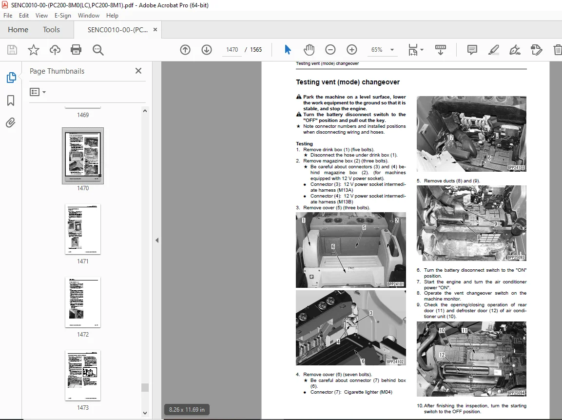
Testing vent (mode) changeover .1470
Testing FRESH/RECIRC air changeover 1471
Testing sunlight sensor 1472
Testing (dual) pressure switch for refrigerant .1473
Testing relays .1474
Troubleshooting chart 1 1475
Troubleshooting chart 2 1477
Information in troubleshooting table .1479
Failure code list related to air conditioner .1480
Failure code [879AKA] A/C Inner sensor Open Circuit 1481
Failure code [879AKB] A/C Inner sensor Short Circuit .1482
Failure code [879BKA] A/C Outer sensor Open Circuit 1483
Failure code [879BKB] A/C Outer sensor Short Circuit .1485
Failure code [879CKA] Ventilating sensor Open Circuit 1487
Failure code [879CKB] Ventilating sensor Short Circuit .1488
Failure code [879DKZ] Sunlight sensor Open or Short Circuit 1489
Failure code [879EMC] Ventilating Damper Abnormality .1491
Failure code [879FMC] Air Mix Damper Abnormality .1492
Failure code [879GKX] Refrigerant Abnormality 1493
Troubleshooting for power supply and CAN communication system (Air conditioner does not operate) .1495
Troubleshooting for compressor and refrigerant system (Air is not cooled) 1497
Troubleshooting for blower motor system (No air comes out or air flow is abnormal) .1500
Troubleshooting for FRESH/RECIRC air changeover 1502
Troubleshooting with gauge pressure 1504
Connection of service tool .1506
Precautions for disconnecting and connecting air conditioner piping 1508
Handling of compressor oil .1510
Desiccant replacement procedure 1512
90 Diagrams and drawings .1516
100 Hydraulic diagrams and drawings 1516
Symbols in hydraulic circuit diagram .1517
Hydraulic circuit diagram 1520
200 Electrical diagrams and drawings .1530
Symbols in electric circuit diagram 1531
Electrical circuit diagram .1534
Wiring harness diagram .1544
DESCRIPTION:
Komatsu PC200-8M0,PC200LC-8M0,PC200-8M1 Hydraulic Excavator Shop Manual SENC0010-00 – PDF DOWNLOAD
- PC200-M0- C10001- C19999C20000- and up
- PC200-M1- C24001- and up
How to read the shop manual
Composition of shop manual
This shop manual describes the technical information required for the services performed in a workshop.
The shop manual is divided into the following chapters for the convenience of use.
00. Index and foreword
This section includes the index, foreword, safety and basic information.
01. Specification
This section explains the specifications of the machine.
10. Structure, function and maintenance standard
This section explains the structure, function, and maintenance standard values of each component. The
structure and function sub-section explains the structure and function of each component. It serves not
only to give an understanding of the structure, but also serves as reference material for troubleshooting.
The maintenance standard sub-section explains the criteria and remedies for disassembly and service.
20. Standard value table
The standard values for a new machine and trouble shooting are described. This standard value table is
used for testing and adjusting, and determining a failure at troubleshooting.
30. Testing and adjusting
This section describes the measuring tools and how to measure, and how to adjust various parts. As for
the standard value and failure criterion, see the standard value table.
40. Troubleshooting
This section describes the troubleshooting in a suspected area when a failure occurs and the remedy for
the failure. Troubleshooting is described by each failure mode.
50. Disassembly and assembly
This section explains the procedures for removing, installing, disassembling, and assembling each part
or component and the special tools for the works as well as precautions for doing them safely. In addition,
tightening torque, and quantity and weight of coating material, oil, grease, and coolant required for
the works are also explained.
80. Appendix
The structure and function, testing and adjusting, and troubleshooting for all of the other components or
equipment which can not be separately classified are explained together in the appendix.
90. Diagrams and drawings
This section gives hydraulic circuit diagrams and electrical circuit diagrams.
G.B 30/12/24


