
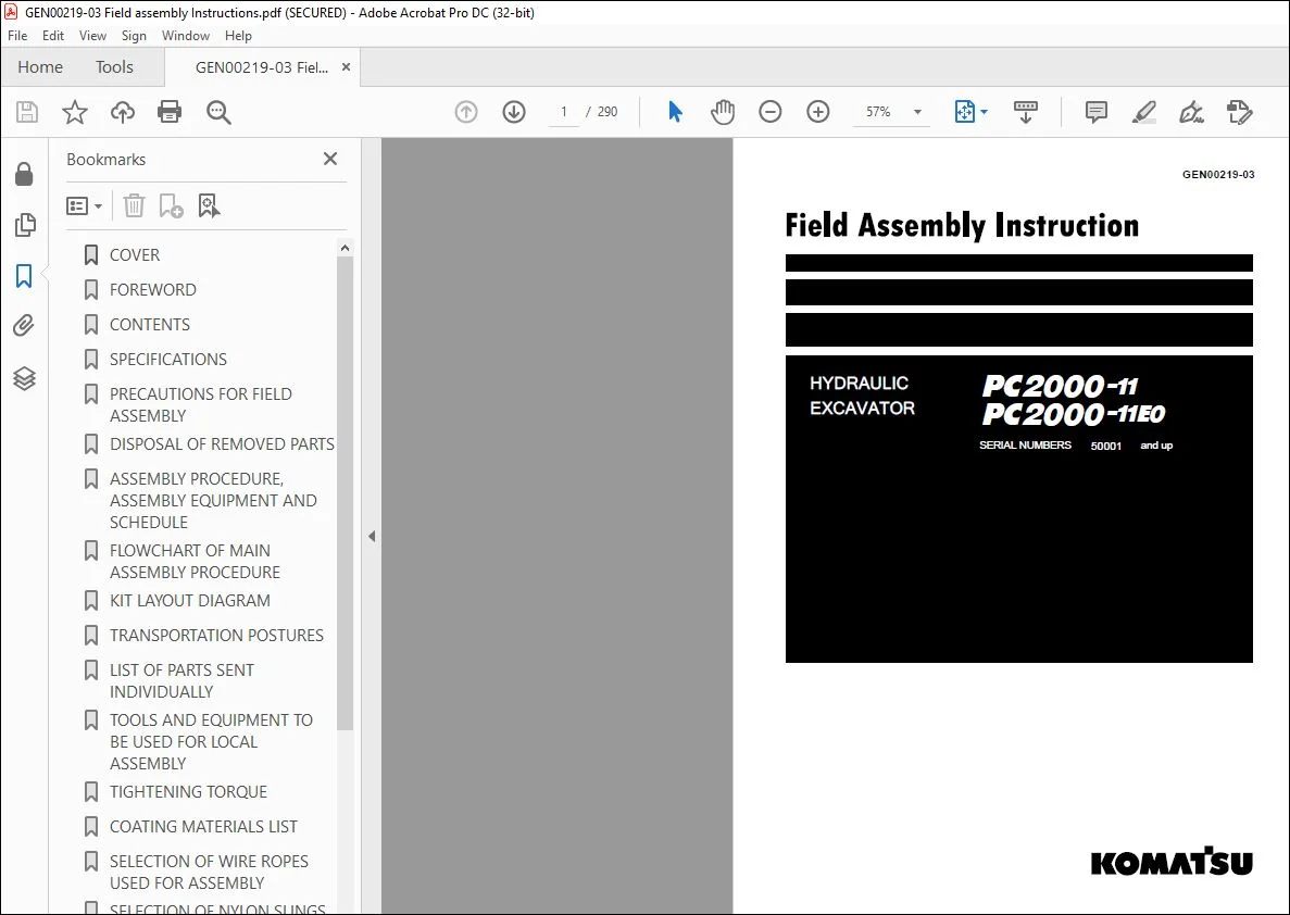
KOMATSU PC2000-11 PC2000-11E0 HYDRAULIC EXCAVATOR FIELD ASSEMBLY INSTRUCTION GEN00219-03 – PDF DOWNLOAD
Original price was: $85.95.$28.95Current price is: $28.95.
KOMATSU PC2000-11 PC2000-11E0 HYDRAULIC EXCAVATOR FIELD ASSEMBLY INSTRUCTION GEN00219-03 – PDF DOWNLOAD
SERIAL NUMBERS 50001 and up
Description
KOMATSU PC2000-11 PC2000-11E0 HYDRAULIC EXCAVATOR FIELD ASSEMBLY INSTRUCTION GEN00219-03 – PDF DOWNLOAD
DESCRIPTION:
KOMATSU PC2000-11 PC2000-11E0 HYDRAULIC EXCAVATOR FIELD ASSEMBLY INSTRUCTION GEN00219-03 – PDF DOWNLOAD
SERIAL NUMBERS 50001 and up
FOREWORD:
- Since this machine is large in size, it is divided into some units to meet
the transportation conditions and regulations applied to the transportation
route when shipped from our factory. - This manual describes how to assemble the units into the complete
machine in the field. We hope that this machine will display its quality
and you will use it safely according to the operation manual. - Many units are large in size and heavy in weight and may be handled
in a dangerous place or posture and many workers may have to work
together to sling them with cranes. - Accordingly, before starting the assembly work, the work supervisor is
required to hold a safety meeting to oblige the workers to put on protective
gear and appoint a work leader and a crane work signal man
and allot roles to all the workers for safe work.
In particular, the above meeting is more important when worker of different
languages and customs work together.
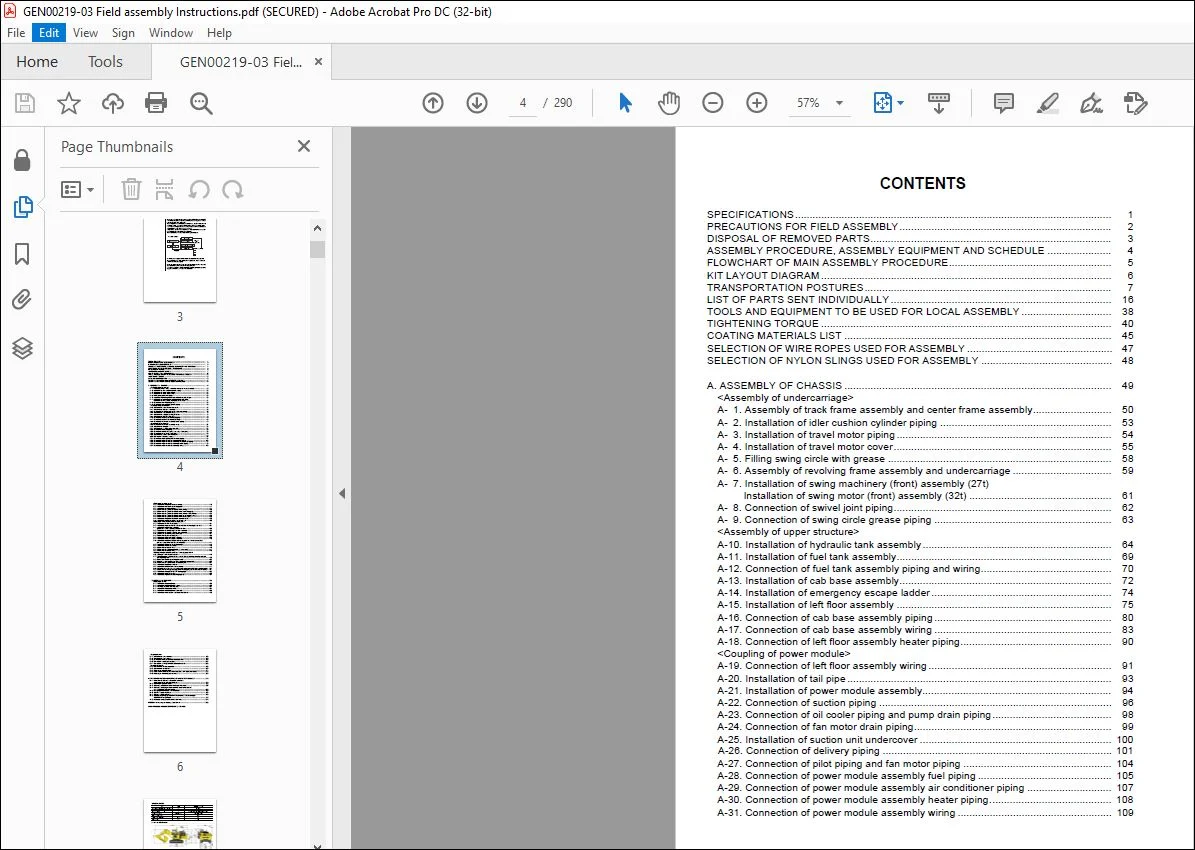
TABLE OF CONTENTS:
KOMATSU PC2000-11 PC2000-11E0 HYDRAULIC EXCAVATOR FIELD ASSEMBLY INSTRUCTION GEN00219-03 – PDF DOWNLOAD
COVER 1
FOREWORD 3
CONTENTS 4
SPECIFICATIONS 7
PRECAUTIONS FOR FIELD ASSEMBLY 8
DISPOSAL OF REMOVED PARTS 9
ASSEMBLY PROCEDURE, ASSEMBLY EQUIPMENT AND SCHEDULE 10
FLOWCHART OF MAIN ASSEMBLY PROCEDURE 11
KIT LAYOUT DIAGRAM 12
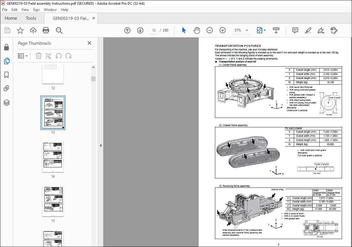
TRANSPORTATION POSTURES 13
LIST OF PARTS SENT INDIVIDUALLY 22
TOOLS AND EQUIPMENT TO BE USED FOR LOCAL ASSEMBLY 44
TIGHTENING TORQUE 46
COATING MATERIALS LIST 51
SELECTION OF WIRE ROPES USED FOR ASSEMBLY 53
SELECTION OF NYLON SLINGS USED FOR ASSEMBLY 54
A ASSEMBLY OF CHASSIS 55
<Assembly of undercarriage> 56
A- 1 Assembly of track frame assembly and center frame assembly 56
A- 2 Installation of idler cushion cylinder piping 59
A- 3 Installation of travel motor piping 60
A- 4 Installation of travel motor cover 61
A- 5 Filling swing circle with grease 64
A- 6 Assembly of revolving frame assembly and undercarriage 65
A- 7 Installation of swing machinery (front) assembly (27t) Installation of swing motor (front) assembly (32t) 67
A- 8 Connection of swivel joint piping 68
A- 9 Connection of swing circle grease piping 69
<Assembly of upper structure> 70
A-10 Installation of hydraulic tank assembly 70
A-11 Installation of fuel tank assembly 75
A-12 Connection of fuel tank assembly piping and wiring 76
A-13 Installation of cab base assembly 78
A-14 Installation of emergency escape ladder 80
A-15 Installation of left floor assembly 81
A-16 Connection of cab base assembly piping 86
A-17 Connection of cab base assembly wiring 89
A-18 Connection of left floor assembly heater piping 96
<Coupling of power module> 97
A-19 Connection of left floor assembly wiring 97
A-20 Installation of tail pipe 99
A-21 Installation of power module assembly 100
A-22 Connection of suction piping 102
A-23 Connection of oil cooler piping and pump drain piping 104
A-24 Connection of fan motor drain piping 105
A-25 Installation of suction unit undercover 106
A-26 Connection of delivery piping 107
A-27 Connection of pilot piping and fan motor piping 110
A-28 Connection of power module assembly fuel piping 111
A-29 Connection of power module assembly air conditioner piping 113
A-30 Connection of power module assembly heater piping 114
A-31 Connection of power module assembly wiring 115
<Coupling of operator’s cab> 119
A-32 Installation of operator’s cab assembly 119
A-33 Installation of rotary lamp (if equipped) 123
A-34 Installation of iridium antenna 125
A-35 Connection of operator’s cab assembly wiring 126
A-36 Connection of operator’s cab assembly hydraulic piping 129
A-37 Connection of operator’s cab assembly window washer hose 131
A-38 Connection of operator’s cab assembly air conditioner piping 132
A-39 Connection of operator’s cab assembly heater piping 134
A-40 Installation of operator’s cab rear floor assembly 135
A-41 Installation of handrail around operator’s cab 136
<Coupling of exterior parts, counterweight, etc > 137
A-42 Installation of track frame ladder 137
A-43 Installation of power module side catwalk assemblies (right and left) 138
A-44 Installation of right floor assembly, grease can cover assembly and center floor 139
A-45 Installation of fuel tank right catwalk assembly 141
A-46 Installation of fuel tank front catwalk assembly 142
A-47 Adjustment of exterior parts clearance 143
A-48 Connection of grease reel piping 144
A-49 Installation of access ladder assembly 145
A-50 Installation of counterweight assembly 146
A-51 Installation of deformation preventing stoppers for catwalk assemblies (left and right) on the side of power module 147
A-52 Installation of handrail on counterweight 148
A-53 Installation of handrail clamps 149
A-54 Connection of fuel cut wire 152
A-55 Connection of drain piping under power module 153
A-56 Connection of battery wiring 154
<Starting of engine and inspection and servicing procedures> 155
A-57 Setting of hydraulic tank strainer 155
A-58 Starting engine, checking oil and coolant levels, bleeding air from each part, and adjusting track 156
A-59 Permanent tightening of swing circle bolt 171
A-60 Parts to be touched up after field assembly (chassis side) 172
A-61 Connection of engine heater connection port 173
A-62 Installation of optional harness 176
A-63 Installation of KomVision and rear lamp 177
A-64 Connection of emergency stop switch (if equipped) (at the right below power module) 186
A-65 Connection of emergency stop switch (if equipped) (at the left side of ladder) 187
A-66 Installation of engine oil and PTO oil pipings 188
A-67 Installation of coolant piping 189
A-68 Installation of guard bracket (if equipped) 190
C ASSEMBLY OF BACKHOE 191
<Coupling of boom> 192
C- 1 Installation of boom cylinder 192
C- 2 Installation of boom cylinder hoses 194
C- 3 Assembly of boom sub assembly 195
C- 4 Installation of boom assembly 200
C- 5 Installation of boom cylinder head side 202
C- 6 Installation of hoses between boom and chassis 204
<Coupling of arm> 205
C- 7 Installation of arm assembly 205
C- 8 Installation of arm cylinder 208
C- 9 Connection of hoses between boom and arm 209
C-10 Connection of auto grease piping 210
C-11 Connection of wiring between boom and chassis 211
<Coupling of bucket> 212
C-12 Installation of bucket assembly 212
C-13 Installation of bucket link 215
C-14 Bleeding air from cylinders 217
C-15 Parts to be touched up after field assembly (work equipment side) 221
C-16 Bleeding air from auto grease circuit 222
M INSPECTION AND SERVICING PROCEDURES AFTER ASSEMBLY 225
M- 1 Inspection of oil levels and coolant levels and using standard of fuel and lubricant 226
M- 2 Flushing of hydraulic circuit 228
M- 3 Releasing residual pressure from hydraulic circuit 237
M- 4 Releasing residual pressure from HIC circuit and check of gas pressure in HIC accumulator 238
M- 5 Charging air conditioner with refrigerant 239
M- 6 Installed angles of mirrors 242
M- 7 Installed angles of lights 245
M-8 Method for starting up KOMTRAX terminal and default setting of KOMTRAX Plus controller 248
M- 9 Method of camera calibration for KomVision 249
PC2000-11 Main pump air bleeding check sheet 262
FIELD ASSEMBLY INSPECTION REPORT (BACKHOE) 263
IMAGES PREVIEW OF THE MANUAL:
Contact us: [email protected]
https://vimeo.com/742916820
PLEASE NOTE:
- This is the same manual used by the dealers to diagnose and troubleshoot your vehicle
- You will be directed to the download page as soon as the purchase is completed. The whole payment and downloading process will take anywhere between 2-5 minutes
- Need any other service / repair / parts manual, please feel free to contact [email protected] . We still have 50,000 manuals unlisted
I.G



