Komatsu PC200LC-8, PC220LC-8 Hydraulic Excavator Shop Manual CEBM000903 – PDF DOWNLOAD
Original price was: $51.95.$28.95Current price is: $28.95.
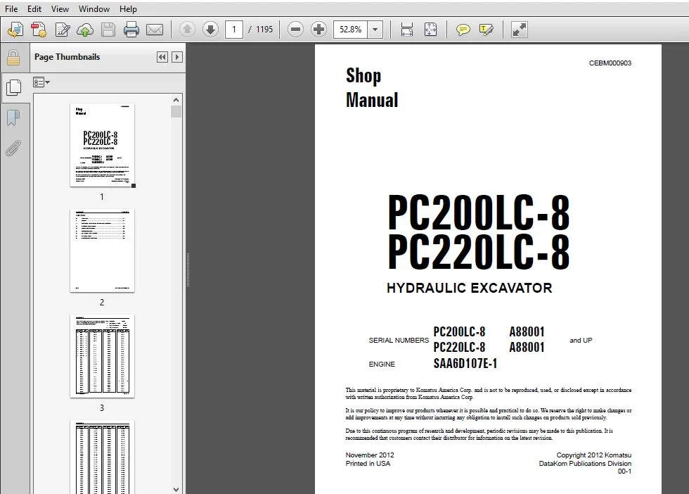
Komatsu PC200LC-8, PC220LC-8 Hydraulic Excavator Shop Manual
SERIAL NUMBERS:
PC200LC-8 A88001 and up
PC220LC-8 A88001 and up
Description
Komatsu PC200LC-8, PC220LC-8 Hydraulic Excavator Shop Manual
FILE DETAILS:
Komatsu PC200LC-8, PC220LC-8 Hydraulic Excavator Shop Manual
Brands: Komatsu
Equipment Type: Hydraulic Excavator
Manuals Type: Shop Manual
Machine Model: PC200LC-8, PC220LC-8
Serial Number: A88001 and up
Book Code: CEBM000903
Language: English
Pages: 1195
File Format: Portable Document Format (PDF)
DESCRIPTION:
Komatsu PC200LC-8, PC220LC-8 Hydraulic Excavator Shop Manual
GENERAL:
- This shop manual has been prepared as an aid to improve the quality of repairs by giving the serviceman an accurate understanding of the product and by showing him the correct way to perform repairs and make judgements. Make sure you understand the contents of this manual and use it to full effect at every opportunity.
- This shop manual mainly contains the necessary technical information for operations performed in a service workshop. For ease of understanding, the manual is divided into the following sections. These sections are further divided into each main group of components.
GENERAL:
This section lists the general machine dimensions, performance specifications, component weights, and fuel, coolant and lubricant specification charts.
STRUCTURE, FUNCTION AND MAINTENANCE STANDARD:
This section explains the structure and function of each component. It serves not only to give an understanding of the structure, but also serves as reference material for troubleshooting. In addition, this section gives the judgement standards when inspecting disassembled parts.
STANDARD VALUE TABLE:
This section explains the standard values for new machine and judgement criteria for testing, adjusting and troubleshooting. This standard value table is used to check the standard values in testing and adjusting and to judge parts in troubleshooting.
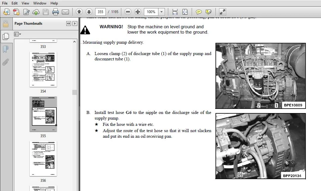
TESTING AND ADJUSTING:
This section explains checks to be made before and after performing repairs, as well as adjustments to be made at completion of the checks and repairs.
TROUBLESHOOTING:
Troubleshooting charts correlating “Problems” to “Causes” are also included in this section.
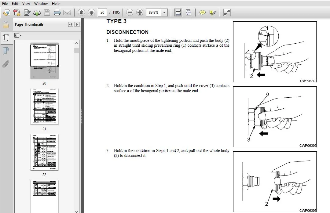
DISASSEMBLY AND ASSEMBLY:
This section explains the order to be followed when removing, installing, disassembling or assembling each component, as well as precautions to be taken for these operations.
AIR CONDITIONING:
This section explains the air conditioning system. The structure, function, maintenance standard, testing, adjusting, troubleshooting, servicing and some disassembly and assembly.
DIAGRAMS AND DRAWINGS:
This section explains the order to be followed when removing, installing, disassembling or assembling each component,
as well as precautions to be taken for these operations.
DIAGRAMS AND SCHEMATICS:
This section has the foldout drawings for the machine.
TABLE OF CONTENTS:
Komatsu PC200LC-8, PC220LC-8 Hydraulic Excavator Shop Manual
CEMB000903 PC200/220LC-8.................................................................................   1
	CONTENTS.............................................................................................   2
	REVISED PAGES........................................................................................   3
	SAFETY...............................................................................................  13
		SAFETY NOTICE....................................................................................  13
			IMPORTANT SAFETY NOTICE......................................................................  13
			GENERAL PRECAUTIONS..........................................................................  13
			PREPARATIONS FOR WORK........................................................................  13
			PRECAUTIONS DURING WORK......................................................................  13
	GENERAL..............................................................................................  15
	HOW TO READ THE SHOP MANUAL..........................................................................  16
		VOLUMES..........................................................................................  16
		DISTRIBUTION AND UPDATING........................................................................  16
		FILING METHOD....................................................................................  16
		REVISED EDITION MARK.............................................................................  16
		REVISIONS........................................................................................  16
		SYMBOLS..........................................................................................  16
	HOISTING INSTRUCTIONS................................................................................  17
		HOISTING.........................................................................................  17
		WIRE ROPES.......................................................................................  17
	PUSH PULL COUPLER....................................................................................  18
		TYPE 1...........................................................................................  18
			DISCONNECTION................................................................................  18
			CONNECTION...................................................................................  18
		TYPE 2...........................................................................................  19
			DISCONNECTION................................................................................  19
			CONNECTION...................................................................................  19
		TYPE 3...........................................................................................  20
			DISCONNECTION................................................................................  20
			CONNECTION...................................................................................  20
	COATING MATERIALS....................................................................................  21
	STANDARD TIGHTENING TORQUE...........................................................................  24
		STANDARD TIGHTENING TORQUE OF BOLTS AND NUTS.....................................................  24
		TIGHTENING TORQUE OF HOSE NUTS...................................................................  25
		TIGHTENING TORQUE OF SPLIT FLANGE BOLTS..........................................................  25
		TIGHTENING TORQUE FOR FLARED NUTS................................................................  25
		TABLE OF TIGHTENING TORQUES FOR O-RING BOSS PIPING JOINTS........................................  26
		TABLE OF TIGHTENING TORQUES FOR O-RING BOSS PLUGS................................................  26
		TIGHTENING TORQUE TABLE FOR HOSES (TAPER SEAL TYPE AND FACE SEAL TYPE)...........................  26
	ELECTRIC WIRE CODE...................................................................................  27
		CLASSIFICATION BY THICKNESS......................................................................  27
		CLASSIFICATION BY COLOR AND CODE.................................................................  27
	CONVERSION TABLES....................................................................................  28
		METHOD OF USING THE CONVERSION TABLE.............................................................  28
01 GENERAL...............................................................................................  35
	SPECIFICATION AND TECHNICAL DATA.....................................................................  36
		Specification Dimension Drawings.................................................................  36
		Working Range Diagram............................................................................  37
		Specifications...................................................................................  38
			PC200LC-8....................................................................................  38
			PC220LC-8....................................................................................  40
		Weight Table.....................................................................................  42
			PC200LC-8....................................................................................  42
			PC220LC-8....................................................................................  44
		Table Of Fuel, Coolant And Lubricants............................................................  46
		Recommended Brands, Recommended Quality For Products Other Than Komatsu Genuine Oil..............  47
10 STRUCTURE, FUNCTION AND MAINTENANCE STANDARD..........................................................  49
	ENGINE AND COOLING SYSTEM............................................................................  53
		Engine Related Parts.............................................................................  53
		Radiator, Oil Cooler, Aftercooler and Fuel Cooler................................................  54
	POWER TRAIN..........................................................................................  55
		Power Train......................................................................................  55
		Final Drive......................................................................................  56
		Swing Machinery..................................................................................  58
			PC200LC-8....................................................................................  58
			PC220LC-8....................................................................................  60
		Swing Circle.....................................................................................  62
			PC200LC-8....................................................................................  62
			PC220LC-8....................................................................................  64
	UNDERCARRIAGE AND FRAME..............................................................................  66
		Track Frame And Recoil Spring....................................................................  66
			Standard Shoe................................................................................  67
		Idler............................................................................................  68
		Carrier Roller...................................................................................  70
		Track Roller.....................................................................................  72
		Track Shoe.......................................................................................  74
			Triple Grouser Shoe..........................................................................  77
	HYDRAULIC SYSTEM.....................................................................................  78
		Hydraulic Equipment Layout Drawing...............................................................  78
		Hydraulic Tank And Filter........................................................................  80
		Hydraulic Pump...................................................................................  82
			Type: HPV95+95...............................................................................  82
			Operation of pump............................................................................  87
			Control of delivery..........................................................................  88
			LS Valve.....................................................................................  89
			PC Valve.....................................................................................  95
			LS (PC)-EPC Valve............................................................................ 102
		Pilot Oil Filter................................................................................. 105
			For breaker.................................................................................. 105
		Control Valve.................................................................................... 107
			Outline...................................................................................... 107
			General View................................................................................. 108
			Sectional View............................................................................... 112
		CLSS............................................................................................. 122
			Outline of CLSS.............................................................................. 122
			LS Differential Pressure and Pump Swash Plate Angle.......................................... 123
		Functions and Operation by Valve................................................................. 126
			Hydraulic Circuit Diagram and the Name of Valves............................................. 126
			Unload Valve................................................................................. 128
			Introduction Of LS Pressure.................................................................. 130
			LS Bypass Plug............................................................................... 131
			Pressure Compensation Valve.................................................................. 132
			Integrated Pressure Compensation Valve....................................................... 133
			Pressure Compensation Valve Inner Shuttle Valve.............................................. 135
			Boom Regeneration Circuit.................................................................... 137
			Arm Regeneration Circuit..................................................................... 139
			Merge-divider Valve.......................................................................... 141
			LS Select Valve.............................................................................. 144
			Self Pressure Reducing Valve................................................................. 145
			Travel Junction Valve........................................................................ 148
			Travel PPC Shuttle Valve..................................................................... 150
			Boom Drift Prevention Valve.................................................................. 153
			Arm Drift Prevention Valve (if equipped)..................................................... 156
			Quick Return Valve........................................................................... 160
			Lift Check Valve............................................................................. 163
			Main Relief Valve............................................................................ 164
			2-stage Safety-suction Valve................................................................. 165
		Swing Motor...................................................................................... 168
			Torque Values................................................................................ 169
			Specifications............................................................................... 169
			Swing Holding Brake.......................................................................... 172
			Relief Valve Portion......................................................................... 173
			Outline...................................................................................... 173
			Reverse Prevention Valve..................................................................... 174
			Center Swivel Joint.......................................................................... 178
			Travel Motor................................................................................. 180
			Operation Of Motor........................................................................... 184
			Operation of Parking Brake................................................................... 186
			Brake Valve.................................................................................. 188
			Operation When Pressurized Oil is Supplied................................................... 188
			Operation of Brake During Traveling Downhill................................................. 189
		PPC Valve........................................................................................ 192
			Work Equipment and Swing PPC Valve........................................................... 192
			Travel PPC Valve............................................................................. 198
			Pressure reducing valve function............................................................. 202
			Travel Signal/steering Function.............................................................. 204
			Service PPC Valve (With EPC Valve)........................................................... 210
			EPC valve.................................................................................... 212
			When Signal Current Is 0..................................................................... 214
			When Signal Current is Very Small............................................................ 214
			When Signal Current Is Maximum............................................................... 215
		Service PPC Valve................................................................................ 216
		Valve Control.................................................................................... 218
			Lever Positions.............................................................................. 219
		Solenoid Valve................................................................................... 220
			When Solenoid is De-energized................................................................ 221
			When Solenoid is Energized................................................................... 222
		PPC Accumulator.................................................................................. 223
			Specifications............................................................................... 223
		CRN (Canadian certified) PPC Accumulator......................................................... 223
		Return Oil Filter................................................................................ 224
		Attachment Circuit Selector Valve................................................................ 225
			When Attachment Other Than Breaker is Installed.............................................. 226
			When Breaker is Installed.................................................................... 226
		Hydraulic Cylinder............................................................................... 228
			PC200LC-8.................................................................................... 228
			PC220LC-8.................................................................................... 230
	WORK EQUIPMENT....................................................................................... 232
		Dimensions of Components......................................................................... 232
			PC200LC-8.................................................................................... 233
			PC220LC-8.................................................................................... 234
	CAB AND ITS ATTACHMENTS.............................................................................. 240
		Air Conditioner Piping........................................................................... 240
	ELECTRICAL SYSTEM.................................................................................... 241
		Engine Control................................................................................... 241
			Operation of system.......................................................................... 241
		Component........................................................................................ 242
			Fuel Control Dial............................................................................ 242
			Engine Controller............................................................................ 243
			Coolant Temperature Sensor................................................................... 246
			Oil Pressure Switch.......................................................................... 246
			Rotation Sensor.............................................................................. 247
			Boost Pressure and Temperature Sensor........................................................ 247
			WIF (Water-in-fuel Detection) Sensor......................................................... 248
			Engine Oil Level Sensor...................................................................... 248
		Electrical Control System........................................................................ 250
			Machine Control System Diagram............................................................... 250
			Function..................................................................................... 263
	MONITOR SYSTEM....................................................................................... 274
		Machine Monitor.................................................................................. 275
			Input And Output Signals..................................................................... 276
		Monitor Control, Display Portion................................................................. 278
			Precautions on the Machine Monitor Display................................................... 279
			Monitor Items and Display.................................................................... 280
		Switches......................................................................................... 284
			Buzzer Cancel Switch......................................................................... 284
			Auto-deceleration Switch..................................................................... 284
			Guidance Icon And Function Switch............................................................ 284
			Working Mode Selector Switch................................................................. 286
			Travel Speed Selector Switch................................................................. 286
			Window Washer Switch......................................................................... 287
			Wiper Switch................................................................................. 287
			Air Conditioner Control Switch............................................................... 287
			Camera Screen Display Function............................................................... 288
			Service Meter/Time Selector Function......................................................... 289
			Maintenance Function......................................................................... 289
			User Mode.................................................................................... 291
			Breaker/Attachment Setting................................................................... 291
			Changing Breaker Mode Setting................................................................ 292
			Changing Attachment Mode Setting............................................................. 294
			Message Display.............................................................................. 295
			Screen Adjustment............................................................................ 296
			Clock Adjustment............................................................................. 296
			Language Setting............................................................................. 297
			Economy Mode Adjustment...................................................................... 297
			Idle Stop Guidance Function.................................................................. 298
			Service Meter Check Function................................................................. 298
			Display LCD Check Function................................................................... 298
			User Code/Failure Code Display Function...................................................... 299
	SENSOR............................................................................................... 300
		Fuel Level Sensor................................................................................ 300
		Air Cleaner Clogging Sensor...................................................................... 301
		Coolant Level Sensor............................................................................. 301
	KOMTRAX TERMINAL SYSTEM.............................................................................. 302
		KOMTRAX Communication ORBCOMM.................................................................... 303
			TH300........................................................................................ 303
			Input And Output Signals..................................................................... 303
20 STANDARD VALUE TABLES................................................................................. 305
	STANDARD SERVICE VALUE TABLE......................................................................... 307
		Standard Service Value Table for Engine.......................................................... 307
			PC200LC-8.................................................................................... 307
			PC220LC-8.................................................................................... 308
		Standard Value Table for Chassis Related Parts................................................... 309
			PC200LC-8.................................................................................... 309
			PC220LC-8.................................................................................... 316
		Machine Position for Measurement (For Both Models)............................................... 323
			Control Valve: Spool Stroke.................................................................. 323
			Swing 1: Swing Brake Angle, Time Taken To Start Swing, Time Taken To Swing................... 323
			Swing 2: Hydraulic Drift Of Swing............................................................ 323
			Travel 1: Travel Speed (Without Load)........................................................ 323
			Travel 2: Travel Speed (Actual Run), Travel Deviation........................................ 324
			Travel 3: Travel Deviation................................................................... 324
			Travel 4: Hydraulic Drift Of Travel.......................................................... 324
			Work Equipment 1: Hydraulic Drift Of Work Equipment.......................................... 324
			Work Equipment 2: Boom Speed................................................................. 325
			Work Equipment 3: Arm Speed.................................................................. 325
			Work Equipment 4: Bucket Speed............................................................... 325
			Work Equipment 5: Boom Time Lag.............................................................. 325
			Work Equipment 6: Arm Time Lag............................................................... 326
			Work Equipment 7: Bucket Time Lag............................................................ 326
			Work Equipment 8: Characteristics Of PC Flow Control Valve................................... 326
30 TESTING AND ADJUSTING................................................................................. 327
	SPECIAL TOOL LIST.................................................................................... 330
		Sketch Of Special Tool........................................................................... 333
	ENGINE COMPONENTS.................................................................................... 334
		Determining A Defective Cylinder................................................................. 334
			Procedures................................................................................... 334
			Determining Cylinder Group................................................................... 334
			Isolating the Defective Cylinder............................................................. 334
		Water Pump Leakage............................................................................... 335
		Engine Speed..................................................................................... 340
		Intake Air Pressure (Boost Pressure)............................................................. 342
		Exhaust Gas Color................................................................................ 343
		Valve Clearance.................................................................................. 345
		Compression Pressure............................................................................. 347
		Blow-by Pressure................................................................................. 349
		Engine Oil Pressure.............................................................................. 350
		Handling Fuel System Parts....................................................................... 351
			Releasing Residual Pressure From Fuel System................................................. 351
		Fuel Pressure.................................................................................... 352
		Fuel Return Rate And Leakage..................................................................... 355
		Bleeding Air From Fuel Circuit................................................................... 360
		Fuel Circuit - Checking For Leakage.............................................................. 361
	AIR CONDITIONER COMPRESSOR BELT TENSION.............................................................. 362
		Checking......................................................................................... 362
		Adjusting........................................................................................ 362
	FAN BELT............................................................................................. 363
	SWING CIRCLE BEARING CLEARANCE....................................................................... 364
	TRACK SHOE TENSION................................................................................... 366
		Checking......................................................................................... 366
		Adjusting........................................................................................ 366
	OIL PRESSURE IN WORK EQUIPMENT, SWING, AND TRAVEL CIRCUITS........................................... 368
		Measuring........................................................................................ 368
		Adjusting........................................................................................ 371
	CONTROL CIRCUIT BASIC PRESSURE....................................................................... 373
	OIL PRESSURE IN PUMP PC CONTROL CIRCUIT.............................................................. 375
		Measuring........................................................................................ 375
		Adjusting........................................................................................ 377
			Pump PC Valve................................................................................ 377
	OIL PRESSURE IN PUMP LS CONTROL CIRCUIT.............................................................. 378
		Measuring........................................................................................ 378
		Adjusting........................................................................................ 382
			LS valve..................................................................................... 382
	SOLENOID VALVE OUTPUT PRESSURE....................................................................... 383
	PPC VALVE OUTPUT PRESSURE............................................................................ 386
		Connecting Points Of PPC Piping.................................................................. 386
		Adjusting Play of Work Equipment and Swing PPC Valves............................................ 388
	WORK EQUIPMENT HYDRAULIC DRIFT....................................................................... 389
	RELEASING RESIDUAL PRESSURE FROM HYDRAULIC CIRCUIT................................................... 391
	OIL LEAKAGE.......................................................................................... 392
	BLEEDING AIR FROM EACH PART.......................................................................... 395
	CAB TIPPING STOPPER.................................................................................. 397
	MIRRORS.............................................................................................. 398
	REAR VIEW CAMERA..................................................................................... 401
		Angle Adjustment................................................................................. 401
	MACHINE MONITOR SPECIAL FUNCTIONS.................................................................... 403
		Air Conditioner Specification.................................................................... 403
		Upper Section of Machine Monitor................................................................. 404
			Display Section.............................................................................. 404
			Switch Section............................................................................... 404
		Lower Section Of Machine Monitor................................................................. 404
			Switch Section............................................................................... 404
		Ordinary Functions and Special Functions of Machine Monitor...................................... 405
		Operator Mode (Outline).......................................................................... 407
			Display of KOMATSU Logo...................................................................... 408
			Display of Inputting Password................................................................ 408
			Display of Check of Breaker Mode............................................................. 408
			Display of Check Before Starting............................................................. 409
			Display of Warning After Check Before Starting............................................... 409
			Display of Ending of Maintenance Interval.................................................... 409
			Display of Check of Working Mode and Travel Speed............................................ 409
			Display of Ordinary Screen................................................................... 410
			Display of End Screen........................................................................ 410
			Selection of Auto-Deceleration............................................................... 410
			Selection of Working Mode.................................................................... 410
			Selection of Travel Speed.................................................................... 412
			Operation to Stop Alarm Buzzer............................................................... 412
			Operation of Windshield Wiper................................................................ 412
			Operation of Window Washer................................................................... 412
			Operation of Air Conditioner/heater.......................................................... 412
			Operation to Display Camera Mode (If Camera is Installed).................................... 413
			Operation to Display Clock and Service Meter................................................. 414
			Check of Maintenance Information............................................................. 414
			Setting and Display of User Mode (Including KOMTRAX Messages for User)....................... 415
			KOMTRAX Message.............................................................................. 416
			Display of Energy-Saving Guidance............................................................ 416
			Display of Caution Monitor................................................................... 416
			Display of Automatic Judgment of Breaker..................................................... 416
			Display of User Code and Failure Code........................................................ 417
			Function of Checking Display of LCD (Liquid Crystal Display)................................. 418
			Function of Checking Service Meter........................................................... 418
			Function of Changing Attachment/Maintenance Password......................................... 418
		Service Mode..................................................................................... 420
			Monitoring................................................................................... 421
			Monitoring Items Table....................................................................... 424
			Abnormality Record (Mechanical Systems)...................................................... 427
			Abnormality Record (Electrical Systems)...................................................... 428
			Failure Codes Table.......................................................................... 430
			Abnormality Record (Air-Conditioning System/ Heater System).................................. 434
			Maintenance Record........................................................................... 435
			Maintenance Mode Change...................................................................... 436
			Phone Number Entry........................................................................... 438
			Default (Key-on Mode)........................................................................ 439
			Default (Unit)............................................................................... 440
			Default (With/Without Attachment)............................................................ 441
			Default (Attachment/Maintenance Password).................................................... 442
			Default (Camera)............................................................................. 443
			Default (ECO Display)........................................................................ 444
			Default (Breaker Detect)..................................................................... 446
			Adjustment (Pump Absorption Torque (F))...................................................... 447
			Adjustment (Pump Absorption Torque (R))...................................................... 448
			Adjustment (Low Speed)....................................................................... 449
			Adjustment (Attachment Flow Adjustment)...................................................... 450
			Cylinder Cut-Out............................................................................. 451
			No Injection................................................................................. 452
			Fuel Consumption............................................................................. 454
			KOMTRAX Settings (Terminal Status)........................................................... 455
			KOMTRAX Settings (GPS & Communication Status)................................................ 456
			KOMTRAX Setting (MODEM S/N: TH300)........................................................... 457
			Display of KOMTRAX message................................................................... 458
		Long Distance Transport Mode..................................................................... 459
	HANDLING VOLTAGE CIRCUIT OF ENGINE CONTROLLER........................................................ 461
	PREPARING FOR ELECTRICAL SYSTEM TROUBLESHOOTING...................................................... 461
	PROCEDURE FOR TESTING DIODES......................................................................... 466
	PM CLINIC SERVICE.................................................................................... 468
40 TROUBLESHOOTING....................................................................................... 479
	GENERAL INFORMATION.................................................................................. 483
		Points To Remember............................................................................... 483
		Sequence Of Events In Troubleshooting............................................................ 485
		Handling Electric Equipment and Hydraulic Components............................................. 486
		New Connectors for Tier 3 Engines................................................................ 494
		Check Before Troubleshooting..................................................................... 498
		Classification And Troubleshooting Steps......................................................... 499
			Troubleshooting Classification............................................................... 499
			Troubleshooting steps........................................................................ 499
			Information In Troubleshooting Table......................................................... 500
			Related Circuit Diagram...................................................................... 501
		Possible Problems and Troubleshooting No......................................................... 502
		How To Read Electric Wire Code................................................................... 505
		Connection Table For Connector Pin Numbers....................................................... 508
		T-boxes and T-adapters Table..................................................................... 541
	FAILURE CODE (DISPLAY OF CODE)....................................................................... 544
		Failure Codes Table.............................................................................. 544
		Before Troubleshooting With Failure Code Displayed............................................... 549
			Fuse Box Connection Table.................................................................... 549
			Locations Of Fusible Links................................................................... 550
			Location Of Fuse Box And Fuse Nos............................................................ 550
			Trouble That Occurs When Power Supply Of Pump Controller Is Defective........................ 551
		989L00 Engine Controller Lock Caution 1.......................................................... 553
		989M00 Engine Controller Lock Caution 2.......................................................... 553
		989N00 Engine Controller Lock Caution 3.......................................................... 554
		AA10NX Air Cleaner Clogging...................................................................... 554
		AB00KE Charge Voltage Low........................................................................ 556
		B@BAZG Eng Oil Press. Low........................................................................ 558
		B@BAZK Eng Oil Level Low......................................................................... 558
		B@BCNS Eng Water Overheat........................................................................ 559
		B@BCZK Eng Water Level Low....................................................................... 559
		B@HANS Hydr Oil Overheat......................................................................... 560
		CA111 EMC Critical Internal Failure.............................................................. 560
		CA115 Eng Ne and Bkup Speed Sens Error........................................................... 561
		CA122 Chg Air Press Sensor High Error............................................................ 562
		CA123 Chg Air Press Sensor Low Error............................................................. 564
		CA131 Throttle Sensor High Error................................................................. 566
		CA132 Throttle Sensor Low Error.................................................................. 568
		CA144 Coolant Temp Sens High Error............................................................... 570
		CA145 Coolant Temp Sens Low Error................................................................ 572
		CA153 Chg Air Temp Sensor High Error............................................................. 574
		CA154 Chg Air Temp Sensor Low Error.............................................................. 576
		CA155 Chg Air Temp High Speed Derate............................................................. 578
		CA187 Sens Supply 2 Volt Low Error............................................................... 580
		CA221 Ambient Press Sens High Error.............................................................. 582
		CA222 Ambient Press Sens Low Error............................................................... 584
		CA227 Sens Supply 2 Volt High Error.............................................................. 586
		CA234 Eng Overspeed.............................................................................. 587
		CA238 Ne Speed Sens Supply Volt Error............................................................ 588
		CA271 IMV/PCV1 Short Error....................................................................... 589
		CA272 IMV/PCV1 Open Error........................................................................ 590
		CA322 Inj #1 Open/Short Error.................................................................... 592
		CA323 Inj #5 Open/Short Error.................................................................... 594
		CA324 Inj #3 Open/Short Error.................................................................... 596
		CA325 Inj #6 Open/Short Error.................................................................... 598
		CA331 Inj #2 Open/Short Error.................................................................... 600
		CA332 Inj #4 Open/Short Error.................................................................... 602
		CA342 Calibration Code Incompatibility........................................................... 604
		CA351 Injectors Drive Circuit Error.............................................................. 606
		CA352 Sens Supply 1 Volt Low Error............................................................... 608
		CA386 Sens Supply 1 Volt High Error.............................................................. 610
		CA428 Water in Fuel Sensor High Error............................................................ 612
		CA429 Water in Fuel Sensor Low Error............................................................. 614
		CA435 Eng Oil Press Sw Error..................................................................... 616
		CA441 Battery Voltage Low Error.................................................................. 617
		CA442 Battery Voltage High Error................................................................. 620
		CA449 Rail Press Very High Error................................................................. 622
		CA451 Rail Press Sensor High Error............................................................... 624
		CA452 Rail Press Sensor Low Error................................................................ 626
		CA488 Chg Air Temp High Torque Derate............................................................ 628
		CA553 Rail Press High Error...................................................................... 629
		CA559 Rail Press Low Error....................................................................... 630
		CA689 Eng Ne Speed Sensor Error.................................................................. 632
		CA731 Eng Bkup Speed Sens Phase Error............................................................ 634
		CA757 All Continuous Data Lost Error............................................................. 636
		CA778 Eng Bkup Speed Sensor Error................................................................ 638
		CA2185 Throt Sens Sup Volt High Error............................................................ 641
		CA2186 Throt Sens Sup Volt Low Error............................................................. 642
		CA2249 Rail Press Very Low Error................................................................. 643
		CA2311 IMV Solenoid Error........................................................................ 644
		CA2555 Grid Htr Relay Volt High Error............................................................ 646
		CA2556 Grid Htr Relay Volt Low Error............................................................. 648
		D19JKZ Personal Code Relay Abnormality........................................................... 650
		D862KA GPS Antenna Discon........................................................................ 652
		DA22KK Pump Solenoid Power Low Error............................................................. 654
		DA25KP 5V Sensor 1 Power Abnormality............................................................. 656
		DA29KQ Model Selection Abnormality............................................................... 662
			PC200LC-8.................................................................................... 662
			PC220LC-8.................................................................................... 664
		DA2RMC CAN Discon (Pump Con Detected)............................................................ 666
		DAF8KB Short Circuit In Camera Power Supply...................................................... 674
		DAFGMC GPS Module Error.......................................................................... 676
		DAFRMC CAN Discon (Monitor Detected)............................................................. 677
		DGH2KB Hyd Oil Sensor Short...................................................................... 684
		DHPAMA F Pump Press Sensor Abnormality........................................................... 686
		DHPBMA R Pump Press Sensor Abnormality........................................................... 688
		DHS3MA Arm Curl PPC Press Sensor Abnormality..................................................... 690
		DHS4MA Bucket Curl PPC Press Sensor Abnormality.................................................. 692
		DHS8MA Boom Raise PPC Press Sensor Abnormality................................................... 694
		DHSAMA Swing RH PPC Press Sensor Abnormality..................................................... 696
		DHSBMA Swing LH PPC Press Sensor Abnormality..................................................... 698
		DHSDMA Bucket Dump PPC Press Sensor Abnormality.................................................. 700
		DHX1MA Overload Sensor Abnormality (Analog)...................................................... 702
		DW43KA Travel Speed Sol Discon................................................................... 706
		DW43KB Travel Speed Sol Short.................................................................... 708
		DW45KA Swing Brake Sol Discon.................................................................... 710
		DW45KB Swing Brake Sol Short..................................................................... 712
		DW91KA Travel Junction Sol Discon................................................................ 714
		DW91KB Travel Junction Sol Short................................................................. 716
		DWA2KA Service Sol Discon........................................................................ 718
		DWA2KB Service Sol Short......................................................................... 719
		DWK0KA 2-Stage Relief Sol Discon................................................................. 720
		DWK0KB 2-Stage Relief Sol Short.................................................................. 722
		DXA8KA PC-EPC (F) Sol Discon..................................................................... 724
		DXA8KB PC-EPC (F) Sol Short...................................................................... 726
		DXA9KA PC-EPC (R) Sol Discon..................................................................... 728
		DXA9KB PC-EPC (R) Sol Short...................................................................... 730
		DXE0KA LS-EPC Sol Discon......................................................................... 732
		DXE0KB LS-EPC Sol Short.......................................................................... 734
		DXE4KA Service Current EPC Discon................................................................ 736
		DXE4KB Service Current EPC Short................................................................. 738
		DXE5KA Merge-divider Main Sol Discon............................................................. 740
		DXE5KB Merge-divider Main Sol Short.............................................................. 742
		DXE6KA Merge-divider LS Sol Discon............................................................... 744
		DXE6KB Merge-divider LS Sol Short................................................................ 746
		DY20KA Wiper Working Abnormality................................................................. 748
		DY20MA Wiper Parking Abnormality................................................................. 750
		DY2CKA Washer Drive Discon....................................................................... 752
		DY2CKB Washer Drive Short........................................................................ 754
		DY2DKB Wiper Drive (For) Short................................................................... 756
		DY2EKB Wiper Drive (Rev) Short................................................................... 758
	ELECTRICAL SYSTEM (E-MODE)........................................................................... 760
		Troubleshooting Table............................................................................ 760
		E-1 No Machine Monitor Display When Starting Switch Is Turned On................................. 762
		E-2 Basic Check Item Lights Up When Starting Switch Turned On (Before Starting Engine)........... 764
		E-3 Engine Does Not Start........................................................................ 767
		E-4 Preheater Does Not Operate................................................................... 772
		E-5 Automatic Warm-up System Does Not Operate (In Cold Season)................................... 776
		E-6 All Work Equipment, Swing, And Travel Mechanism Do Not Move Or Cannot Be Locked.............. 778
		E-7 Precaution Lights Up While Engine Is Running................................................. 780
		E-8 Emergency Stop Item Lights Up While Engine Is Running........................................ 785
		E-9 Engine Coolant Temperature Gauge Does Not Indicate Normally.................................. 786
		E-10 Hydraulic Oil Temperature Gauge Does Not Indicate Normally.................................. 787
		E-11 Fuel Level Gauge Does Not Indicate Normally................................................. 790
		E-12 Machine Monitor Content Displays Are Different From Applicable Machine...................... 792
		E-13 Machine Monitor Does Not Display Some Items................................................. 792
		E-14 Function Switch Does Not Work............................................................... 792
		E-15 Auto-decelerator Does Not Operate Normally.................................................. 793
		E-16 Working Mode Does Not Change................................................................ 794
		E-17 Travel Speed Does Not Change................................................................ 795
		E-18 Alarm Buzzer Cannot be Stopped.............................................................. 796
		E-19 Windshield Wiper and Window Washer Do Not Operate........................................... 798
		E-20 Power Maximizing Function Does Not Operate Normally......................................... 800
		E-21 Swing Holding Brake Does Not Operate Normally............................................... 802
		E-22 Travel Alarm Does Not Sound or Does Not Stop................................................ 804
		E-23 Air Conditioner Does Not Operate Normally (Including Air Conditioner Abnormality Record).... 806
		E-24 Service Meter Is Not Display While Starting Switch Is In OFF Position....................... 828
		E-25 Machine Monitor Cannot Be Set In Service Mode............................................... 828
		E-26 Monitoring Function Does Not Display Lever Control Signal Normally.......................... 829
		E-27 Komtrax System Does Not Operate Normally.................................................... 838
	HYDRAULIC AND MECHANICAL SYSTEM (H-MODE)............................................................. 840
		System Diagram of Hydraulic and Mechanical System................................................ 840
		Information In Troubleshooting Table............................................................. 842
		H-1 All Work Equipment Lack Power, or Swing and Travel Speeds Are Slow........................... 843
		H-2 Engine Speed Drops Sharply or Engine Stalls.................................................. 845
		H-3 Work Equipment, Swing, and Travel Systems Do Not Work........................................ 846
		H-4 Abnormal Noise Is Heard Around Hydraulic Pump................................................ 846
		H-5 Auto-decelerator Does Not Work............................................................... 847
		H-6 Fine Control Mode Does Not Function or Responds Slow......................................... 847
		H-7 Boom Moves Slowly or Lacks Power............................................................. 848
		H-8 Arm Moves Slowly or Lacks Power.............................................................. 849
		H-9 Bucket Moves Slowly or Lacks Power........................................................... 850
		H-10 Work Equipment Does Not Move In Its Single Operation........................................ 850
		H-11 Work Equipment Hydraulic Drift Is Too Fast.................................................. 851
		H-12 Work Equipment Has Big Time Lag............................................................. 853
		H-13 Other Work Equipment Moves When Relieving Single Circuit.................................... 853
		H-14 Power Maximizing Function Does Not Work..................................................... 854
		H-15 In Compound Operation, Work Equipment With Larger Load Moves Slowly......................... 854
		H-16 In Swing and Boom Raise Operation, Boom Moves Slowly........................................ 855
		H-17 In Swing and Travel Operation, Travel Speed Drops Sharply................................... 855
		H-18 Machine Swerves In Travel................................................................... 856
		H-19 Machine Travels Slowly...................................................................... 857
		H-20 Machine Steers With Difficulty or Lacks Power............................................... 858
		H-21 Travel Speed Does Not Shift or Is Too Slow or Too Fast...................................... 859
		H-22 Track Shoe Does Not Turn (On One Side Only)................................................. 860
		H-23 Machine Does Not Swing...................................................................... 861
		H-24 Swing Acceleration Is Poor or Swing Speed Is Slow........................................... 863
		H-25 Excessive Overrun When Stopping Swing....................................................... 865
		H-26 There Is a Big Jolt When Stopping Swing..................................................... 866
		H-27 Large Sound Is Made When Upper Structure Stops Swinging..................................... 866
		H-28 Swing Hydraulic Drift Is Too Big............................................................ 867
		H-29 Attachment Circuit Is Not Changed........................................................... 868
		H-30 Oil Flow In Attachment Circuit Cannot Be Controlled......................................... 868
50 DISASSEMBLY AND ASSEMBLY.............................................................................. 869
	HOW TO READ THIS SECTION............................................................................. 873
		Removal And Installation Of Assemblies........................................................... 873
			Special Tools................................................................................ 873
			Removal...................................................................................... 873
			Installation................................................................................. 873
		Disassembly And Assembly Of Assemblies........................................................... 874
			Special Tools................................................................................ 874
			Disassembly.................................................................................. 874
			Assembly..................................................................................... 875
	SPECIAL TOOLS LIST................................................................................... 876
	SKETCHES OF SPECIAL TOOLS............................................................................ 881
	CONNECTOR REPAIR PROCEDURES.......................................................................... 886
		Stripping Insulation............................................................................. 886
		Wire Inspection.................................................................................. 886
		Contact Terminal Removal (HD30 Type)............................................................. 887
		Crimping Contact Terminal (HD30 Type)............................................................ 888
		Insertion Of Contact Terminal (HD30 Type)........................................................ 889
		Contact Terminal Removal (DT Type)............................................................... 890
		Crimping Contact Terminal (DT Type).............................................................. 891
		Insertion Of Contact Terminal (DT Type).......................................................... 892
	ENGINE AND COOLING SYSTEM............................................................................ 893
		Fuel Supply Pump Assembly........................................................................ 893
			Special Tools................................................................................ 893
			Removal...................................................................................... 893
			Installation................................................................................. 897
		Fuel Injector Assembly........................................................................... 899
			Special Tools................................................................................ 899
			Removal...................................................................................... 899
			Installation................................................................................. 903
		Engine Front Seal................................................................................ 909
			Special Tools................................................................................ 909
			Removal...................................................................................... 909
			Installation................................................................................. 911
		Engine Rear Seal................................................................................. 913
			Special Tools................................................................................ 913
			Removal...................................................................................... 913
			Installation................................................................................. 914
		Cylinder Head.................................................................................... 917
			Special Tools................................................................................ 917
			Removal...................................................................................... 917
			Installation................................................................................. 925
		Radiator......................................................................................... 935
			Removal...................................................................................... 935
			Installation................................................................................. 937
		Hydraulic Oil Cooler............................................................................. 939
			Removal...................................................................................... 939
			Installation................................................................................. 941
		Aftercooler Assembly............................................................................. 942
			Removal...................................................................................... 942
			Installation................................................................................. 944
		Fuel Cooler...................................................................................... 945
			Removal...................................................................................... 945
			Installation................................................................................. 945
		Engine And Hydraulic Pump........................................................................ 946
			Special Tools................................................................................ 946
			Removal...................................................................................... 946
			Installation................................................................................. 955
	POWER TRAIN.......................................................................................... 958
		Final Drive...................................................................................... 958
			Removal...................................................................................... 958
			Installation................................................................................. 959
		PC200LC-8 Final Drive............................................................................ 960
			Special Tools................................................................................ 960
			Disassembly.................................................................................. 960
			Assembly..................................................................................... 963
		PC220LC-8 Final Drive............................................................................ 970
			Special Tools................................................................................ 970
			Disassembly.................................................................................. 970
			Assembly..................................................................................... 973
		Swing Motor and Swing Machinery.................................................................. 979
			Removal...................................................................................... 979
			Installation................................................................................. 981
		Swing Motor and Swing Machinery.................................................................. 982
			Special Tools................................................................................ 982
			Disassembly.................................................................................. 982
			Assembly..................................................................................... 988
		Swing Circle Assembly............................................................................ 995
			Removal...................................................................................... 995
			Installation................................................................................. 995
	UNDERCARRIAGE AND FRAME.............................................................................. 996
		Carrier Roller................................................................................... 996
			Special Tools................................................................................ 996
			Disassembly.................................................................................. 996
			Assembly..................................................................................... 997
		Track Roller.....................................................................................1000
			Special Tools................................................................................1000
			Disassembly..................................................................................1000
			Assembly.....................................................................................1000
		Idler, Recoil Spring.............................................................................1002
			Removal......................................................................................1002
			Installation.................................................................................1002
		Idler............................................................................................1003
			Special Tools................................................................................1003
			Disassembly..................................................................................1003
			Assembly.....................................................................................1004
		Recoil Spring....................................................................................1007
			Special Tools................................................................................1007
			Disassembly..................................................................................1007
			Assembly.....................................................................................1008
		Sprocket.........................................................................................1010
			Removal......................................................................................1010
			Installation.................................................................................1010
		Track Shoe.......................................................................................1011
			Special Tools................................................................................1011
			Expanding Track Shoe.........................................................................1011
			Installation of Track Shoe...................................................................1013
		Revolving Frame..................................................................................1014
			Removal......................................................................................1014
			Installation.................................................................................1016
		Counterweight....................................................................................1017
			Special Tools................................................................................1017
			Removal......................................................................................1017
			Installation.................................................................................1019
	HYDRAULIC SYSTEM.....................................................................................1020
		Center Swivel Joint..............................................................................1020
			Removal......................................................................................1020
			Installation.................................................................................1021
			Special Tools................................................................................1022
			Disassembly..................................................................................1022
			Assembly.....................................................................................1023
		Hydraulic Tank...................................................................................1024
			Removal......................................................................................1024
			Installation.................................................................................1027
		Control Valve....................................................................................1028
			Removal......................................................................................1028
			Installation.................................................................................1033
			Special Tools................................................................................1034
			Precautions for Replacing Pressure Compensation Valve Seal...................................1035
			Precautions for Assembling Control Valve.....................................................1037
		Hydraulic Pump...................................................................................1040
			Special Tools................................................................................1040
			Removal......................................................................................1040
			Installation.................................................................................1044
		Oil Seal In Hydraulic Pump Input Shaft...........................................................1045
			Special Tools................................................................................1045
			Removal......................................................................................1045
			Installation.................................................................................1045
		Work Equipment PPC Valve.........................................................................1046
			Disassembly..................................................................................1046
			Assembly.....................................................................................1046
		Travel PPC Valve.................................................................................1048
			Special Tools................................................................................1048
			Disassembly..................................................................................1048
			Assembly.....................................................................................1049
		Hydraulic Cylinder...............................................................................1051
			Special Tools................................................................................1051
			Disassembly..................................................................................1052
			Assembly.....................................................................................1054
	WORK EQUIPMENT.......................................................................................1058
		Work Equipment Assembly..........................................................................1058
			Special Tools................................................................................1058
			Removal......................................................................................1058
			Installation.................................................................................1060
	CAB AND ITS ATTACHMENTS..............................................................................1061
		Operator's Cab...................................................................................1061
			Removal......................................................................................1061
			Installation.................................................................................1064
		Operator Cab Glass (Fixed Glass).................................................................1065
			Special Tools................................................................................1066
			Removal......................................................................................1066
			Installation.................................................................................1067
		Front Window.....................................................................................1076
			Removal......................................................................................1076
			Installation.................................................................................1079
		Floor Frame Assembly.............................................................................1084
			Special Tools................................................................................1084
			Removal......................................................................................1084
			Installation.................................................................................1088
	ELECTRICAL SYSTEM....................................................................................1089
		Air Conditioner Unit Assembly....................................................................1089
			Special Tools................................................................................1089
			Removal......................................................................................1089
			Installation.................................................................................1093
		KOMTRAX Communication Modem......................................................................1094
			Removal......................................................................................1094
			Installation.................................................................................1094
		Monitor..........................................................................................1095
			Removal......................................................................................1095
			Installation.................................................................................1096
		Pump Controller..................................................................................1097
			Removal......................................................................................1097
			Installation.................................................................................1098
		Engine Controller................................................................................1100
			Removal......................................................................................1100
			Installation.................................................................................1101
80 AIR CONDITIONER.......................................................................................1103
	STRUCTURE AND FUNCTION...............................................................................1106
		Air Conditioner Component........................................................................1106
		Configuration and Function of Refrigerating Cycle................................................1108
		Outline of Refrigerating Cycle...................................................................1109
		Air Conditioner Unit.............................................................................1112
		Functions of Major Components in the Air Conditioner Unit........................................1114
		Control Plate....................................................................................1116
		Compressor.......................................................................................1119
		Condenser and Receiver Drier.....................................................................1120
	TESTING AND ADJUSTING................................................................................1121
		Caution About Refrigerant........................................................................1121
		Troubleshooting Procedure........................................................................1122
		Block Diagram....................................................................................1123
		Circuit Diagram and Arrangement of Connector Pins................................................1124
		Detail of Air Conditioner Unit...................................................................1126
		Part and Connector Locations.....................................................................1128
		Testing Air Leakage (Ducts)......................................................................1132
		Testing with Self-diagnosis Function.............................................................1134
		Testing Temperature Control......................................................................1137
		Testing Vent (Mode) Changeover...................................................................1140
		Testing Recirc/Fresh Changeover..................................................................1144
		Testing Inner Sensor.............................................................................1146
		Testing Evaporator Temperature Sensor............................................................1147
		Testing Sunlight Sensor..........................................................................1149
		Testing (Dual) Pressure Switch for Refrigerant...................................................1150
		Testing Relays...................................................................................1152
	TROUBLESHOOTING......................................................................................1154
		Troubleshooting Chart 1..........................................................................1154
		Troubleshooting Chart 2..........................................................................1155
		Troubleshooting for Electrical System (E mode)...................................................1158
			E-1 Power Supply System (Air Conditioner Does Not Operate)...................................1159
			E-2 Compressor System (Air is Not Cooled)....................................................1163
			E-3 Blower Motor System (No Air Comes Out or Air Flow is Abnormal)...........................1166
			E-4 Temperature Cannot be Controlled.........................................................1170
			E-5 Vent (Mode) Cannot be Changed Over.......................................................1173
			E-6 Recirc/Fresh Air Cannot be Changed Over..................................................1176
		Troubleshooting With Gauge Pressure..............................................................1179
		Connection of Service Tool.......................................................................1182
		Precautions for Connecting Air Conditioner Piping................................................1184
		Handling of Compressor Oil.......................................................................1185
			Control of Compressor Oil....................................................................1185
			Adding Compressor Oil........................................................................1185
			Compressor Replacement.......................................................................1186
			Applying Compressor Oil for O-ring...........................................................1186
		Desiccant Replacement Procedure..................................................................1187
90 DIAGRAMS AND SCHEMATICS...............................................................................1189
	Hydraulic circuit diagram............................................................................1190
	Hydraulic circuit diagram............................................................................1191
	Electrical circuit diagram...........................................................................1192
	Connector arrangement diagram........................................................................1193
	Electrical circuit diagram for air conditioner.......................................................1194
KOMATSU PC200LC-8, PC220LC-8 HYDRAULIC EXCAVATOR SHOP MANUAL CEBM000903 – PDF DOWNLOAD:
IMAGES PREVIEW OF THE MANUAL:
PLEASE NOTE:
- This is the SAME MANUAL used by the dealerships to diagnose your vehicle
- No waiting for couriers / posts as this is a PDF manual and you can download it within 2 minutes time once you make the payment.
- Your payment is all safe and the delivery of the manual is INSTANT – You will be taken to the DOWNLOAD PAGE.
- So have no hesitations whatsoever and write to us about any queries you may have : heydownloadss @gmail.com


