
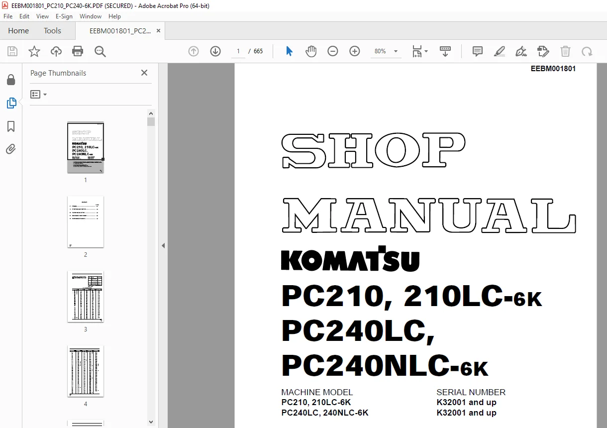
Komatsu PC210-6K, 210LC-6K PC240LC-6K,PC240NLC-6K Excavator Shop Manual PDF
$31.95
Komatsu PC210-6K, 210LC-6K PC240LC-6K,PC240NLC-6K Excavator Shop Manual EEBM001801 – PDF DOWNLOAD
- MACHINE MODEL SERIAL NUMBERPC210, 210LC-6K K32001 and upPC240LC, 240NLC-6K K32001 and up
Description
Komatsu PC210-6K, 210LC-6K PC240LC-6K,PC240NLC-6K Excavator Shop Manual EEBM001801 – PDF DOWNLOAD
FILE DETAILS:
Komatsu PC210-6K, 210LC-6K PC240LC-6K,PC240NLC-6K Excavator Shop Manual EEBM001801 – PDF DOWNLOAD
Language : English
Pages : 665
Downloadable : Yes
File Type : PDF
IMAGES PREVIEW OF THE MANUAL:
TABLE OF CONTENTS:
Komatsu PC210-6K, 210LC-6K PC240LC-6K,PC240NLC-6K Excavator Shop Manual EEBM001801 – PDF DOWNLOAD
- MACHINE MODEL SERIAL NUMBERPC210, 210LC-6K K32001 and upPC240LC, 240NLC-6K K32001 and up
10 STRUCTURE AND FUNCTION 24
ENGINE RELATED PARTS . 29
RADIATOR OIL COOLER 30
POWER TRAIN 31
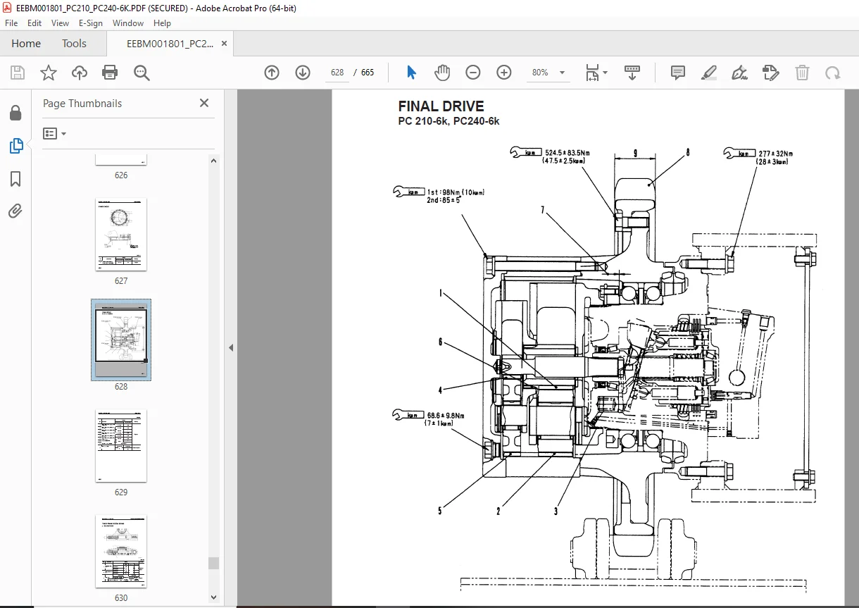
FINAL DRIVE 32
SWING CIRCLE . 33
SWING MACHINERY 34
TRACK FRAME, RECOIL SPRING . 35
TRACK SHOE . 36
HYDRAULIC TANK . 38
HYDRAULIC TANK . 39
HYDRAULIC PUMP . 40
CONTROL VALVE 59
SAFETY- SUCTION VALVE FOR SERVICE VALVE 67
SELF- REDUCING PRESSURE VALVE 68
CLSS . 73
SWING MOTOR 115
CENTER SWIVEL JOINT TRAVEL MOTOR .119
VALVE CONTROL WORK EQUIPMENT SWING PPC VALVE .129
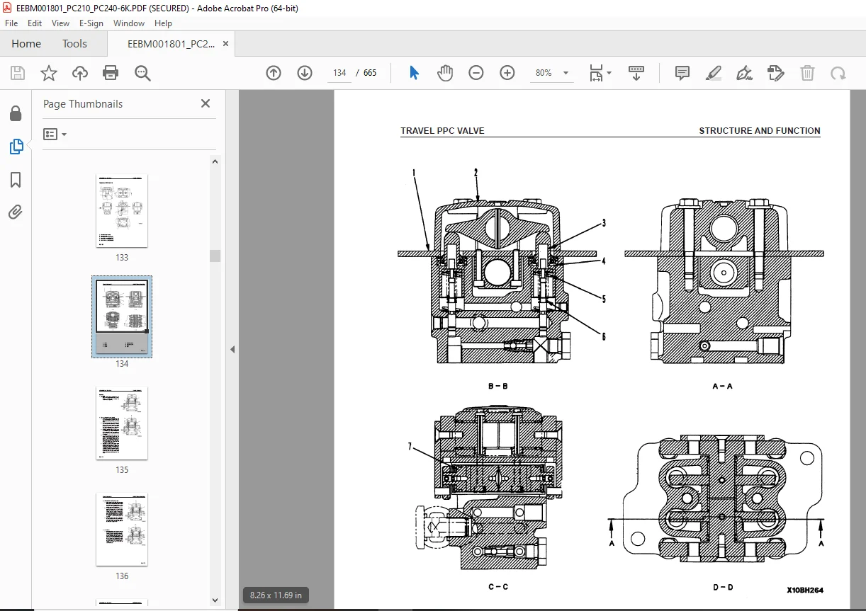
TRAVEL PPC VALVE .133
SERVICE PPC VALVE 137
SAFETY LOCK VALVE PPC ACCUMULATOR STRAIGHT- TRAVEL SYSTEM 142
EPC SOLENOID VALVE .143
OVERLOAD WARNING DEVICE 145
HOSE BURST PROTECTION VALVE (BOOM) .147
WORK EQUIPMENT ENGINE CONTROL SYSTEM .156
ELECTRONIC CONTROL SYSTEM 162
MACHINE MONITOR SYSTEM .187
20 TESTING AND ADJUSTING .201
TESTING AND ADJUSTING STANDARD VALUE TABLE .207
For engine – PC210- 6k .207
For engine – PC240- 6k For chassis .209
STANDARD VALUE TABLE FOR ELECTRICAL PARTS 218
MEASURING ENGINE SPEED .227
MEASURING EXHAUST GAS COLOR 228
ADJUSTING VALVE CLEARANCE 229
MEASURING COMPRESSION PRESSURE .230
MEASURING BLOW- BY PRES-SURE .230
TESTING AND ADJUSTING FUEL INJECTION TIMING 231
MEASURE ENGINE OIL PRESSURE 232
TESTING AND ADJUSTING FAN BELT TENSION .233
MEASURING SPEED SENSOR .234
TESTING AND ADJUSTING GOV-ERNOR MOTOR LEVER STROKE .235
TESTING AND ADJUSTING HYDRAULIC PRESSURE IN WORK EQUIPMENT, SWING AND TRAVEL CIRCUIT .236
TESTING AND ADJUSTING PC VALVE OUTPUT PRESSURE (SERVO PISTON INPUT PRES-SURE) 239
TESTING AND ADJUSTING LS VALVE OUTPUT PRESSURE (SERVO PISTON INPUT PRESSURE AND LS DIFFERENTIAL PRESSURE) 240
TESTING AND ADJUSTING CONTROL CIRCUIT OIL PRESSURE .243
TESTING SOLENOID VALVE OUT-PUT PRESSURE 244
MEASURING PPC VALVE OUTPUT PRESSURE 246
Pressure switch piping diagram .247
ADJUSTING WORK EQUIPMENT SWING PPC VALVE .248
ADJUSTMENT OF FLOW CON-TROL SYSTEM .249
Graph of PPC Pressure Against HCU Circuit Oil Flow .251
TESTING TRAVEL DEVIATION .252
TESTING LOCATIONS CAUSING HYDRAULIC DRIFT OF WORK EQUIPMENT 253
MEASURE OIL LEAKAGE 255
RELEASING REMAINING PRESSURE IN HYDRAULIC CIRCUIT 257
TESTING CLEARANCE OF SWING CIRCLE BEARING 257
TESTING AND ADJUSTING TRACK SHOE TENSION .258
BLEEDING AIR .259
SEQUENCE OF EVENTS IN TROUBLESHOOTING 261
POINTS TO REMEMBER WHEN CARRYING OUT MAINTENANCE .262
CHECKS BEFORE TROUBLESHOOTING 270
CONNECTOR TYPES AND MOUNTING LOCATIONS .272
CONNECTION TABLE FOR CONNECTOR PIN NUMBERS .277
EXPLANATION OF CONTROL MECHANISM FOR ELECTRICAL SYSTEM .285
DISPLAY METHOD AND SPECIAL FUNCTIONS OF MONITOR PANEL 286
METHOD OF USING JUDGEMENT TABLE 295
METHOD OF USING TROUBLESHOOTING CHARTS .297
DETAILS OF TROUBLESHOOTING AND TROUBLESHOOTING PROCEDURE .299
SERVICE CODE TABLE .304
TROUBLESHOOTING OF COMMUNICATION ABNORMALITY SYSTEM (N MODE) .305
TROUBLESHOOTING OF ENGINE THROTTLE PUMP CONTROLLER (GOVERNOR CONTROL SYSTEM) (E MODE) 307
ACTION TAKEN BY CONTROLLER WHEN ABNORMALITY OCCURS AND PROBLEMS ON MACHINE .308
JUDGEMENT TABLE FOR ENGINE THROTTLE PUMP GOVERNOR (GOVERNOR CONTROL SYSTEM) AND ENGINE RELATED PARTS .312
ELECTRICAL CIRCUIT DIAGRAM FOR E MODE SYSTEM .314
E- 1 Abnormality in engine throttle pump controller power source (controller LED is OFF) .316
E- 2 [E308] Abnormality in fuel control dial input value is displayed 317
E- 3 [E317] Abnormality (disconnection) in motor drive system is displayed .318
E- 4 [E318] Abnormality (short circuit) in motor drive system is displayed .319
E- 5 [E306] Abnormality in feedback potentiometer system is displayed 320
E- 6 [E315] Abnormality (short circuit) in battery relay output system is displayed 321
E- 7 [E316] Abnormality (step- out) in motor is displayed 322
E- 8 Engine does not start .324
E- 8 Related electric circuit diagram E- 9 Engine speed is irregular .327
E- 10 Lack of output (engine high idling speed is too low) .331
E- 11 Engine does not stop .333
E- 12 Defective operation of battery relay system (engine does not stop) .335
TROUBLESHOOTING OF ENGINE SYSTEM (S MODE) 337
S- 1 Starting performance is poor (starting always takes time) .342
S- 2 Engine does not start .344
S- 3 Engine does not pick up smoothly (follow- up is poor) .347
S- 4 Engine stops during operations 348
S- 5 Engine does not rotate smoothly (hunting) .349
S- 6 Engine lacks output (no power) 350
S- 7 Exhaust smoke is black (incomplete combustion) 351
S- 8 Oil consumption is excessive (or exhaust smoke is blue) .352
S- 9 Oil becomes contaminated quickly 353
S- 10 Fuel consumption is excessive 354
S- 11 Oil is in coolant, or coolant spurts black, or coolant level goes down .355
S- 12 Oil pressure caution lamp lights up (drop in oil pressure) .356
S- 13 Oil level rises (coolant, fuel in oil) .357
S- 14 Coolant temperature becomes too high (overheating) .358
S- 15 Abnormal noise is made .359
S- 16 Vibration is excessive .360
TROUBLESHOOTING OF ENGINE THROTTLE PUMP CONTROLLER (PUMP CONTROL SYSTEM) (C- MODE) .361
POINTS TO REMEMBER WHEN TROUBLESHOOTING PUMP CONTROLLER SYSTEM .361
ACTION TAKEN BY CONTROLLER WHEN ABNORMALITY OCCURS AND PROBLEMS ON MACHINE .362
JUDGEMENT TABLE FOR ENGINE THROTTLE PUMP CONTROLLER (PUMP CONTROL SYSTEM) AND HYDRAULIC RELATED PARTS ELECTICAL CIRCUIT DIAGRAM FOR C MODE AND F MODE 372
C- 1 Abnormality in controller power source system (controller LED is OFF) .374
C- 2 [E232] Short circuit in pump EPC solenoid system is displayed .375
C- 3 [E233] Disconnection in PC- EPC solenoid system is displayed 377
C- 4 [213] Disconnection in swing holding brake solenoid system is displayed .379
C- 5 [E203] Short circuit in swing holding brake solenoid system is displayed 381
C- 6 [E204] Short circuit in pump merge/ divider solenoid system is displayed 383
C- 7 [E214] Disconnection in pum merge/ divider solenoid system is displayed .384
C- 8 [E207] Short circuit in active mode solenoid system is displayed 385
C- 9 [E208] Disconnection in active mode solenoid system is displayed 386
C- 10 [E206] Short circuit in travel speed solenoid system is displayed 387
C- 13 [E215] Disconnection in 2- stage relief solenoid system is displayed .388
C- 14 [E217] Model selection input error is displayed 389
C- 15 [E222] Short circuit in LS- EPC solenoid system is displayed .391
C- 16 [E223] Disconnection in LS- EPC solenoid system is displayed .392
C- 17 [E224] Abnormality in front pump pressure sensor system is displayed .393
C- 18 [E225] Abnormality in rear pump pressure sensor system is displayed 394
C- 19 [E226] Abnormality in pressure sensor power source system is displayed .395
C- 20 [E227] Abnormality in engine speed sensor system is displayed 396
TROUBLESHOOTING OF ENGINE THROTTLE PUMP CONTROLLER (INPUT SIGNAL SYSTEM) (F MODE) 397
F- 1 Bit pattern 20 – (1) Swing oil pressure switch does not light up 397
F- 2 Bit pattern 20-( 2) Travel oil pressure switch does not light up 398
F- 3 Bit pattern 20-( 3) Boom LOWER oil pressure switch does not light up 400
F- 4 Bit pattern 20-( 4) Boom RAISE oil pressure switch does not light up 401
F- 5 Bit pattern 20-( 5) Arm IN oil pressure switch does not light up 402
F- 6 Bit pattern 20-( 6) Arm OUT oil pressure switch does not light up .403
F- 7 Bit pattern 21-( 1) Bucket CURL oil pressure switch does not light up .404
F- 8 Bit pattern 21-( 2) Bucket DUMP oil pressure switch does not light up .405
F- 9 Bit pattern 21-( 3) Swing lock switch does not light up .406
F- 10 Bit pattern 22-( 5) Kerosene mode connection does not light up .407
F- 11 Bit pattern 22-( 6) L. H. knob switch does not light up 408
TROUBLESHOOTING OF HYDRAULIC AND MECHANICAL SYSTEM (H- MODE) .409
PUMP MERGE/ DIVIDER LOGIC 413
SOLENOID ACTUATION TABLE .414
H- 1 Speeds of all work equipment, swing, travel are slow 415
H- 3 No work equipment, travel, swing move H- 2 There is excessive drop in engine speed, or engine stalls 417
H- 4 Abnormal noise generated (around pump) 418
H- 5 Auto- deceleration does not work (when PPC shuttle valve) .418
H- 6 Fine control ability is poor or response is poor 419
H- 7 Boom is slow or lacks power .421
H- 8 Arm is slow or lacks power 423
H- 9 Bucket is slow or lacks power .425
H- 10 Work equipment (boom, arm, bucket) does not move (but travel and swing are normal) .426
H- 11 Excessive hydraulic drift (boom, arm, bucket) 426
H- 12 Excessive time lag (engine at low idling) 427
H- 13 Other equipment moves when single circuit is relieved 427
M- 30 Related electric circuit diagram H- 14 Lack of power when pressure rises .430
H- 16 In compound operations, work equipment with larger load is slow 431
H- 15 In L/ O, F/ O modes, work equipment speed is faster than specified speed .431
H- 17 In swing + boom RAISE, boom RAISE is slow 432
H- 18 In swing + travel, travel speed drops excessively 432
H- 19 Travel deviation .432
H- 20 Travel speed is slow .433
H- 21 Steering does not turn easily or lacks power .435
H- 23 Travel does not move (one side only) .437
H- 22 Travel speed does not switch or is faster than specified speed .437
H- 24 Does not swing .438
H- 25 Swing acceleration is poor or swing speed is slow 439
H- 26 Excessive overrun when stopping swing 441
H- 27 Excessive shock when stopping wing (one direction only) H- 28 Excessive abnormal noise when stopping swing .442
H- 29 Excessive hydraulic drift of swing .442
H- 30 Swing speed is faster than specified speed in L/ O and F/ O modes 443
TROUBLESHOOTING OF MACHINE MONITOR SYSTEM (M CODE ) 444
ACTION TAKEN BY MONITOR PANEL WHEN ABNORMALITY OCCURS AND PROBLEMS ON MACHINE 444
ELECTRICAL CIRCUIT DIAGRAM FOR M MODE SYSTEM M- 1 [E101] Abnormality in error data is displayed [E102] Error in clock data is displayed 448
M- 2 [E103] Short circuit in buzzer output or contact of 24V wiring harness with buzzer drive harness is displayed .449
M- 3 [E104] Air clogging detected is displayed .450
M- 4 [E108] Engine coolant temperature 105° C detected is displayed 450
M- 5 When starting switch is turned ON, none of the lamps on the monitor panel light up for 3 seconds 451
M- 6 When starting switch is turned ON, monitor panel lamps all stay lit up and do not go out M- 7 When starting switch is turned ON, items lit up on monitor panel are different from actual machine (model) 453
M- 8 When starting switch is turned ON (engine stopped), basic check items flashes .454
M- 9 Preheating is not being used but (preheating monitor) lights up .457
M- 10 When starting switch is turned ON and engine is started, basic check items flash .458
M- 11 When starting switch is turned ON (engine stopped), caution items, emergency items flash (battery, engine oil pressure lamps do not light up) 460
M- 12 When starting switch is turned ON and engine is started, caution items, emergency items flash (then there is no abnormality in engine or items to check before troubleshooting) 462
M- 13 When starting switch is turned ON (engine stopped), buzzer does not sound for 1 second Caution item flashes but buzzer does not sound 465
M- 14 No abnormality is displayed on monitor but buzzer sounds .465
M- 15 Night lighting on monitor panel does not light up (liquid crystal display is normal) .466
M- 16 Coolant temperature gauge does not rise 467
M- 17 Coolant temperature gauge does not give any display (none of the gauge lamps light up during operation) 468
M- 18 Fuel level gauge always displays FULL 469
M- 19 Fuel level gauge does not give display .469
M- 20 Swing lock switch is turned ON (LOCK) but (swing lock monitor) does not light up .470
M- 21 Swing prolix switch is turned ON (prolix), but (swing lock monitor) does not flash .471
M- 22 Service meter does not advance while engine is running M- 23 When starting switch is at OFF and time switch is pressed, time and service meter are not displayed .472
M- 24 Defective fuel level sensor system .473
M- 25 Defective coolant temperature sensor system 474
M- 26 Defective engine oil sensor system .475
M- 27 Defective coolant level sensor system 476
M- 28 Defective hydraulic oil level sensor system 477
M- 29 Wiper does not work or switch is not being used but wiper is actuated 478
M- 30 Washer motor does not work, or switch is not being used but washer motor is actuated .483
30 DISASSEMBLY AND ASSEMBLY 485
METHOD OF USING MANUAL .490
SPECIAL TOOL LIST 493
SKETCHES OF SPECIAL TOOLS 497
STARTING MOTOR .498
ALTERNATOR .499
FUEL INJECTION PUMP 500
WATER PUMP .503
NOZZLE HOLDER 505
TURBOCHARGER .506
THERMOSTAT .507
GOVERNOR MOTOR .509
CYLINDER HEAD ASSEMBLY .510
RADIATOR HYDRAULIC OIL COOLER 518
ENGINE, MAIN PUMP 520
DAMPER .524
FUEL TANK 525
CENTER SWIVEL JOINT 526
FINAL DRIVE 529
SPROCKET .538
SWING MOTOR 539
SWING MACHINERY 540
SWING MACHINERY 541
REVOLVING FRAME 548
REMOVAL OF SWING CIRCLE ASSEMBLY .550
INSTALLATION OF SWING CIRCLE ASSEMBLY 551
REMOVAL OF IDLER RECOIL SPRING ASSEMBLY 552
INSTALLATION OF IDLER RECOIL SPRING ASSEMBLY .552
DISASSEMBLY OF RECOIL SPRING ASSEMBLY 553
ASSEMBLY OF RECOIL SPRING ASSEMBLY .554
DISASSEMBLY OF IDLER ASSEMBLY 555
ASSEMBLY OF IDLER ASSEMBLY .556
REMOVAL OF TRACK ROLLER ASSEMBLY .558
INSTALLATION OF TRACK ROLLER ASSEMBLY 558
DISASSEMBLY OF TRACK ROLLER ASSEMBLY .559
ASSEMBLY OF TRACK ROLLER ASSEMBLY 560
REMOVAL OF CARRIER ROLLER ASSEMBLY .562
INSTALLATION OF CARRIER ROLLER ASSEMBLY 562
DISASSEMBLY OF CARRIER ROLLER ASSEMBLY .563
ASSEMBLY OF CARRIER ROLLER ASSEMBLY 564
REMOVAL OF TRACK SHOE ASSEMBLY .566
INSTALLATION OF TRACK SHOE ASSEMBLY 566
HYDRAULIC TANK .567
MAIN PUMP 569
MAIN PUMP INPUT SHAFT OIL SEAL .572
CONTROL VALVE 573
PUMP MERGE- DIVIDER VALVE 582
MAIN RELIEF VALVE 583
PC VALVE .584
LS VALVE .585
PC, LS- EPC VALVE 586
SOLENOID VALVE .587
REMOVAL OF WORK EQUIPMENT SWING PPC VALVE ASSEMBLY .588
INSTALLATION OF WORK EQUIPMENT SWING PPC VALVE ASSEMBLY 588
TRAVEL PPC VALVE .591
REMOVAL OF BOOM CYLINDER ASSEMBLY 593
INSTALLATION OF BOOM CYLINDER ASSEMBLY .594
REMOVAL OF ARM CYLINDER ASSEMBLY .595
INSTALLATION OF ARM CYLINDER ASSEMBLY 596
REMOVAL OF BUCKET CYLINDER ASSEMBLY 597
INSTALLATION OF BUCKET CYLINDER ASSEMBLY .598
DISASSEMBLY OF HYDRAULIC CYLINDER ASSEMBLY .599
ASSEMBLY OF HYDRAULIC CYLINDER ASSEMBLY 601
WORK EQUIPMENT .604
BUCKET .606
ARM 608
BUCKET – ARM .610
BOOM .612
REMOVAL OF OPERATOR™S CAB ASSEMBLY .614
INSTALLATION OF OPERATOR™S CAB ASSEMBLY 616
COUNTERWEIGHT 617
REMOVAL OF ENGINE THROTTLE CONTROLLER ASSEMBLY .618
MONITOR 619
40 MAINTENANCE STANDARD 622
SWING MACHINERY 625
SWING CIRCLE FINAL DRIVE .628
TRACK FRAME, RECOIL SPRING .630
IDLER 631
CARRIER ROLLER .633
TRACK ROLLER .634
TRACK SHOE .635
HYDRAULIC PUMP .637
CONTROL VALVE 638
VARIABLE PRESSURE COMPENSATION VALVE .644
SAFETY- SUCTION VALVE FOR SERVICE VALVE 645
SELF- REDUCING PRESSURE VALVE 646
SWING MOTOR 647
TRAVEL MOTOR .648
TRAVEL PPC VALVE WORK EQUIPMENT SWING PPC VALVE EPC SOLENOID VALVE .651
CENTER SWIVEL JOINT HYDRAULIC CYLINDER .653
WORK EQUIPMENT DIMENSIONS OF WORK EQUIPMENT 661
DESCRIPTION:
Komatsu PC210-6K, 210LC-6K PC240LC-6K,PC240NLC-6K Excavator Shop Manual EEBM001801 – PDF DOWNLOAD
- MACHINE MODEL SERIAL NUMBERPC210, 210LC-6K K32001 and upPC240LC, 240NLC-6K K32001 and up
G.B 22/ 12/24



