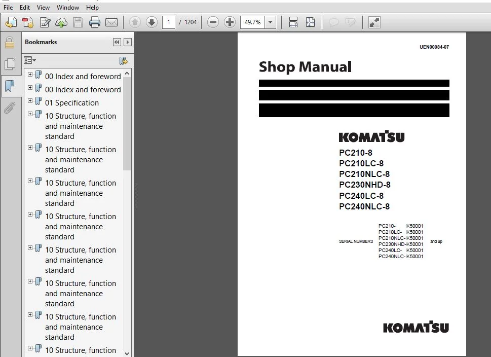
Komatsu PC210-8, PC210NLC-8, PC230NHD-8, PC240LC-8, PC240NLC-8 Excavator Shop Manual UEN00084-07
Original price was: $48.95.$34.95Current price is: $34.95.
SERIAL NUMBERS:
PC210- K50001 and up
PC210LC- K50001 and up
PC210NLC- K50001 and up
PC230NHD-K50001 and up
PC240LC- K50001 and up
PC240NLC- K50001 and up
Description
Komatsu PC210-8, PC210NLC-8, PC230NHD-8, PC240LC-8, PC240NLC-8 Excavator Shop Manual
FILE DETAILS:
Komatsu PC210-8, PC210NLC-8, PC230NHD-8, PC240LC-8, PC240NLC-8 Excavator Shop Manual
Brands: Komatsu
Equipment Type: Hydraulic Excavator
Manuals Type: Shop Manual
Machine Model: PC210-8, PC210LC-8, PC210NLC-8, PC230NHD-8, PC240LC-8, PC240NLC-8
Serial Number: K50001 and up
Book Code: UEN00084-07
Language: English
Pages: 1204
File Format: Portable Document Format (PDF)
DESCRIPTION:
Komatsu PC210-8, PC210NLC-8, PC230NHD-8, PC240LC-8, PC240NLC-8 Excavator Shop Manual
How to read the shop manual:
1. Composition of shop manual:
This shop manual contains the necessary technical information for services performed in a workshop. For ease of understanding, the manual is divided into the following sections.
00. Index and foreword:
This section contains the index, foreword, safety and basic information. If any revision is made, the LIST OF REVISED PAGES will be added.
01. Specification:
This section explains the specifications of the machine.
10. Structure and function:
This section explains the structure and function of each component. It serves not only to give an understanding for the structure of each component, but also serves as reference material for troubleshooting.
20. Standard value table:
This section explains the standard values for new machine and judgement criteria for testing, adjusting, and troubleshooting. This standard value table is used to check the standard values in testing and adjusting and to judge parts in troubleshooting.
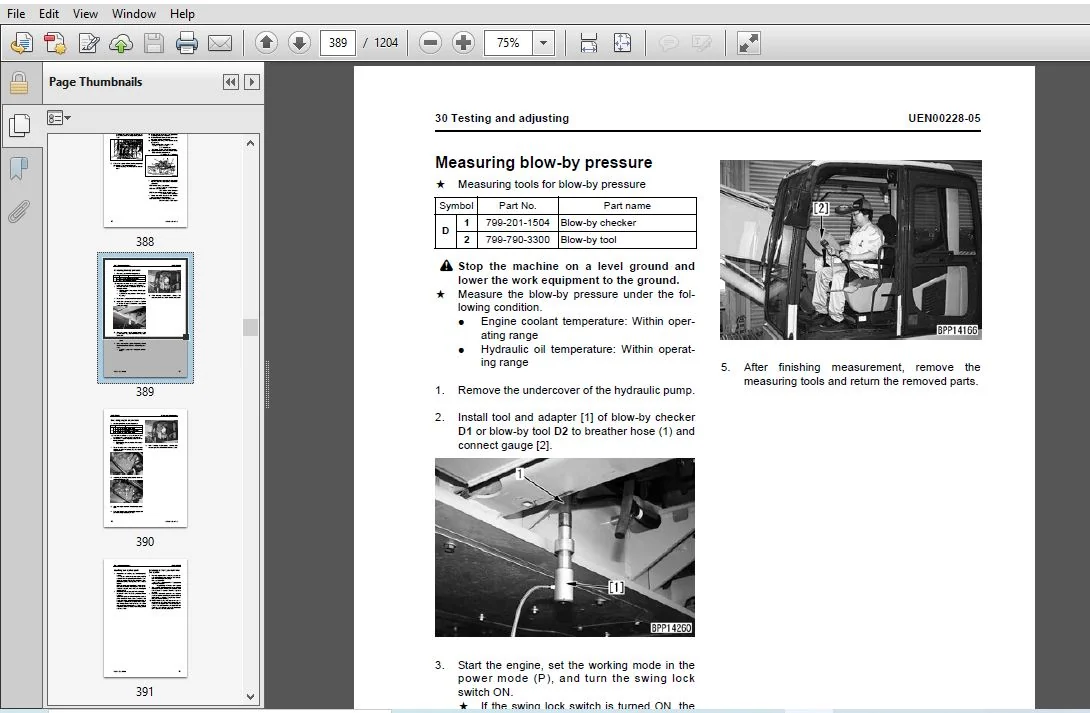
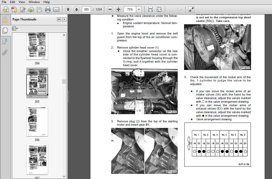
30. Testing and adjusting:
This section explains measuring tools and measuring methods for testing and adjusting, as well as the adjusting method of each part. The standard values and judgment criteria for “Testing and adjusting” are explained in “Standard value table”.
40. Troubleshooting:
This section explains how to find out failed parts and how to repair them. The troubleshooting is divided by failure modes. The “S mode” of the troubleshooting related to the engine may be also explained in the Chassis volume and Engine volume. In this case, see the Chassis volume.
50. Disassembly and assembly:
This section explains the special tools and procedures for removing, installing, disassembling, and assembling each component, as well as precautions for them. In addition, tightening torque, and quantity and weight of coating material, oil, grease, and coolant necessary for the work are also explained.
60. Maintenance standard:
This section gives maintenance standard values of each component. The maintenance standard sub-section explains the criteria and remedies for disassembly and service.
80. Appendix:
This section explains the structure, function, testing, adjusting, and troubleshooting for the equipment not classifiable in other sections.
90. Diagrams and drawings (chassis volume) /Repair and replacement of parts (engine volume):
- Chassis volume
This section gives hydraulic circuit diagrams and electrical circuit diagrams. - Engine volume
This section explains the method of remanufacturing and repairing engine and replacing parts.
TABLE OF CONTENTS:
Komatsu PC210-8, PC210NLC-8, PC230NHD-8, PC240LC-8, PC240NLC-8 Excavator Shop Manual
00 Index and foreword...........................................................................................................................................   3
	Index.......................................................................................................................................................   3
		Organization list of the shop manual....................................................................................................................   4
		Table of contents.......................................................................................................................................   6
00 Index and foreword...........................................................................................................................................  17
	Foreword and general information............................................................................................................................  17
		Foreword and general information........................................................................................................................  18
			Safety notice.......................................................................................................................................  18
			How to read the shop manual.........................................................................................................................  22
			Explanation of terms for maintenance standard.......................................................................................................  24
			Handling electric equipment and hydraulic component.................................................................................................  26
			How to read electric wire code......................................................................................................................  34
			Method of disassembling and connecting push-pull type coupler.......................................................................................  37
			Standard tightening torque table....................................................................................................................  40
			Conversion table....................................................................................................................................  44
01 Specification................................................................................................................................................  51
	Specification and technical data............................................................................................................................  51
		Specification and technical data........................................................................................................................  52
			Specification dimension drawings....................................................................................................................  52
			Working range diagram...............................................................................................................................  53
			Specifications......................................................................................................................................  54
			Weight table........................................................................................................................................  58
			Table of fuel, coolant and lubricants...............................................................................................................  62
10 Structure, function and maintenance standard.................................................................................................................  65
	Engine and cooling system...................................................................................................................................  65
		Engine and cooling system...............................................................................................................................  66
			Engine related parts................................................................................................................................  66
			Radiator, oil cooler, aftercooler and fuel cooler...................................................................................................  67
		Diesel Particulate Filter...............................................................................................................................  68
			Diesel Particulate Filter - Component Parts.........................................................................................................  69
			System Description..................................................................................................................................  70
			Regeneration........................................................................................................................................  70
10 Structure, function and maintenance standard.................................................................................................................  73
	Power train.................................................................................................................................................  73
		Power train.............................................................................................................................................  74
			Power train.........................................................................................................................................  74
			Final drive.........................................................................................................................................  76
			Swing machinery.....................................................................................................................................  78
			Swing circle........................................................................................................................................  82
10 Structure, function and maintenance standard.................................................................................................................  85
	Undercarriage and frame.....................................................................................................................................  85
		Undercarriage and frame.................................................................................................................................  86
			Track frame and recoil spring.......................................................................................................................  86
			Idler...............................................................................................................................................  88
			Carrier roller......................................................................................................................................  90
			Track roller........................................................................................................................................  91
			Track shoe..........................................................................................................................................  92
10 Structure, function and maintenance standard.................................................................................................................  99
	Hydraulic system, Part 1....................................................................................................................................  99
		Hydraulic system, Part 1................................................................................................................................ 100
			Hydraulic equipment layout drawing.................................................................................................................. 100
		Hydraulic tank and filter............................................................................................................................... 102
			Hydraulic pump...................................................................................................................................... 103
			Hydraulic pump...................................................................................................................................... 104
			Pilot oil filter.................................................................................................................................... 127
10 Structure, function and maintenance standard................................................................................................................. 129
	Hydraulic system, Part 2.................................................................................................................................... 129
		Hydraulic system, Part 2................................................................................................................................ 130
			Control valve....................................................................................................................................... 130
			CLSS................................................................................................................................................ 143
			Functions and operation by valve.................................................................................................................... 148
			Hydraulic drift prevention valve.................................................................................................................... 174
10 Structure, function and maintenance standard................................................................................................................. 187
	Hydraulic system, Part 3.................................................................................................................................... 187
		Hydraulic system, Part 3................................................................................................................................ 189
			Swing motor......................................................................................................................................... 189
			Centre swivel joint................................................................................................................................. 198
			Travel motor........................................................................................................................................ 201
			PPC valve........................................................................................................................................... 212
			Valve control....................................................................................................................................... 232
			ATT EPC Valve Assembly.............................................................................................................................. 234
			Solenoid valve...................................................................................................................................... 236
			PPC Accumulator..................................................................................................................................... 238
			Return oil filter................................................................................................................................... 239
			Attachment circuit selector valve................................................................................................................... 240
			Quick coupler control valve - For PC210 K50001 ~ K51094, PC230 K50001 ~ K50113 and PC240 K50001~K50303.............................................. 242
			Quick coupler control valve - For PC210 K51095 - K53243, PC230 K50114 - K50286 and PC240 K50304 - K51093.).......................................... 244
			Quick coupler control valve - For PC210 K53424 and up, PC230 K50287 and up and PC240 K51094 and up.................................................. 246
			Hydraulic cylinder.................................................................................................................................. 248
10 Structure, function and maintenance standard................................................................................................................. 253
	Work equipment.............................................................................................................................................. 253
		Work equipment.......................................................................................................................................... 254
			Dimensions of components............................................................................................................................ 254
10 Structure, function and maintenance standard................................................................................................................. 261
	Cab and its attachments..................................................................................................................................... 261
		Cab and its attachments................................................................................................................................. 262
			Air conditioner piping.............................................................................................................................. 262
10 Structure, function and maintenance standard................................................................................................................. 265
	Electrical system........................................................................................................................................... 265
		Electrical system....................................................................................................................................... 266
			Engine control...................................................................................................................................... 266
			Electrical control system........................................................................................................................... 274
			Monitor system...................................................................................................................................... 300
			Sensor.............................................................................................................................................. 331
			PPC Levers.......................................................................................................................................... 334
			KOMTRAX terminal system............................................................................................................................. 336
10 Structure, function and maintenance standard................................................................................................................. 339
	Auto Grease system.......................................................................................................................................... 339
		Outline of Auto Grease System........................................................................................................................... 340
20 Standard value table......................................................................................................................................... 355
	Standard service value table................................................................................................................................ 355
		Standard service value table............................................................................................................................ 356
			Standard value table for engine related parts....................................................................................................... 356
			Standard value table for chassis related parts...................................................................................................... 358
30 Testing and adjusting........................................................................................................................................ 377
	Testing and adjusting, Part 1............................................................................................................................... 377
		Testing and adjusting, Part 1........................................................................................................................... 379
			Tools for testing, adjusting, and troubleshooting................................................................................................... 379
			Measuring engine speed.............................................................................................................................. 382
			Measuring intake air pressure (boost pressure)...................................................................................................... 383
			Checking exhaust gas colour......................................................................................................................... 384
			Adjusting valve clearance........................................................................................................................... 385
			Measuring compression pressure...................................................................................................................... 387
			Measuring blow-by pressure.......................................................................................................................... 389
			Measuring engine oil pressure....................................................................................................................... 390
			Handling fuel system parts.......................................................................................................................... 391
			Releasing residual pressure from fuel system........................................................................................................ 391
			Measuring fuel pressure............................................................................................................................. 392
			Measuring fuel return rate and leakage.............................................................................................................. 394
			Bleeding air from fuel circuit...................................................................................................................... 396
			Checking fuel circuit for leakage................................................................................................................... 398
			Checking and adjusting air conditioner compressor belt tension...................................................................................... 399
			Measuring swing circle bearing clearance............................................................................................................ 400
			Checking and adjusting track shoe tension........................................................................................................... 401
			Measuring and adjusting oil pressure in work equipment, swing, and travel circuits.................................................................. 403
			Measuring control circuit basic pressure............................................................................................................ 407
			Measuring and adjusting oil pressure in pump PC control circuit..................................................................................... 408
			Measuring and adjusting oil pressure in pump LS control circuit..................................................................................... 412
			Measuring solenoid valve output pressure............................................................................................................ 418
			Measuring PPC valve output pressure................................................................................................................. 421
			Adjusting play of work equipment and swing PPC valves............................................................................................... 423
			Measuring and adjusting quick coupler control valve output pressure - For PC210 K50001 - K53423, PC230 K50001 - K50286 and PC240 K50001 - K51093.... 424
			Measuring and adjusting quick coupler control valve output pressure - For PC210 K53424 and up, PC230 K50287 and up and PC240 K51094 and up.......... 425
			Checking parts which cause hydraulic drift of work equipment........................................................................................ 426
			Releasing residual pressure from hydraulic circuit.................................................................................................. 428
			Measuring oil leakage............................................................................................................................... 429
			Bleeding air from each part......................................................................................................................... 432
			Checking cab tipping stopper........................................................................................................................ 435
			Adjusting mirrors................................................................................................................................... 436
			Adjusting mirrors................................................................................................................................... 438
30 Testing and adjusting........................................................................................................................................ 441
	Testing and adjusting, Part 2............................................................................................................................... 441
		Testing and adjusting, Part 2........................................................................................................................... 442
			Special functions of machine monitor................................................................................................................ 442
30 Testing and adjusting........................................................................................................................................ 507
	Testing and adjusting, Part 3............................................................................................................................... 507
		Testing and adjusting, Part 3........................................................................................................................... 508
			Handling high-voltage circuit of engine controller.................................................................................................. 508
			Preparation work for troubleshooting of electrical system........................................................................................... 509
			Procedure for testing diodes........................................................................................................................ 513
			Pm Clinic service................................................................................................................................... 515
			Warning............................................................................................................................................. 517
			Pm Clinic service................................................................................................................................... 521
40 Troubleshooting.............................................................................................................................................. 529
	General information on troubleshooting...................................................................................................................... 529
		General information on troubleshooting.................................................................................................................. 530
			Points to remember when troubleshooting............................................................................................................. 530
			Sequence of events in troubleshooting............................................................................................................... 531
			Check before troubleshooting........................................................................................................................ 532
			Classification and procedures for troubleshooting................................................................................................... 533
			How to read electric wire code...................................................................................................................... 537
			Connection table for connector pin numbers.......................................................................................................... 540
			T-boxes and T-adapters table........................................................................................................................ 571
40 Troubleshooting.............................................................................................................................................. 577
	Troubleshooting by failure code (Display of code), Part 1................................................................................................... 577
		Troubleshooting by failure code (Display of code), Part 1............................................................................................... 579
			Failure codes table................................................................................................................................. 579
			Before carrying out troubleshooting when failure code is displayed.................................................................................. 584
			Before carrying out troubleshooting when failure code is displayed.................................................................................. 585
			Information in troubleshooting table................................................................................................................ 590
			Failure code [989L00] Engine Controller Lock Caution 1.............................................................................................. 592
			Failure code [989M00] Engine Controller Lock Caution 2.............................................................................................. 592
			Failure code [989N00] Engine Controller Lock Caution 3.............................................................................................. 593
			Failure code [AA10NX] Air Cleaner Clogging.......................................................................................................... 593
			Failure code [AB00KE] Charge Voltage Low............................................................................................................ 594
			Failure code [B@BAZG] Eng Oil Press. Low............................................................................................................ 596
			Failure code [B@BAZK] Eng Oil Level Low............................................................................................................. 596
			Failure code [B@BCNS] Eng Water Overheat............................................................................................................ 597
			Failure code [B@BCZK] Eng Water Level Low........................................................................................................... 597
			Failure code [B@HANS] Hydr Oil Overheat............................................................................................................. 598
			Failure code [CA111] EMC Critical Internal Failure.................................................................................................. 598
			Failure code [CA115] Eng Ne and Bkup Speed Sens Error............................................................................................... 599
			Failure code [CA122] Chg Air Press Sensor High Error................................................................................................ 600
			Failure code [CA123] Chg Air Press Sensor Low Error................................................................................................. 602
			Failure code [CA131] Throttle Sensor High Error..................................................................................................... 604
			Failure code [CA132] Throttle Sensor Low Error...................................................................................................... 606
			Failure code [CA144] Coolant Temp Sens High Error................................................................................................... 608
			Failure code [CA145] Coolant Temp Sens Low Error.................................................................................................... 610
			Failure code [CA153] Chg Air Temp Sensor High Error................................................................................................. 612
			Failure code [CA154] Chg Air Temp Sensor Low Error.................................................................................................. 614
			Failure code [CA155] Chg Air Temp High Speed Derate................................................................................................. 616
			Failure code [CA187] Sens Supply 2 Volt Low Error................................................................................................... 618
			Failure code [CA221] Ambient Press Sens High Error.................................................................................................. 620
			Failure code [CA222] Ambient Press Sens Low Error................................................................................................... 622
			Failure code [CA227] Sens Supply 2 Volt High Error.................................................................................................. 624
			Failure code [CA234] Eng Overspeed.................................................................................................................. 625
			Failure code [CA238] Ne Speed Sens Supply Volt Error................................................................................................ 626
			Failure code [CA271] IMV/PCV1 Short Error........................................................................................................... 627
			Failure code [CA272] IMV/PCV1 Open Error............................................................................................................ 628
			Failure code [CA322] Inj #1 (L#1) Open/Short Error.................................................................................................. 630
			Failure code [CA323] Inj #5 (L#5) Open/Short Error.................................................................................................. 632
			Failure code [CA324] Inj #3 (L#3) Open/Short Error.................................................................................................. 634
			Failure code [CA325] Inj #6 (L#6) Open/Short Error.................................................................................................. 636
			Failure code [CA331] Inj #2 (L#2) Open/Short Error.................................................................................................. 638
			Failure code [CA332] Inj #4 (L#4) Open/Short Error.................................................................................................. 640
40 Troubleshooting.............................................................................................................................................. 643
	Troubleshooting by failure code (Display of code), Part 2................................................................................................... 643
		Troubleshooting by failure code (Display of code), Part 2............................................................................................... 645
			Failure code [CA342] Calibration Code Incompatibility............................................................................................... 645
			Failure code [CA351] Injectors Drive Circuit Error.................................................................................................. 646
			Failure code [CA352] Sens Supply 1 Volt Low Error................................................................................................... 648
			Failure code [CA386] Sens Supply 1 Volt High Error.................................................................................................. 650
			Failure code [CA428] Water in Fuel Sensor High Error................................................................................................ 652
			Failure code [CA429] Water in Fuel Sensor Low Error................................................................................................. 654
			Failure code [CA435] Eng Oil Press Sw Error......................................................................................................... 656
			Failure code [CA441] Battery Voltage Low Error...................................................................................................... 657
			Failure code [CA442] Battery Voltage High Error..................................................................................................... 660
			Failure code [CA449] Rail Press Very High Error..................................................................................................... 662
			Failure code [CA451] Rail Press Sensor High Error................................................................................................... 664
			Failure code [CA452] Rail Press Sensor Low Error.................................................................................................... 666
			Failure code [CA488] Chg Air Temp High Torque Derate................................................................................................ 668
			Failure code [CA553] Rail Press High Error.......................................................................................................... 668
			Failure code [CA559] Rail Press Low Error........................................................................................................... 669
			Failure code [CA689] Eng Ne Speed Sensor Error...................................................................................................... 670
			Failure code [CA731] Eng Bkup Speed Sens Phase Error................................................................................................ 672
			Failure code [CA757] All Continuous Data Lost Error................................................................................................. 674
			Failure code [CA778] Eng Bkup Speed Sensor Error.................................................................................................... 676
			Failure code [CA1633] KOMNET Datalink Timeout Error................................................................................................. 678
			Failure code [CA2185] Throt Sens Sup Volt High Error................................................................................................ 680
			Failure code [CA2186] Throt Sens Sup Volt Low Error................................................................................................. 681
			Failure code [CA2249] Rail Press Very Low Error..................................................................................................... 682
			Failure code [CA2311] IMV Solenoid Error............................................................................................................ 684
			Failure code [CA2555] Grid Htr Relay Volt High Error................................................................................................ 686
			Failure code [CA2556] Grid Htr Relay Volt Low Error................................................................................................. 688
			Failure code [D19JKZ] Personal Code Relay Abnormality............................................................................................... 690
			Failure code [D862KA] GPS Antenna Discon............................................................................................................ 692
			Failure code [DA25KP] 5V Sensor 1 Power Abnormality................................................................................................. 693
			Failure code [DA29KQ] Model Selection Abnormality................................................................................................... 700
40 Troubleshooting.............................................................................................................................................. 705
	Troubleshooting by failure code (Display of code), Part 3................................................................................................... 705
		Troubleshooting by failure code (Display of code), Part 3............................................................................................... 708
			Failure code [DA2RMC] CAN Discon (Pump Con Detected)................................................................................................ 708
			Failure code [DAFGMC] GPS Module Error.............................................................................................................. 710
			Failure code [DAFRMC] CAN Discon (Monitor Detected)................................................................................................. 712
			Failure code [DGH2KB] Hydr Oil Sensor Short......................................................................................................... 714
			Failure code [DHPAMA] F Pump Press Sensor Abnormality............................................................................................... 716
			Failure code [DHPBMA] R Pump Press Sensor Abnormality............................................................................................... 718
			Failure code [DHS3MA] Arm Curl PPC Press Sensor Abnormality......................................................................................... 720
			Failure code [DHS4MA] Bucket Curl PPC Press Sensor Abnormality...................................................................................... 722
			Failure code [DHS8MA] Boom Raise PPC Press Sensor Abnormality....................................................................................... 724
			Failure code [DHSAMA] Swing RH PPC Press Sensor Abnormality......................................................................................... 726
			Failure code [DHSBMA] Swing LH PPC Press Sensor Abnormality......................................................................................... 728
			Failure code [DHSDMA] Bucket Dump PPC Press Sensor Abnormality...................................................................................... 730
			Failure code [DHX1MA] Overload Sensor Abnormality (Analog).......................................................................................... 732
			Failure code [DW43KA] Travel Speed Sol Discon....................................................................................................... 734
			Failure code [DW43KB] Travel Speed Sol Short........................................................................................................ 736
			Failure code [DW45KA] Swing Brake Sol Discon........................................................................................................ 738
			Failure code [DW45KB] Swing Brake Sol Short......................................................................................................... 740
			Failure code [DW91KA] Travel Junction Sol Discon.................................................................................................... 742
			Failure code [DW91KB] Travel Junction Sol Short..................................................................................................... 744
			Failure code [DWA2KA] Service Sol Discon............................................................................................................ 746
			Failure code [DWA2KB] Service Sol Short............................................................................................................. 747
			Failure code [DWK0KA] 2-stage Relief Sol Discon..................................................................................................... 748
			Failure code [DWK0KB] 2-stage Relief Sol Short...................................................................................................... 750
40 Troubleshooting.............................................................................................................................................. 753
	Troubleshooting by failure code (Display of code), Part 4................................................................................................... 753
		Troubleshooting by failure code (Display of code), Part 4............................................................................................... 755
			Failure code [DXA8KA] PC-EPC (F) Sol Discon......................................................................................................... 755
			Failure code [DXA8KB] PC-EPC (F) Sol Short.......................................................................................................... 757
			Failure code [DXA9KA] PC-EPC (R) Sol Discon......................................................................................................... 759
			Failure code [DXA9KB] PC-EPC (R) Sol Short.......................................................................................................... 761
			Failure code [DXE0KA] LS-EPC Sol Discon............................................................................................................. 763
			Failure code [DXE0KB] LS-EPC Sol Short.............................................................................................................. 765
			Failure code [DXE4KA] Service Current EPC Discon.................................................................................................... 767
			Failure code [DXE4KB] Service Current EPC Short..................................................................................................... 769
			Failure code [DXE5KA] Merge-divider Main Sol Discon................................................................................................. 771
			Failure code [DXE5KB] Merge-divider Main Sol Short.................................................................................................. 773
			Failure code [DXE6KA] Merge-divider LS Sol Discon................................................................................................... 775
			Failure code [DXE6KB] Merge-divider LS Sol Short.................................................................................................... 777
			Failure code [DY20KA] Wiper Working Abnormality..................................................................................................... 779
			Failure code [DY20MA] Wiper Parking Abnormality..................................................................................................... 781
			Failure code [DY2CKA] Washer Drive Discon........................................................................................................... 783
			Failure code [DY2CKB] Washer Drive Short............................................................................................................ 785
			Failure code [DY2DKB] Wiper Drive (For) Short....................................................................................................... 787
			Failure code [DY2EKB] Wiper Drive (Rev) Short....................................................................................................... 789
			Failure code [DXEAKA] Service Current EPC1 Discon................................................................................................... 791
			Failure code [DXEAKB] Service Current EPC1 Short.................................................................................................... 792
			Failure code [DXE7KA] Service Current EPC2 Discon................................................................................................... 793
			Failure code [DXE7KB] Service Current EPC2 Short.................................................................................................... 794
			Failure code [DXE8KA] Service Current EPC3 Discon................................................................................................... 795
			Failure code [DXE8KB] Service Current EPC3 Short.................................................................................................... 796
			Failure code [DXE9KA] Service Current EPC4 Discon................................................................................................... 797
			Failure code [DXE9KB] Service Current EPC4 Short.................................................................................................... 798
			Failure code [DFB1KZ] Service Lever Potentio 1 Abnormality.......................................................................................... 801
			Failure code [DFB2KZ] Service Lever Potentio 2 Abnormality.......................................................................................... 803
			Failure code [DFB5KZ] Service Lever Sub Potentio 1 Abnormality...................................................................................... 805
			Failure code [DFB6KZ] Service Lever Sub Potentio 2 Abnormality...................................................................................... 807
			Failure code [DFB3L8] Service Lever 1 Potentio Error................................................................................................ 809
			Failure code [DFB4L8] Service Lever 2 Potentio Error................................................................................................ 810
40 Troubleshooting.............................................................................................................................................. 813
	Troubleshooting of electrical system (E-mode)............................................................................................................... 813
		Troubleshooting of electrical system (E-mode)........................................................................................................... 815
		Before carrying out troubleshooting of electrical system................................................................................................ 815
		Troubleshooting of electrical system (E-mode)........................................................................................................... 816
		Information in troubleshooting table.................................................................................................................... 819
		E-1 When starting switch turned ON, machine monitor displays nothing.................................................................................... 820
		E-2 When starting switch turned ON (before starting engine), basic check item lights up................................................................. 822
		E-3 Engine does not start (Engine does not turn)........................................................................................................ 825
		E-4 Preheater does not operate.......................................................................................................................... 828
		E-5 Automatic warm-up system does not operate (in cold season).......................................................................................... 830
		E-6 All work equipment, swing, and travel mechanism do not move or cannot be locked..................................................................... 832
		E-7 Precaution lights up while engine is running........................................................................................................ 834
		E-8 Emergency stop item lights up while engine is running............................................................................................... 839
		E-9 Engine coolant temperature gauge does not indicate normally......................................................................................... 840
		E-10 Hydraulic oil temperature gauge does not indicate normally......................................................................................... 841
		E-11 Fuel level gauge does not indicate normally........................................................................................................ 843
		E-12 Contents of display by machine monitor are different from applicable machine....................................................................... 845
		E-13 Machine monitor does not display some items........................................................................................................ 845
		E-14 Function switch does not work...................................................................................................................... 845
		E-15 Auto-decelerator does not operate normally......................................................................................................... 846
		E-16 Working mode does not change....................................................................................................................... 847
		E-17 Travel speed does not change....................................................................................................................... 848
		E-18 Alarm buzzer cannot be stopped..................................................................................................................... 849
		E-18 Alarm buzzer cannot be stopped..................................................................................................................... 850
		E-19 Windshield wiper and window washer do not operate.................................................................................................. 852
		E-20 Power maximising function does not operate normally................................................................................................ 854
		E-20 Power maximising function does not operate normally................................................................................................ 856
		E-21 Swing holding brake does not operate normally...................................................................................................... 858
		E-22 Travel alarm does not sound or does not stop sounding.............................................................................................. 860
		E-23 Air conditioner does not operate normally (including air conditioner abnormality record)........................................................... 862
		E-24 When starting switch is turned OFF, service meter is not displayed................................................................................. 874
		E-25 Machine monitor cannot be set in service mode...................................................................................................... 874
		E-26 Monitoring function does not display lever control signal normally................................................................................. 875
		E-27 KOMTRAX system does not operate normally........................................................................................................... 884
40 Troubleshooting.............................................................................................................................................. 887
	Troubleshooting of hydraulic and mechanical system (H-mode)................................................................................................. 887
		Troubleshooting of hydraulic and mechanical system (H-mode)............................................................................................. 890
			System diagram of hydraulic and mechanical system................................................................................................... 890
			Information in troubleshooting table................................................................................................................ 892
			H-1 Speed or power of whole work equipment, swing, and travel is low................................................................................ 893
			H-2 Engine speed lowers extremely or engine stalls.................................................................................................. 895
			H-3 Work equipment, swing, and travel systems do not work........................................................................................... 896
			H-4 Abnormal sound comes out from around hydraulic pump............................................................................................. 896
			H-5 Auto-decelerator does not operate............................................................................................................... 897
			H-6 Fine control performance or response is low..................................................................................................... 897
			H-7 Speed or power of boom is low................................................................................................................... 898
			H-8 Speed or power of arm is low.................................................................................................................... 899
			H-9 Speed or power of bucket is low................................................................................................................. 900
			H-10 Work equipment does not move singly............................................................................................................ 900
			H-11 Hydraulic drift of work equipment is large..................................................................................................... 901
			H-12 Time lag of work equipment is large............................................................................................................ 903
			H-13 When part of work equipment is relieved singly, other parts of work equipment move............................................................. 903
			H-14 Power maximizing function does not work........................................................................................................ 904
			H-15 In compound operation of work equipment, speed of part loaded more is low...................................................................... 904
			H-16 When machine swings and raises boom simultaneously, boom rising speed is low................................................................... 905
			H-17 When machine swings and travels simultaneously, travel speed lowers largely.................................................................... 905
			H-18 Machine deviates during travel................................................................................................................. 906
			H-19 Travel speed is low............................................................................................................................ 907
			H-20 Machine is not steered well or steering power is low........................................................................................... 908
			H-21 Travel speed does not change or travel speed is low/high....................................................................................... 909
			H-22 Travel system does not move (only one side).................................................................................................... 910
			H-23 Upper structure does not swing................................................................................................................. 911
			H-24 Swing acceleration or swing speed is low....................................................................................................... 913
			H-25 Upper structure overruns remarkably when it stops swinging..................................................................................... 914
			H-26 Large shock is made when upper structure stops swinging........................................................................................ 915
			H-27 Large sound is made when upper structure stops swinging........................................................................................ 915
			H-28 Hydraulic drift of swing is large.............................................................................................................. 916
			H-29 Attachment circuit is not changed.............................................................................................................. 917
			H-30 Oil flow in attachment circuit cannot be controlled............................................................................................ 917
			Quick coupler....................................................................................................................................... 918
			Quick coupler....................................................................................................................................... 920
			Quick coupler....................................................................................................................................... 922
40 Troubleshooting.............................................................................................................................................. 927
	Troubleshooting of engine (S-mode).......................................................................................................................... 927
		Troubleshooting of engine (S-mode)...................................................................................................................... 929
			Method of using troubleshooting chart............................................................................................................... 929
			S-1 Starting performance is poor.................................................................................................................... 932
			S-2 Engine does not start........................................................................................................................... 933
			S-3 Engine does not pick up smoothly................................................................................................................ 936
			S-4 Engine stops during operations.................................................................................................................. 937
			S-5 Engine does not rotate smoothly................................................................................................................. 938
			S-6 Engine lack output (or lacks power)............................................................................................................. 939
			S-7 Exhaust smoke is black (incomplete combustion).................................................................................................. 941
			S-8 Oil consumption is excessive (or exhaust smoke is blue)......................................................................................... 942
			S-9 Oil becomes contaminated quickly................................................................................................................ 943
			S-10 Fuel consumption is excessive.................................................................................................................. 944
			S-11 Oil is in coolant (or coolant spurts back or coolant level goes down).......................................................................... 945
			S-12 Oil pressure drops............................................................................................................................. 946
			S-13 Oil level rises (Entry of coolant/fuel)........................................................................................................ 947
			S-14 Coolant temperature becomes too high (overheating)............................................................................................. 948
			S-15 Abnormal noise is made......................................................................................................................... 949
			S-16 Vibration is excessive......................................................................................................................... 950
			S-17 Diesel Particulate Filter System............................................................................................................... 951
40 Troubleshooting.............................................................................................................................................. 953
	Troubleshooting of Auto Grease system....................................................................................................................... 953
50 Disassembly and assembly..................................................................................................................................... 961
	Disassembly and assembly related information................................................................................................................ 961
		Disassembly and assembly related information............................................................................................................ 962
			How to read this manual............................................................................................................................. 962
			List of adhesives................................................................................................................................... 964
			Special tool list................................................................................................................................... 967
			Sketches of special tools........................................................................................................................... 972
50 Disassembly and assembly..................................................................................................................................... 977
	Engine cooling related...................................................................................................................................... 977
		Engine cooling related.................................................................................................................................. 978
			Removal and installation of fuel supply pump assembly............................................................................................... 978
			Removal and installation of fuel injector assembly.................................................................................................. 980
			Removal and installation of engine front seal....................................................................................................... 987
			Removal and installation of engine rear seal........................................................................................................ 990
			Removal and installation of cylinder head assembly.................................................................................................. 993
			Removal and installation of radiator assembly.......................................................................................................1005
			Removal and installation of assembly hydraulic oil cooler assembly..................................................................................1008
			Removal and installation of aftercooler assembly....................................................................................................1010
			Removal and installation of fuel cooler assembly....................................................................................................1012
			Removal and installation of engine and hydraulic pump assemblies....................................................................................1013
50 Disassembly and assembly.....................................................................................................................................1025
	Power train.................................................................................................................................................1025
		Power train.............................................................................................................................................1026
			Removal and installation of final drive assembly....................................................................................................1026
			Disassembly and assembly of final drive assembly....................................................................................................1028
			Removal and installation of swing motor and swing machinery assembly................................................................................1044
			Disassembly and assembly of swing motor and swing machinery assembly................................................................................1046
			Removal and installation of swing circle assembly...................................................................................................1056
50 Disassembly and assembly.....................................................................................................................................1059
	Under carriage and frame....................................................................................................................................1059
		Under carriage and frame................................................................................................................................1060
			Disassembly and assembly of carrier roller..........................................................................................................1060
			Disassembly and assembly of track roller assembly...................................................................................................1063
			Disassembly and assembly of idler assembly..........................................................................................................1065
			Disassembly and assembly of recoil spring...........................................................................................................1068
			Removal and installation of sprocket................................................................................................................1070
			Expansion and installation of track shoe assembly...................................................................................................1071
			Removal and installation of revolving frame assembly................................................................................................1073
			Removal and installation of counterweight assembly..................................................................................................1075
50 Disassembly and assembly.....................................................................................................................................1077
	Hydraulic system............................................................................................................................................1077
		Hydraulic system........................................................................................................................................1078
			Removal and installation of center swivel joint assembly............................................................................................1078
			Disassembly and assembly of center swivel joint assembly............................................................................................1080
			Removal and installation of hydraulic tank assembly.................................................................................................1081
			Removal and installation of control valve assembly..................................................................................................1084
			Disassembly and assembly of control valve assembly..................................................................................................1089
			Removal and installation of hydraulic pump assembly.................................................................................................1093
			Removal and installation of oil seal in hydraulic pump input shaft..................................................................................1098
			Disassembly and assembly of work equipment PPC valve assembly.......................................................................................1099
			Disassembly and assembly of travel PPC valve assembly...............................................................................................1100
			Disassembly and assembly of hydraulic cylinder assembly.............................................................................................1101
			Disassembly and Assembly of Quick Coupler Valve - For PC210 K50001 - K53423, PC230 K50001 - K50286 and PC240 K50001 - K51093........................1107
			Disassembly and Assembly of Quick Coupler Valve - For PC210 K53424 and up, PC230 K50287 and up and PC240 K51094 and up..............................1108
50 Disassembly and assembly.....................................................................................................................................1111
	Work equipment..............................................................................................................................................1111
		Work equipment..........................................................................................................................................1112
			Removal and installation of the work equipment assembly.............................................................................................1112
50 Disassembly and assembly.....................................................................................................................................1117
	Cab related.................................................................................................................................................1117
		Cab related.............................................................................................................................................1118
			Removal and installation of operator's cab assembly.................................................................................................1118
			Removal and installation of operator cab glass (stuck glass)........................................................................................1121
			Removal and installation of front window assembly...................................................................................................1131
			Removal and installation of floor frame assembly....................................................................................................1138
50 Disassembly and assembly.....................................................................................................................................1143
	Electric components.........................................................................................................................................1143
		Electric components.....................................................................................................................................1144
			Removal and installation of air conditioner unit assembly...........................................................................................1144
			Removal and installation of KOMTRAX communication modem assembly....................................................................................1147
			Removal and installation of monitor assembly........................................................................................................1148
			Removal and installation of pump controller assembly................................................................................................1150
			Removal and installation of engine controller assembly..............................................................................................1151
90 Diagrams and drawings........................................................................................................................................1155
	Hydraulic diagrams and drawings.............................................................................................................................1155
		Hydraulic diagrams and drawings (for PC210 K50001~K51094, PC230 K50001~K50113 and PC240 K50001~K50303)..................................................1157
			Hydraulic circuit diagram 1/2.......................................................................................................................1157
			Hydraulic circuit diagram 2/2.......................................................................................................................1159
		Hydraulic diagrams and drawings (For PC210 K51095 and up, PC230 K50114 and up and PC240 K50304 and up)..................................................1161
			Hydraulic circuit diagram 1/2.......................................................................................................................1161
			Hydraulic circuit diagram 2/2.......................................................................................................................1163
90 Diagrams and drawings........................................................................................................................................1167
	Electrical diagrams and drawings............................................................................................................................1167
		Electrical diagrams and drawings (for PC210 K50001~K51094, PC230 K50001~K50113 and PC240 K50001~K50303).................................................1169
			Electrical circuit diagram (1/5)....................................................................................................................1169
			Electrical circuit diagram (2/5)....................................................................................................................1171
			Electrical circuit diagram (3/5)....................................................................................................................1173
			Electrical circuit diagram (4/5)....................................................................................................................1175
			Electrical circuit diagram (5/5)....................................................................................................................1177
		Electrical diagrams and drawings (For PC210 K51095 ~ K52292, PC230 K50114 ~ K50200 and PC240 K50304 ~ K50595)...........................................1179
			Electrical circuit diagram (1/5)....................................................................................................................1179
			Electrical circuit diagram (2/5)....................................................................................................................1181
			Electrical circuit diagram (3/5)....................................................................................................................1183
			Electrical circuit diagram (4/5)....................................................................................................................1185
			Electrical circuit diagram (5/5)....................................................................................................................1187
		Electrical diagrams and drawings (for PC210 K52293 and up, PC230 K50201 and up and PC240 K50596 and up).................................................1189
			Electrical circuit diagram (1/5)....................................................................................................................1189
			Electrical circuit diagram (2/5)....................................................................................................................1191
			Electrical circuit diagram (3/5)....................................................................................................................1193
			Electrical circuit diagram (4/5)....................................................................................................................1195
			Electrical circuit diagram (5/5)....................................................................................................................1197
			Connector arrangement diagram.......................................................................................................................1199
			Electrical circuit diagram for air conditioner......................................................................................................1201
KOMATSU PC210-8, PC210NLC-8, PC230NHD-8, PC240LC-8, PC240NLC-8 EXCAVATOR SHOP MANUAL UEN00084-07:
IMAGES PREVIEW OF THE MANUAL:
PLEASE NOTE:
- This is the same manual used by the DEALERSHIPS to SERVICE your vehicle.
- The manual can be all yours – Once payment is complete, you will be taken to the download page from where you can download the manual. All in 2-5 minutes time!!
- Need any other service / repair / parts manual, please feel free to contact us at heydownloadss @gmail.com . We may surprise you with a nice offer