Komatsu PC3000-1 Hydraulic Mining Excavator Shop Manual SMPC30006202 PDF
$30.95
Komatsu PC3000-1 Hydraulic Mining Excavator Shop Manual SMPC30006202 – PDF DOWNLOAD
- SERIAL NUMBERS PC3000-1 6202
Description
Komatsu PC3000-1 Hydraulic Mining Excavator Shop Manual SMPC30006202 – PDF DOWNLOAD
FILE DETAILS:
Komatsu PC3000-1 Hydraulic Mining Excavator Shop Manual SMPC30006202 – PDF DOWNLOAD
Language : English
Pages : 502
Downloadable : Yes
File Type : PDF
IMAGES PREVIEW OF THE MANUAL:
TABLE OF CONTENTS:
Komatsu PC3000-1 Hydraulic Mining Excavator Shop Manual SMPC30006202 – PDF DOWNLOAD
- SERIAL NUMBERS PC3000-1 6202
Main Menu . 0
Cover . 1
Introduction 2
Foreword 3
Table of Contents . 5
Section 1 – Main Assembly Groups 7
Table of Contents, Section 1 7
Main Assembly Groups 7
General Layout 9
Drive . 11
Control Blocks, Swing Gear 13
Undercarriage, Travel Drive . 15
Driver’s Cab 17
Section 2 – Drive . 19
Table of Contents, Section 2 19
Prime Drive Assembly 21
Engine Mounts . 23
Fan Drive and Cooler Assembly . 25
Coupling 27
Air Filter 29
Pump Distributor Gear . 31
Pump Spline Lubrication . 33
Gear Lubrication – PTO 35
Location of the Pumps, Drive Speeds and, Flow Rates . 39
Section 3 – Hydraulic Oil Tank 41
Table of Contents, Section 3 41
Main Oil Tank . 43
Return and Leak Oil Filter 45
Breather Filter . 47
Location of Pressure Switches and Sensors . 49
Section 4 – Hydraulic Oil Cooling . 51
Table of Contents, Section 4 51
General . 53
Hydraulic Oil Cooling Circuit . 55
Measuring / Setting the Back Pressure Valve . 57
If Adjustment is Required . 57
Checks to be Performed 59
Precondition for These Checks . 59
Fan Drive . 61
Pressure Valve and Solenoid Valve . 63
Axial Piston Pump . 65
Meaasuring and Setting Fan Speed 67
Basic Adjustment 67
Function Check for RPM-Control 71
Section 5 – Controlling . 73
Table of Contents, Section 5 73
Pilot Pressure Supply . 75
Checks and Adjustment of Pilot Pressure . 79
Measuring and Adjusting of Control Pressure . 81
Travel Parking Brake 83
Function Check of Travel Parking Brake 85
Swing Parking (House) Brake . 87
Section 6 – Components 89
Table of Contents, Section 6 89
Main Control Blocks and High Pressure Filter 91
Bull-Clam Attachment 91
Back Hoe Attachment . 93
Distributor Manifold 95
Bull-Clam Attachment 95
Back Hoe Attachment . 97
Restrictor Block with Pressure Relief Valve . 99
Anti-Cavitation Valve Block .103
Proportional Solenoid Valve .105
Pressure Filter .107
Control Blocks 109
Control Blocks and Valves .111
Valve at the Control Block 115
Load Holding Valve 117
Travel Brake Valve 119
Pressure Reducing Valve .121
Directional Control Valve (Solenoid Valve) 123
Hydraulic Cylinder 125
Auxiliary Pumps (Fan Drive) .127
Auxiliary Gear Pumps 129
Swing Ring 131
Section 7 – Main Hydraulic Pumps 133
Table of Contents, Section 7 133
Main Hydraulic Pump A7V / HD D 135
Description of SL-bearing .139
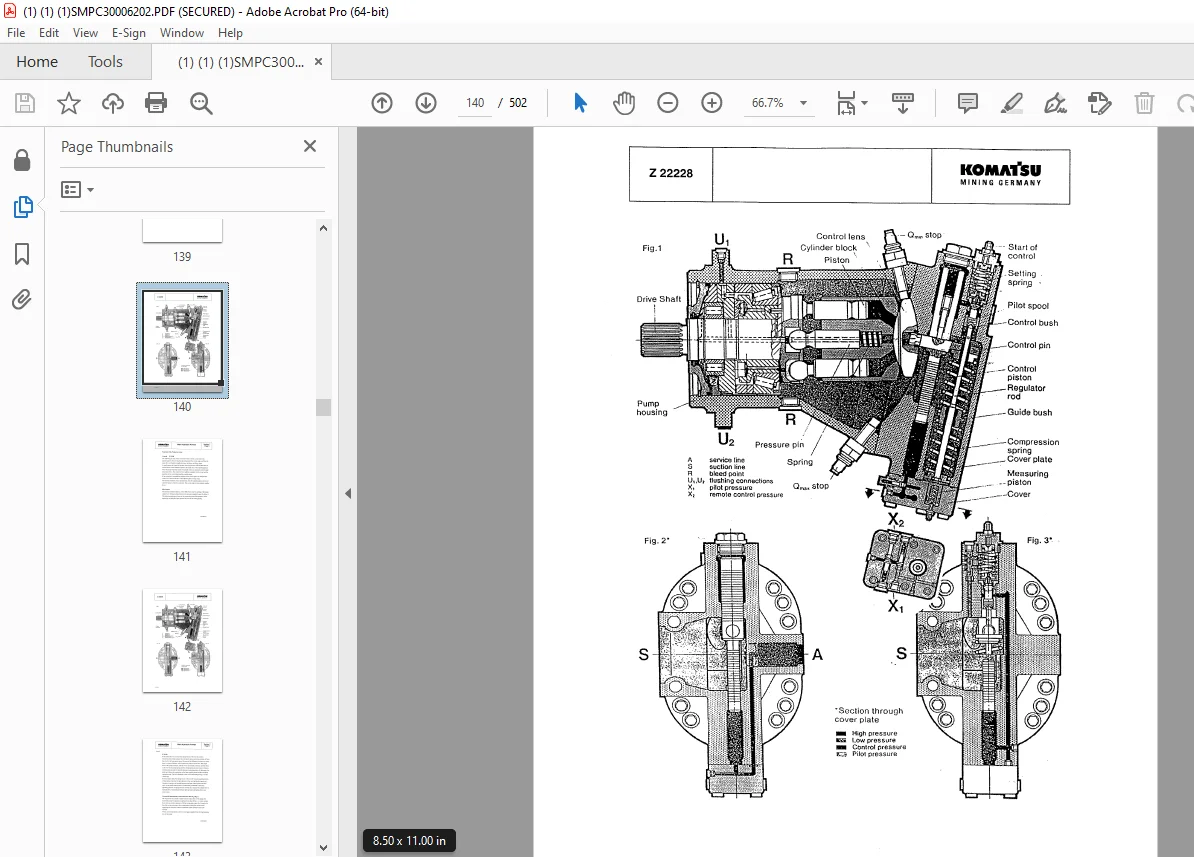
Function of the Pump Governor .141
Pump Bearing Lubrication 147
Pump Governor Adjustments .151
Measuring and setting pressure of the pressure cut-off valves .151
Measuring / Setting of the Start of De-stroking of the Main Pump 155
Adjusting the Damper Bolt .157
Pump Regulation, General 159
Determination of the Peak Point (Corner Value) 165
Hydraulic regulation adjustment, Stop Gap Operation .167
Detailed Explanation for the Electronic Regulation 169
Adjustments / Checks for the Electronic Regulation 171
Adjusting the RPM Sensor (MPU) 173
Adjustments at the ELL Module .175
Testing and Setting for the Complete Regulation .177
Checks / Function Test / Fault Finding at JOB SITE 179
EPM – module, Function and Test .181
ERM – module, Function and Test .183
ELL – module, Function and Test .187
Testing the Proportional Amplifier Module, A36 191
Simplified Trouble Shooting of the Electronic Control .193
Section 8 – Operating Hydraulic .197
Table of Contents, Section 8 197
Hydraulic for Attachment Cylinder .199
Attachments for Attachment Cylinder Hydraulic .203
Swing Circuit, General 221
Swing Motor .225
Swing Gear and Swing Parking Brake 229
Swing Brake Valve .233
Swing, Function .237
Function: R.H. rotation 237
Swinging Down Path (Delay) 239
Anticavation Circuit 241
Braking .243
Swing Parking Brake .245
Checks and Adjustments 247
Performance check of swing parking brake (house brake) 247
Adjustments for the Swing Circuit .249
High pressure check / adjustment 249
Low pressure check / adjustment .251
Checking the pilot pressure for the swing brake .253
Travel Circuit 255
Rotary Distributor 259
Travel Motor (Axial Piston Motor A2FM) 261
Travel Gear and Parking Brake .265
Travel Gear .265
Travel Parking Brake 267
Travel, Function 269
Anti-Cavitation Circuit .273
Adjustments / Checks 275
Untitled 279
Section 9 – Hydraulic Track Tension System 281
Table of Contents, Section 9 281
Hydraulic Track Tension System 283
Function 285
Pressure Increasing Valve Type: MO 7010 .289
Pressure Relief Valve, Direct Operated Type: DBD S 291
Adjustments / Pressure Checks .293
Basic Adjustment 295
Setting Procedure .297
Function Check 299
Section 10 – Access Ladder Hydraulic Operated .301
Table of Contents, Section 10 .301
Access Ladder Hydraulic Operated 303
Section 11 – Central Refilling System .307
Table of Contents, Section 11 .307
Central Refilling System 309
Section 12 – Hints for the Hydraulic Circuit Diagram 313
Table of Contents, Section 12 .313
Hints for Reading the Circuit Diagram .317
Legend of the Hydraulic Circuit Diagram .318
Pressure Check Points .322
How to Read the Circuit Diagram .325
Hydraulic Diagrams – 927 026 40 .327
Hydraulic Diagrams – 927 026 40 (1/4 327
Hydraulic Diagrams – 927 026 40 (2/4 328
Hydraulic Diagrams – 927 026 40 (3/4 329
Hydraulic Diagrams – 927 026 40 (4/4 330
Section 13 – Hints for the Electric Circuit Diagram .340
Table of Contents, Section 13 .340
Marking of Electrical Components in the Circuit Diagrams 341
Symbols .343
KMG Circuit Diagrams, General Information .347
Explanation of the Drawing Concept 349
Location of the Main Terminal Boxes ans some Important Components .351
Reading a Circuit Diagram .355
Adjustments .359
Electrical Circuit Diagrams – 927 027 40 366
Electrical Circuit Diagrams – 927 027 40 (1/72) .366
Electrical Circuit Diagrams – 927 027 40 (2/72) .367
Electrical Circuit Diagrams – 927 027 40 (3/72) .368
Electrical Circuit Diagrams – 927 027 40 (4/72) .369
Electrical Circuit Diagrams – 927 027 40 (5/72) .370
Electrical Circuit Diagrams – 927 027 40 (6/72) .371
Electrical Circuit Diagrams – 927 027 40 (7/72) .372
Electrical Circuit Diagrams – 927 027 40 (8/72) .373
Electrical Circuit Diagrams – 927 027 40 (9/72) .374
Electrical Circuit Diagrams – 927 027 40 (10/72) 375
Electrical Circuit Diagrams – 927 027 40 (11/72) 376
Electrical Circuit Diagrams – 927 027 40 (12/72) 377
Electrical Circuit Diagrams – 927 027 40 (13/72) 378
Electrical Circuit Diagrams – 927 027 40 (14/72) 379
Electrical Circuit Diagrams – 927 027 40 (15/72) 380
Electrical Circuit Diagrams – 927 027 40 (16/72) 381
Electrical Circuit Diagrams – 927 027 40 (17/72) 382
Electrical Circuit Diagrams – 927 027 40 (18/72) 383
Electrical Circuit Diagrams – 927 027 40 (19/72) 384
Electrical Circuit Diagrams – 927 027 40 (20/72) 385
Electrical Circuit Diagrams – 927 027 40 (21/72) 386
Electrical Circuit Diagrams – 927 027 40 (22/72) 387
Electrical Circuit Diagrams – 927 027 40 (23/72) 388
Electrical Circuit Diagrams – 927 027 40 (24/72) 389
Electrical Circuit Diagrams – 927 027 40 (25/72) 390
Electrical Circuit Diagrams – 927 027 40 (26/72) 391
Electrical Circuit Diagrams – 927 027 40 (27/72) 392
Electrical Circuit Diagrams – 927 027 40 (28/72) 393
Electrical Circuit Diagrams – 927 027 40 (29/72) 394
Electrical Circuit Diagrams – 927 027 40 (30/72) 395
Electrical Circuit Diagrams – 927 027 40 (31/72) 396
Electrical Circuit Diagrams – 927 027 40 (32/72) 397
Electrical Circuit Diagrams – 927 027 40 (33/72) 398
Electrical Circuit Diagrams – 927 027 40 (34/72) 399
Electrical Circuit Diagrams – 927 027 40 (35/72) 400
Electrical Circuit Diagrams – 927 027 40 (36/72) 401
Electrical Circuit Diagrams – 927 027 40 (37/72) 402
Electrical Circuit Diagrams – 927 027 40 (38/72) 403
Electrical Circuit Diagrams – 927 027 40 (39/72) 404
Electrical Circuit Diagrams – 927 027 40 (40/72) 405
Electrical Circuit Diagrams – 927 027 40 (41/72) 406
Electrical Circuit Diagrams – 927 027 40 (42/72) 407
Electrical Circuit Diagrams – 927 027 40 (43/72) 408
Electrical Circuit Diagrams – 927 027 40 (44/72) 409
Electrical Circuit Diagrams – 927 027 40 (45/72) 410
Electrical Circuit Diagrams – 927 027 40 (46/72) 411
Electrical Circuit Diagrams – 927 027 40 (47/72) 412
Electrical Circuit Diagrams – 927 027 40 (48/72) 413
Electrical Circuit Diagrams – 927 027 40 (49/72) 414
Electrical Circuit Diagrams – 927 027 40 (50/72) 415
Electrical Circuit Diagrams – 927 027 40 (51/72) 416
Electrical Circuit Diagrams – 927 027 40 (52/72) 417
Electrical Circuit Diagrams – 927 027 40 (53/72) 418
Electrical Circuit Diagrams – 927 027 40 (54/72) 419
Electrical Circuit Diagrams – 927 027 40 (55/72) 420
Electrical Circuit Diagrams – 927 027 40 (56/72) 421
Electrical Circuit Diagrams – 927 027 40 (57/72) 422
Electrical Circuit Diagrams – 927 027 40 (58/72) 423
Electrical Circuit Diagrams – 927 027 40 (59/72) 424
Electrical Circuit Diagrams – 927 027 40 (60/72) 425
Electrical Circuit Diagrams – 927 027 40 (61/72) 426
Electrical Circuit Diagrams – 927 027 40 (62/72) 427
Electrical Circuit Diagrams – 927 027 40 (63/72) 428
Electrical Circuit Diagrams – 927 027 40 (64/72) 429
Electrical Circuit Diagrams – 927 027 40 (65/72) 430
Electrical Circuit Diagrams – 927 027 40 (66/72) 431
Electrical Circuit Diagrams – 927 027 40 (67/72) 432
Electrical Circuit Diagrams – 927 027 40 (68/72) 433
Electrical Circuit Diagrams – 927 027 40 (69/72) 434
Electrical Circuit Diagrams – 927 027 40 (70/72) 435
Electrical Circuit Diagrams – 927 027 40 (71/72) 436
Electrical Circuit Diagrams – 927 027 40 (72/72) 437
Section 14 – Electronic Text Monitoring System 439
Table of Contents, Section 14 .439
Introduction 440
Function 443
Layout of Dash Board 449
Text Monitoring System 455
Function of Keys 1 to 8 of Keyboard .457
System Components .459
Switches for Adjustments of the ETM .461
Message Classification 461
Functions of ETM System and their Utilizations 463
Basic Display (Message #0) 463
Steps for Operating the ETM Keyboard 464
Call Up Basic Display from any Message 464
Call Up Message with Basic Display on Screen (A) 465
Display Content of Record (PROTOCOL) Memory .467
Display Content of Statistic Memory .469
Print Out Content of Statistics Memory 470
Print Out Content of Record (PROTOCOL) Memory .470
Print Out the Last Entries of Record (PROTOCOL) Memory 472
Change-Over from English to German Language .473
Change-Over from German to English Language .473
Several Message Conditions Occur at the Same Time .474
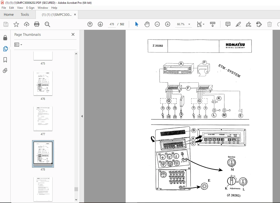
Settings of the Text Display Unit .477
Return to System Level 480
Setting Screen Brightness .480
Grouping of Message Numbers in the Input Signal Modules .481
Table of Messages .482
Basic Display (Message Page #0) .482
Message Pages 1 to 5 482
Message Pages 6 to 11 .483
Message Pages 12 to 18 484
Message Pages 19 to 26 485
Message Pages 27 to 30 486
Message Pages 31 to 38 487
Message Pages 39 to 44 488
Message Pages 45 to 52 489
Message Pages 53 to 64 490
Grouping of Messages According to their Priority 491
Explanation of Statistics Print-Out .495
Frequency / Voltage Converter (EFD-Module) 499
Function Control 501
Adjustment of the MPU .501
DESCRIPTION:
Komatsu PC3000-1 Hydraulic Mining Excavator Shop Manual SMPC30006202 – PDF DOWNLOAD
- SERIAL NUMBERS PC3000-1 6202
INTRODUCTION:
With this SERVICE MANUAL KOMATSU MINING GERMANY GmbH provides you with the description of the construction and the function of the major systems of the hydraulic excavator PC 3000.
We describe for you all functions and how to carry out the inspections and adjustments.
How do you find “your” desired information?
In the table of CONTENTS all the functions and components are shown in their sequence of the description.
G.B 31/12/24


