
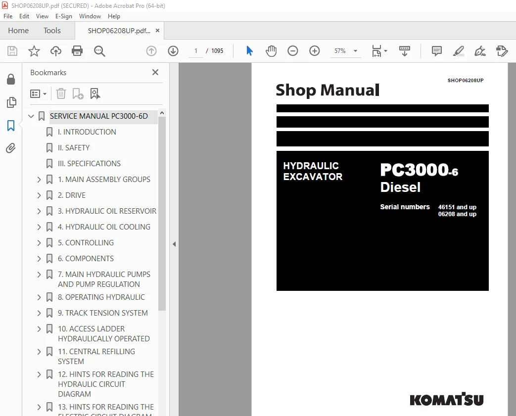
Komatsu PC3000-6 Diesel Excavator Shop Manual SHOP06208UP PDF
$36.95
Komatsu PC3000-6 Diesel Excavator Shop Manual SHOP06208UP – PDF DOWNLOAD
Description
Komatsu PC3000-6 Diesel Excavator Shop Manual SHOP06208UP – PDF DOWNLOAD
FILE DETAILS:
Komatsu PC3000-6 Diesel Excavator Shop Manual SHOP06208UP – PDF DOWNLOAD
Language : English
Pages : 1095
Downloadable : Yes
File Type : PDF
TABLE OF CONTENTS:
Komatsu PC3000-6 Diesel Excavator Shop Manual SHOP06208UP – PDF DOWNLOAD
06208 and up
SERVICE MANUAL PC3000-6D 0
I INTRODUCTION 5
II SAFETY 17
III SPECIFICATIONS 23
1 MAIN ASSEMBLY GROUPS 37
1 1 General layout 38
1 2 Superstructure 40
1 3 Power House 42
1 4 Hydraulic Oil Reservoir 44
1 5 Hydraulic Oil Cooler 46
1 6 Fuel tank (Fuel reservoir) 48
1 7 Counter weight 50
1 8 Cab support 52
1 9 Operators cab 54
1 10 Control blocks 56
1 11 Swing gears 58
1 12 Under carriage 60
2 DRIVE 63
2 1 Prime drive assembly 64
2 2 Engine and gearbox mount 66
2 3 Torque supports 69
2 4 Radiator fan Drive Assy 70
2 5 Pump distributor gearbox (PTO) 72
2 5 1 Spline shaft housing 74
2 5 2 PTO lubrication and cooling 76
2 5 3 PTO valve adjustments 78
2 6 Coupling 82
2 6 1 Rubber type coupling “Reich”, (replaces “Geislinger Coupling”) 82
2 6 2 Oil filled type coupling “Geisslinger” 84
2 7 Air cleaner 86
3 HYDRAULIC OIL RESERVOIR 89
3 1 Hydraulic oil reservoir 90
3 2 Return and leak oil filter 94
3 3 Breather Filter 98
3 4 Location of electrical components 100
4 HYDRAULIC OIL COOLING 103
4 1 General 104
4 2 Hydraulic oil cooling circuit 106
4 3 Back pressure valve adjustment 110
4 4 Fan drive 112
4 4 1 Fan pump 114
4 4 2 Pressure relieve valve 115
4 4 3 Temperature relay 117
4 5 Cooler fan drive adjustment 118
5 CONTROLLING 121
5 1 Pilot pressure supply and adjustment 122
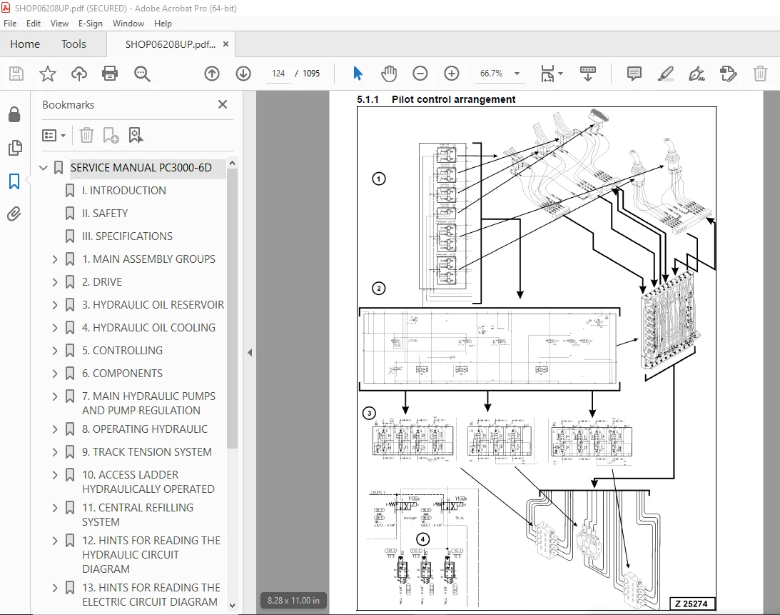
5 1 1 Pilot control arrangement 124
5 1 2 Pilot pressure adjustment 126
5 1 3 Check of Control Pressure 128
5 2 Slew brakes 130
5 3 Travel parking brake 133
5 4 Check of the pilot control logic 135
5 4 1 Check sheet FSA Page 1 137
5 4 2 Check sheet BHA Page 1 150
6 COMPONENTS 159
6 1 Main control block and valve arrangement 160
6 1 1 FSA arrangement 162
6 1 2 BHA arrangement 166
6 2 Distributor manifold 170
6 2 1 Front shovel attachment FSA 170
6 2 2 Back hoe attachment BHA 172
6 2 3 SRV with throttle check valve 174
6 2 4 Anti cavitation valve (check valve) 176
6 3 Main control block 178
6 3 1 Load holding valve 184
6 3 2 High pressure filter 186
6 3 3 Pressure relieve valves and anti-cavitation valve 188
6 3 4 Pressure relieve valves and anti-cavitation valve 190
6 4 Compact valve blocks 192
6 5 Compact valve blocks 194
6 6 Auxiliary gear pumps 196
6 7 Hydraulic cylinder 198
6 8 Swing ring 200
7 MAIN HYDRAULIC PUMPS AND PUMP REGULATION 203
7 1 General 204
7 1 1 Pump location 206
7 2 Main pump operating principles 208
7 2 1 Main pump function 213
7 3 Main pump checks and adjustments 216
7 3 1 Peak point diesel engine test 216
7 3 2 Pressure transducer test 218
7 3 3 Cut off function 219
7 3 4 Pump regulation 221
7 3 5 Swing pump volume reduction 222
7 4 Electronic pump regulation 223
7 5 Pump Controller CR700 226
7 6 Multi Monitor 228
7 7 Multimonitor software instruction 230
7 7 1 Multimonitor main control 230
7 7 2 Service Menu screen 230
7 7 3 Monitoring (menu item 01) 231
7 7 4 Abnormality Record (menu item 02) 232
7 7 5 Default (menu item 03) 235
7 7 6 Adjustment (menu item 04) 236
7 7 7 Display Setup (menu item 05) 238
7 7 8 Table of fault messages and adjustments 239
7 8 Trouble shooting pump and pump regulation 248
8 OPERATING HYDRAULIC 249
8 1 General layout 250
8 2 Floating function of boom and stick only FSA 254
8 3 Check and Adjustments for MRV’s and SRV’s 256
8 3 1 Check and Adjustments for MRV 258
8 3 2 Check and Adjustment for SRV’s 260
8 3 3 Check and adjustment of the throttle check valves 268
8 4 Hydraulic for the swing circuit 270
8 4 1 Hydraulic for the swing circuit 274
8 4 2 Slew gear box L & S 278
8 4 3 Slew parking brake 282
8 4 4 Slew service brake valve 286
8 4 5 Checks and adjustment of the slew pressure valve 291
8 5 Travel circuit 294
8 5 1 Rotary joint 296
8 5 2 Travel motor A2FMt 298
8 5 3 Travel gear 300
8 5 4 Travel parking brake 302
8 5 5 Travel control function 304
8 5 6 Check and Adjustment SRV travel system 307
9 TRACK TENSION SYSTEM 309
9 1 General layout 310
9 2 Track tensioning function 312
9 2 1 Cushioning 314
9 2 2 Pressure Increasing valve PIV 316
9 3 Track tensioning adjustment 320
9 3 1 Track tensioning function check 322
10 ACCESS LADDER HYDRAULICALLY OPERATED 325
10 1 Access ladder 326
10 2 Access ladder functional description 328
11 CENTRAL REFILLING SYSTEM 333
11 0 1 Functional description 334
12 HINTS FOR READING THE HYDRAULIC CIRCUIT DIAGRAM 339
12 1 General 340
12 2 Symbolic 342
12 2 1 Lines, unions 343
12 2 2 Components, valves 345
12 2 3 Sensors 345
12 2 4 Valves, valve components 346
12 2 5 Pump, motor, cylinder 350
13 HINTS FOR READING THE ELECTRIC CIRCUIT DIAGRAM 355
13 1 Designation of electrical components 357
13 2 Electric symbols 358
13 3 Symbols 360
13 3 1 Drawing concept 362
13 3 2 Reading of the circuit diagram 368
14 ELECTRONIC TEXT MONITORING SYSTEM ETM 373
14 1 General Function 374
15 AUTOMATIC LUBRICATION SYSTEM 377
15 1 General Function 378
15 2 Function of a lubrication cycle 380
15 3 Lubrication pump drive 388
15 4 Lubrication pump 390
15 4 1 Adjustments lubricating pump speed 392
15 4 2 Adjustments lubricating pump pressure 394
15 5 Lubricant Injector (metering valve) 396
15 5 1 Connection of one or more injectors 398
15 5 2 Function lubrication injector (metering valve) 400
15 6 End line pressure switch 404
15 7 Lubricant in line filter 406
15 8 Lubricant level sensor 408
15 8 1 Capacitive digital type for machines with ETM 408
15 8 2 Capacitive analog type for machines with PLC 410
15 9 Lubrication system function and controlling 412
15 9 1 Central Lubrication System (CLS) function and controlling with ETM system (PC 3000) 414
15 9 2 Swing ring lubrication system (SLS) function and controlling with ETM system (PC3000) 418
15 10 Adjustment of the lubrication system with ETM 425
15 11 Trouble shooting lubricating system 426
15 11 1 Lubrication pump cylinder does not move 427
15 11 2 Lubricant pressure built up very slowly or not at all 429
15 11 3 Insufficient lubricant supply to one or more attachment bearings 429
15 11 4 Insufficient lubricant at the swing ring gear 431
DISASSEMBLY AND ASSEMBLY PC3000-6D 0
1 INTRODUCTION 453
1 1 Contents of the binder 454
1 2 Foreword 455
1 2 1 Service 27
2 SAFETY 457
2 1 Safety Instructions 458
2 1 1 Method of using this manual 458
2 1 2 General precautions 460
2 1 3 Preparations for work 461
2 1 4 Precautions during work 462
2 1 5 WARNING OF SPECIAL DANGERS 464
2 1 5 1 ELECTRICAL ENERGY 464
2 1 5 2 GAS, DUST, STEAM AND SMOKE 465
2 1 5 3 HYDRAULIC, AIR CONDITIONING AND PNEUMATIC EQUIPMENT 466
2 1 5 4 NOISE 466
2 1 5 5 Heat 467
2 1 5 6 OIL, GREASE AND OTHER CHEMICAL SUBSTANCES 467
2 1 5 7 Height 467
2 1 6 SPECIAL SAFETY EQUIPMENT 469
2 1 6 1 SAFETY HARNESS IN CONFORMITY WITH EN 361 (EUROPEAN STANDARD) 469
2 1 6 2 INSTRUCTIONS FOR USE 471
2 1 6 3 RECOMMENDATIONS FOR USE OF THE HOLDING HOOKS AND HOLD-BACK HOOKS OF THE SAFETY HARNESS 473
2 1 6 4 INSTRUCTIONS FOR USE 475
2 2 Lifting Gears 476
2 2 1 Wire ropes 476
2 2 2 Sling accessory 478
2 2 3 Weight tables 479
2 2 3 1 Superstructure 479
2 2 3 2 Undercarriage 481
2 2 3 3 Attachment 482
2 3 Torque charts according to DIN 483
2 3 1 Metric standard thread 483
2 3 2 Metric fine thread 484
2 3 3 Cummins motor torques – metric 485
2 3 4 Cummins motor torques – U S Customary 485
2 3 5 Flange connections 486
2 4 Conversation table 487
2 4 1 Method of using the conversation table 487
2 4 2 Millimeter – Inch & Kilogram – Pound 488
2 4 3 Liter – U S Gallon & Liter – U K Gallon 489
2 4 4 KGm – ft lb 490
2 4 5 bar – PSI / PSI – bar 491
2 4 6 Basic Values in Ohm according to DIN 43 76 492
2 4 7 Temperature 493
2 5 Explanation of abbreviations 494
3 SUPERSTRUCTURE 495
3 1 Diesel Engine 496
3 1 1 Removal of the Diesel engine 496
3 1 2 Replacement of the Diesel engine 502
3 1 3 Engine torque support and engine/PTO mounts 504
3 1 3 1 Flexible mounts 505
3 1 3 2 Torque support 507
3 1 4 Alternator 508
3 1 4 1 Removal of the alternator 508
3 1 4 2 Replacement of the alternator 510
3 1 5 Batteries 511
3 1 5 1 Removal of the batteries 511
3 1 5 2 Replacement of the batteries 513
3 1 6 Radiator fan 514
3 1 6 1 Removal of the radiator fan 515
3 1 6 2 Replacement of the radiator fan 516
3 1 7 Radiator 517
3 1 7 1 Removal of the Radiator 517
3 1 7 2 Replacement of the radiator 520
3 1 8 Starter system 521
3 1 8 1 Removal of the starter motor 521
3 1 8 2 Replacement of the starter motor 522
3 1 9 Geislinger coupling 524
3 1 9 1 Removal of the Geislinger coupling 526
3 1 9 2 Replacement of the Geislinger coupling 528
3 2 PTO 529
3 2 1 Main pumps 529
3 2 1 1 Preparatory works for main pump removal 531
3 2 1 2 Removal of Main Pump 1 535
3 2 1 3 Replacement of main pump 1 537
3 2 1 4 Removal of Main Pump 2 538
3 2 1 5 Replacement of main pump 2 541
3 2 1 6 Removal of Main Pump 3 542
3 2 1 7 Replacement of main pump 3 545
3 2 2 PTO oil circulation pump (auxiliary pump) 546
3 2 2 1 Removal of the oil circulation pump (auxiliary pump) 546
3 2 2 2 Replacement of the oil circulation pump (auxiliary pump) 547
3 2 3 Pump distributor gearbox (PTO) 548
3 2 3 1 Removal of the Pump distributor gearbox (PTO) 550
3 2 3 2 Replacement of the Pump distributor gearbox (PTO) 553
3 3 Hydraulics 554
3 3 1 Hydraulic cooler fan Drive Pump 554
3 3 1 1 Removal of hydraulic cooler fan drive pump 554
3 3 2 Replacement of hydraulic cooler fan drive pump 556
3 3 3 Hydraulic Cooler Fan Assembly 557
3 3 3 1 Removal of hydraulic cooler fan assembly 557
3 3 3 2 Replacement of hydraulic cooler fan assembly 560
3 3 3 3 Removal of hydraulic cooler Fan and motor 562
3 3 3 4 Replacement of hydraulic cooler Fan and motor 563
3 3 4 Hydraulic Oil Coolers 564
3 3 4 1 Removal of the hydraulic oil coolers 567
3 3 4 2 Replacement of the oil hydraulic cooler 570
3 3 4 3 Removal of the hydraulic oil cooler frame 572
3 3 4 4 Replacement of the hydraulic oil cooler frame 576
3 3 5 Main Relief Valves (MRV) 577
3 3 5 1 Removal of the MRV 577
3 3 5 2 Replacement of the MRV 579
3 3 6 pilot oil pump (Gear pump) 580
3 3 6 1 Removal of the pilot oil pump 581
3 3 6 2 Replacement of the pilot oil pump 582
3 3 7 Main Gate Valve 583
3 3 7 1 Removal of the main gate valve 583
3 3 7 2 Replacement of the main gate valve 584
3 3 8 Hydraulic Oil Reservoir 586
3 3 8 1 Removal of the hydraulic oil reservoir 588
3 3 8 2 Replacement of the hydraulic oil reservoir 596
3 3 9 Main Control Valve Blocks 599
3 3 9 1 Removal of the main control valve blocks 603
3 3 9 2 Replacement of the main control valve blocks 607
3 3 10 Service line Relief Valves (SRV) 608
3 3 10 1 Removal of SRV on main Control valve block 608
3 3 10 2 Replacement of SRV on main control valve blocks 611
3 3 11 Anti-cavitation Valves (ACV) 612
3 3 11 1 Removal of ACV on Manifold 613
3 3 11 2 Replacement of ACV on Manifold 617
3 3 11 3 Removal of ACV on main control valve blocks 619
3 3 11 4 Replacement of ACV on main control valve blocks 621
3 3 12 Throttle check valves 622
3 3 12 1 Removal of throttle check valves) 624
3 3 12 2 Replacement of throttle check valves 627
3 3 13 manifold 628
3 3 13 1 Removal of the manifold 628
3 3 13 2 Replacement of the manifold 630
3 3 13 3 Removal of Diffuser on Manifold 631
3 3 13 4 Replacement of Diffuser on Manifold 633
3 4 Slew Drive 635
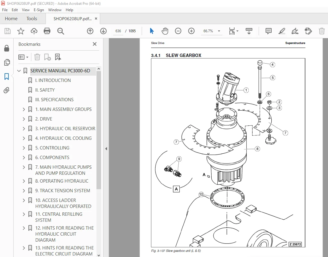
3 4 1 Slew GearBox 636
3 4 1 1 Removal of the slew gearbox 637
3 4 1 2 Replacement of the slew gearbox 641
3 4 2 Swing Motor 643
3 4 2 1 Removal of the swing motor 644
3 4 2 2 Replacement of the swing motor 646
3 4 3 Slew parking brake 647
3 4 3 1 Removal/Disassembly of the parking brake 649
3 4 3 2 Replacement/assembly of the slew parking brake 652
3 4 4 Dynamic Slew Brake 654
3 4 4 1 Removal of the slew service brake valve 657
3 4 4 2 Replacement of the slew service brake valve 659
3 4 5 Swing circle lubrication pinion 660
3 4 5 1 Removal of the lubrication pinion assembly 662
3 4 5 2 Replacement of the lubrication pinion assembly 664
3 5 Lubrication pumps 665
3 5 1 Removal of the Lubrication pump 665
3 5 2 Replacement of the lubricating pump 667
3 6 Pump controller CR700 668
3 6 1 Removal of the pump controller CR700 668
3 6 2 Replacement of the pump controller CR700 669
3 7 Operator’s Cab 670
3 7 1 Removal of the operator’s cab 672
3 7 2 Replacement of the operator’s cab 676
3 7 3 Cab mounts 677
3 7 3 1 Removal of the cab mounts 677
3 7 3 2 Replacement of the cab mounts 678
3 7 4 FRONT WINDOW 679
3 7 4 1 Removal of the Front window 679
3 7 4 2 Replacement of the front window 680
3 7 5 Operator’s seat 681
3 7 5 1 Removal of the operator’s seat 681
3 7 5 2 Replacement of the operator’s seat 682
3 7 6 ETM 683
3 7 6 1 Removal of the ETM 683
3 7 6 2 Replacement of the ETM 683
3 7 7 Access Ladder 684
3 7 7 1 Removal of access Ladder 685
3 7 7 2 Replacement of access ladder 687
3 7 7 3 Removal of access ladder cylinder 688
3 7 7 4 Replacement of access ladder cylinder 689
3 7 8 Removal of the cab base 690
3 7 9 Replacement of the cab base 692
3 8 CounterWeight 694
3 8 1 Removal of the counterweight 696
3 8 2 Replacement of the counterweight 698
3 9 Superstructure Lifting 699
3 9 1 Remove the Superstructure from the Undercarriage 699
3 9 2 Install the Superstructure onto the undercarriage 703
3 10 Fuel Tank 706
3 10 1 Removal of the Fuel tank 707
3 10 2 Replacement of the Fuel tank 711
4 UNDERCARRIAGE 713
4 1 Travel system 714
4 1 1 Track group 714
4 1 1 1 Substitute the track group 714
4 1 2 Sprocket 719
4 1 2 1 Removal of the sprocket 719
4 1 2 2 Replacement of the sprocket 721
4 1 3 Guide wheels 722
4 1 3 1 Removal of the guide wheel assembly 722
4 1 3 2 Replacement of the guide wheel assembly 723
4 1 4 Track tensioning accumulators 724
4 1 4 1 Removal of the low pressure accumulators 724
4 1 4 2 Replacement of the low pressure accumulators 726
4 1 4 3 Removal of the high pressure accumulators 727
4 1 4 4 Replacement of the high pressure accumulators 728
4 1 5 Track tension valve block 729
4 1 5 1 Removal of the track tensioning valve block 729
4 1 5 2 Replacement of the track tensioning valve block 730
4 1 6 Hydraulic hoses of the track tensioning system 731
4 1 6 1 Substitute THE HYDRAULIC HOSES 731
4 1 7 Travel brake valve block (overspeed valve) 734
4 1 7 1 Removal of the travel brake valve block 735
4 1 7 2 Replacement of the travel brake valve block 736
4 1 8 Track tensioning cylinders 737
4 1 8 1 Removal of the track tensioning cylinders 737
4 1 8 2 Replacement of the track tensioning cylinders 738
4 1 9 Travel motor 739
4 1 9 1 Removal of the travel motors 739
4 1 9 2 Replacement of the travel motors 743
4 1 10 travel parking brake 744
4 1 10 1 Removal of the travel parking brake 746
4 1 10 2 Replacement of the travel parking brake 748
4 1 11 Travel gearbox 750
4 1 11 1 Removal of the travel gearbox 751
4 1 11 2 Replacement of the travel gearbox 755
4 1 12 Carrier roller 756
4 1 12 1 Removal of the carrier roller assembly 756
4 1 12 2 Replacement of the carrier roller assembly 758
4 1 13 Track roller 760
4 1 13 1 Removal of the Track roller assembly 760
4 1 13 2 Replacement of the Track roller assembly 761
4 2 Car body 762
4 2 1 Removal of the car body 762
4 2 2 Replacement of the car body 767
4 2 2 1 Tightening torqe for the crawler carrier mounting bolts 772
4 2 3 Rotary joint 776
4 2 3 1 Removal of the rotary joint 778
4 2 3 2 Replacement of the rotary joint 781
4 2 4 swing circle 782
4 2 4 1 Removal of the swing circle 784
4 2 4 2 Replacement of the swing circle 786
5 ATTACHMENT 791
5 1 Backhoe 792
5 1 1 Cylinder bypass test 794
5 1 2 Boom 796
5 1 2 1 Removal of the Boom 796
5 1 2 2 Replacement of the boom 800
5 1 2 3 Removal of boom cylinders 802
5 1 2 4 Replacement of boom cylinders 807
5 1 3 Stick 810
5 1 3 1 Removal of the Stick 810
5 1 3 2 Replacement of Stick 814
5 1 3 3 Removal of Stick Cylinders 816
5 1 3 4 Replacement of Stick cylinders 820
5 1 4 Bucket 824
5 1 4 1 Removal of the bucket 824
5 1 4 2 Replacement of the bucket 827
5 1 4 3 Removal of Bucket Cylinders 828
5 1 4 4 Replacement of Bucket Cylinders 834
5 1 5 Bucket link rod and steering rods 836
5 1 5 1 Removal of the bucket link rod 836
5 1 5 2 Replacement of the bucket link rod 838
5 1 5 3 Removal of the steering rods 839
5 1 5 4 Replacement of the steering rod 841
5 1 6 Ground engaging tools (GET) 842
5 1 6 1 Removal and replacement of the GET 842
5 1 7 Hydraulic hoses at the attachment 844
5 1 7 1 Substitute the boom arc hoses 844
5 1 7 2 Substitute the boom cylinder hoses 848
5 1 7 3 Substitute the stick cylinder hoses 852
5 1 7 4 Substitute the bucket cylinder hoses 856
5 1 8 metering valves (grease injectors) at the attachment 860
5 1 8 1 Removal of the metering valves (grease injectors) 860
5 1 8 2 Replacement of the metering valves (grease injectors) 861
6 APPENDIX 863
6 1 Fuel and Lubricants 864
6 2 Filling capacities 866
6 3 Tools lists 868
6 3 1 used Special tools (Overview) 868
6 3 2 Komatsu Tools catalogue 871
6 4 Work instructions 908
6 4 1 Surface coating with INTERZINC 697 908
6 4 2 Remove / install the crawler carrier 910
6 4 3 Use of the hydraulic torque wrench (supplier’s documentation) 911
6 5 Service Bulletins 939
6 5 1 AH00511 941
6 5 2 AH00519 963
6 5 3 AH01518 969
6 5 4 AH01521a 973
6 5 5 AH01531A 985
6 5 6 AH02513b 997
6 5 7 AH02521b 1003
6 5 8 AH03509a 1011
6 5 9 AH03510 1039
6 5 10 AH04518 1059
6 5 11 AH05503 1063
6 5 12 AH05546 1077
6 5 13 AH06524 1081
6 5 14 AH06530 1085
6 5 15 AH07526 1089
DESCRIPTION:
Komatsu PC3000-6 Diesel Excavator Shop Manual SHOP06208UP – PDF DOWNLOAD
06208 and up
When removing the oil filler cap, drain plug or hydraulic pressure measuring plugs, loosen them slowly to prevent the oil from spurting out. The water and oil in the circuits are hot when the engine is stopped, so be careful not to get burned. Wait for the oil and water to cool before carrying out work on the oil or water circuits.
Before starting work, remove the leads from the battery. ALWAYS remove the lead from the negative (-) terminal first.
When raising heavy components, use a hoist or crane.
Check that the wire rope, chains and hooks are free from damage.
Always use lifting equipment which has ample capacity.
Install the lifting equipment at the correct places. Use a hoist or crane and operate slowly to prevent the component from
hitting any other part. Do not work with any part still raised by the hoist or crane.
When removing covers which are under internal pressure or under pressure from a spring, always leave two bolts in position on opposite sides. Slowly release the pressure, then slowly loosen the bolts to remove.
When removing components, be careful not to break or damage the wiring, Damaged wiring may cause electrical fires.
When removing piping, stop the fuel or oil from spilling out. If any fuel or oil drips on to the floor, wipe it up immediately. Fuel or oil on the floor can cause you to slip, or can even start fires.
As a general rule, do not use gasoline to wash parts.
Be sure to assemble all parts again in their original places. Replace any damaged part with new parts.
When installing hoses and wires, be sure that they will not be damaged by contact with other parts when the machine is being operated.
When installing high pressure hoses, make sure that they are not twisted. Damaged tubes are dangerous, so be extremely careful when installing tubes for high pressure circuits. Also check that connecting parts are correctly installed.
When aligning two holes, never insert your fingers or hand. Be careful not to get your fingers caught in a hole.
IMAGES PREVIEW OF THE MANUAL:
S.V 22/12/24



