Komatsu PC340-6K, PC340LC-6K, PC340NLC-6K Repair Manual PDF Download
Original price was: $69.95.$24.95Current price is: $24.95.
Komatsu PC340-6K, PC340LC-6K, PC340NLC-6K Hydraulic Excavator Shop Manual
MACHINE MODEL
PC340-6K
PC340LC-6K
PC340NLC-6K
SERIAL NUMBER
K32001 and up, K34001 and up
K32001 and up, K34001 and up
K32001 and up, K34001 and up
Description
Komatsu PC340-6K, PC340LC-6K, PC340NLC-6K Hydraulic Excavator Shop Manual
FILE DETAILS:
Komatsu PC340-6K, PC340LC-6K, PC340NLC-6K Hydraulic Excavator Shop Manual
File Format : PDF
Language : English
Printable : Yes
Searchable : Yes
Bookmarked : Yes
Product Code : UEBM000901
Total Pages : 748
DESCRIPTION:
Komatsu PC340-6K, PC340LC-6K, PC340NLC-6K Hydraulic Excavator Shop Manual
FOREWORD:
GENERAL:
This shop manual has been prepared as an aid to improve the quality of repairs by giving the serviceman an accurate understanding of the product and by showing him the correct way to perform repairs and make judgements. Make sure you understand the contents of this manual and use it to full effect at every opportunity. This shop manual mainly contains the necessary technical information for operations performed in a service workshop. For ease of understanding, the manual is divided into the following chapters: these chapters are further divided into the each main group of components.
STRUCTURE AND FUNCTION:
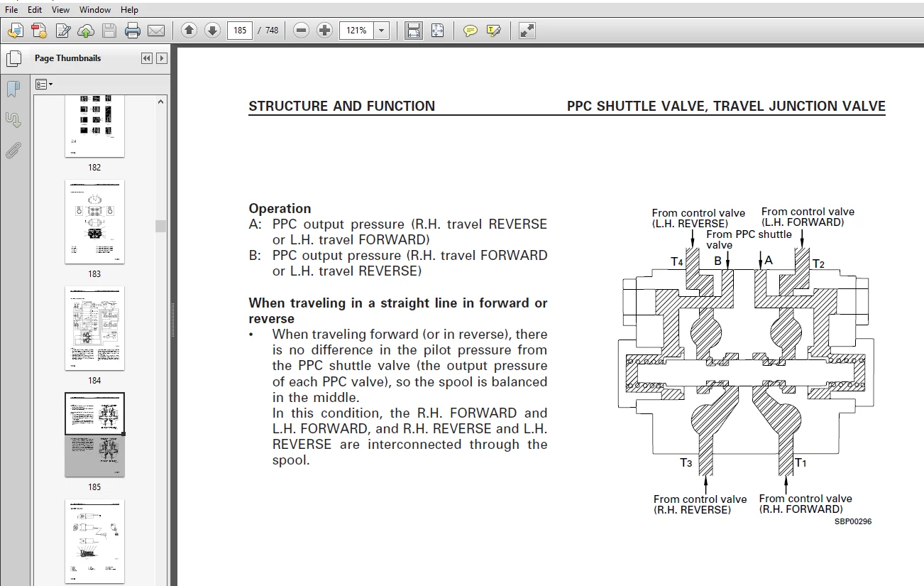
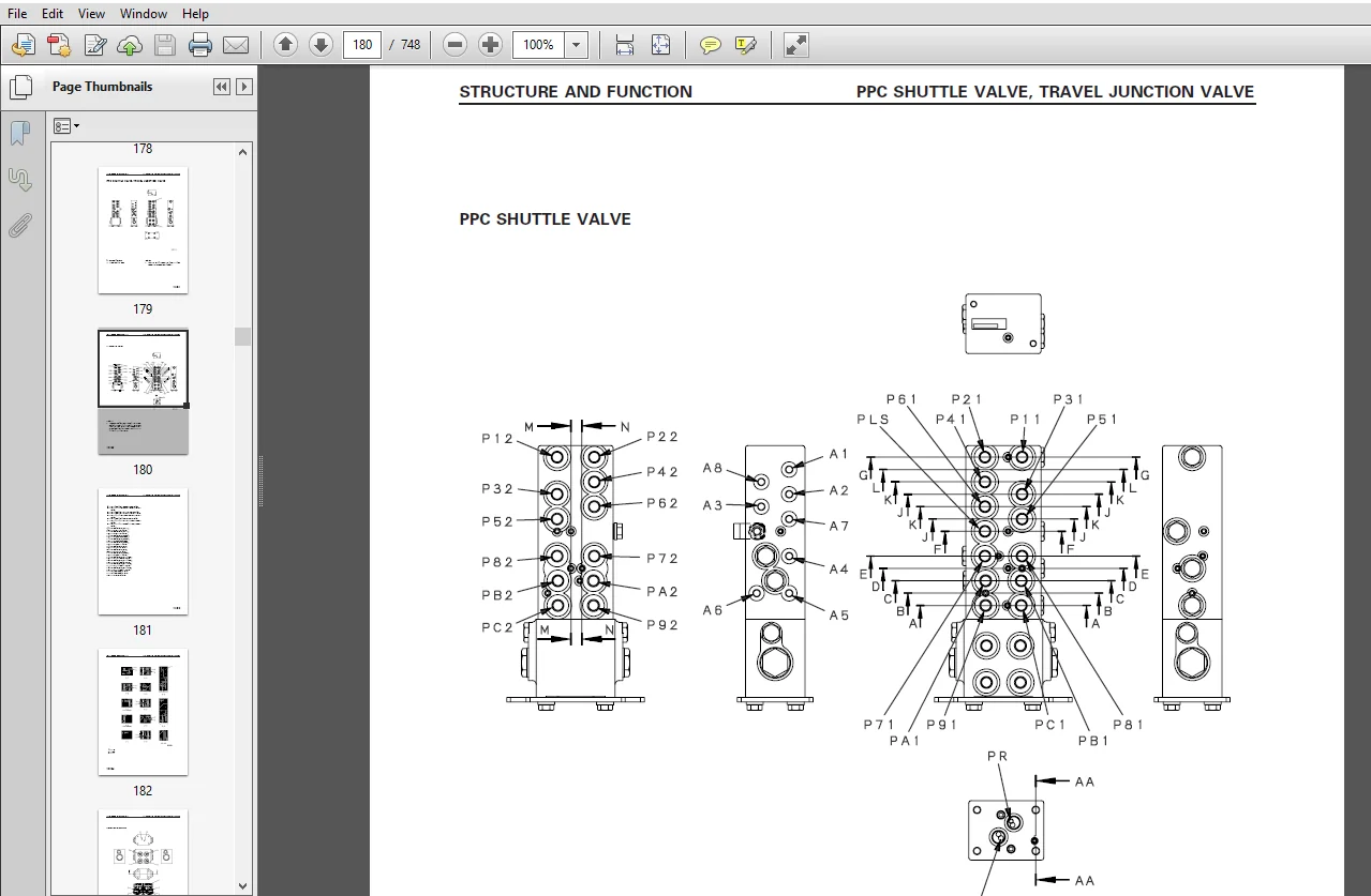
This section explains the structure and function of each component. It serves not only to give an understanding of the structure, but also serves as reference material for troubleshooting.
TESTING AND ADJUSTING:
This section explains checks to be made before and after performing repairs , as well as adjustments to be made at completion of the checks and repairs. Troubleshooting charts correlating “problems” to “Causes” are also included in this section.
DISASSEMBLY AND ASSEMBLY:
This section explains the order to be followed when removing, installing, disassembling or assembling eachr component, as well as precautions to be taken for these operations.
MAINTENANCE STANDARD:
This section gives the judgement standards when inspecting disassembled parts.
TABLE OF CONTENTS:
Komatsu PC340-6K, PC340LC-6K, PC340NLC-6K Hydraulic Excavator Shop Manual
SAFETY ........................................................................................................................................................................................................................  3
	SAFETY NOTICE .............................................................................................................................................................................................................  3
		SAFETY SAFETY NOTICE GENERAL PRECAUTIONS ..............................................................................................................................................................................  3
		PREPARATIONS FOR WORK. ................................................................................................................................................................................................  3
		SAFETY SAFETY NOTICE PRECAUTIONS DURING WORK ..........................................................................................................................................................................  4
FOREWORD ......................................................................................................................................................................................................................  5
	GENERAL ...................................................................................................................................................................................................................  5
		STRUCTURE AND FUNCTION ................................................................................................................................................................................................  5
		TESTING AND ADJUSTING .................................................................................................................................................................................................  5
		DISASSEMBLY AND ASSEMBLY ..............................................................................................................................................................................................  5
		MAINTENANCE STANDARD ..................................................................................................................................................................................................  5
		FOREWORD FOREWORD GENERAL VOLUMES .....................................................................................................................................................................................  6
		Chassis volume: .......................................................................................................................................................................................................  6
		Engine model: .........................................................................................................................................................................................................  6
		Electrical volume: Attachments volume: ................................................................................................................................................................................  6
		DISTRIBUTION AND UPDATING .............................................................................................................................................................................................  6
		FILING METHOD .........................................................................................................................................................................................................  6
		10 - 3 ................................................................................................................................................................................................................  6
		1 2 - 5 ...............................................................................................................................................................................................................  6
		REVISED EDITION MARK ..................................................................................................................................................................................................  6
		REVISIONS .............................................................................................................................................................................................................  6
		SYMBOLS ...............................................................................................................................................................................................................  6
		FOREWORD HOW TO READ THE SHOP MANUAL ..................................................................................................................................................................................  6
HOW TO READ THE SHOP MANUAL ...................................................................................................................................................................................................  6
HOISTING INSTRUCTIONS .........................................................................................................................................................................................................  7
COATING MATERIALS .............................................................................................................................................................................................................  8
STANDARD TIGHTENING TORQUE ....................................................................................................................................................................................................  9
ELECTRIC WIRE CODE ............................................................................................................................................................................................................ 11
CONVERSION TABLE .............................................................................................................................................................................................................. 12
GENERAL ....................................................................................................................................................................................................................... 19
	SPECIFICATION DRAWINGS .................................................................................................................................................................................................... 20
	FUEL, COOLANT AND LUBRICANTS .............................................................................................................................................................................................. 26
STRUCTURE AND FUNCTION ........................................................................................................................................................................................................ 29
	PARTS RELATED TO ENGINE ................................................................................................................................................................................................... 30
	RADIATOR, OIL COOLER ...................................................................................................................................................................................................... 32
	POWER TRAIN ............................................................................................................................................................................................................... 33
	FINAL DRIVE ............................................................................................................................................................................................................... 34
	SWING CIRCLE .............................................................................................................................................................................................................. 35
	SWING MACHINERY ........................................................................................................................................................................................................... 36
	TRACK FRAME, RECOIL SPRING ................................................................................................................................................................................................ 37
	TRACK SHOE ................................................................................................................................................................................................................ 38
	HYDRAULIC PIPING DRAWING .................................................................................................................................................................................................. 40
	HYDRAULIC CIRCUIT DIAGRAM ................................................................................................................................................................................................. 42
	HYDRAULIC PUMP ............................................................................................................................................................................................................ 45
	CONTROL VALVE ............................................................................................................................................................................................................. 66
	SELF- REDUCING PRESSURE VALVE SUCTION SAFETY VALVE ........................................................................................................................................................................ 81
CLSS .......................................................................................................................................................................................................................... 83
SWING MOTOR ...................................................................................................................................................................................................................148
CENTER SWIVEL JOINT ...........................................................................................................................................................................................................154
TRAVEL MOTOR ..................................................................................................................................................................................................................156
VALVE CONTROL .................................................................................................................................................................................................................165
WORK EQUIPMENT Ł SWING PPC VALVE ..............................................................................................................................................................................................166
TRAVEL PPC VALVE SERVICE PPC VALVE ............................................................................................................................................................................................174
PPC SAFETY LOCK VALVE .........................................................................................................................................................................................................177
PPC ACCUMULATOR ...............................................................................................................................................................................................................177
PPC SHUTTLE VALVE, TRAVEL JUNCTION VALVE ......................................................................................................................................................................................179
LS- EPC VALVE .................................................................................................................................................................................................................186
SOLENOID VALVE ................................................................................................................................................................................................................190
WORK EQUIPMENT ................................................................................................................................................................................................................198
AIR CONDITIONER ...............................................................................................................................................................................................................199
ACTUAL ELECTRIC WIRING DIAGRAM ................................................................................................................................................................................................200
ELECTRIC CIRCUIT DIAGRAM ......................................................................................................................................................................................................204
ENGINE CONTROL ................................................................................................................................................................................................................208
ELECTRONIC CONTROL SYSTEM .....................................................................................................................................................................................................215
MACHINE MONITOR SYSTEM ........................................................................................................................................................................................................242
TESTING AND ADJUSTING .........................................................................................................................................................................................................253
	STANDARD VALUE TABLE FOR ENGINE RELATED PARTS .............................................................................................................................................................................256
	STANDARD VALUE TABLE FOR CHASSIS RELATED PARTS ............................................................................................................................................................................257
	STANDARD VALUE TABLE FOR ELECTRICAL PARTS .................................................................................................................................................................................265
TOOLS FOR TESTING, ADJUSTING, AND TROUBLESHOOTING .............................................................................................................................................................................274
MEASURING ENGINE SPEED ........................................................................................................................................................................................................275
MEASURING EXHAUST COLOR .......................................................................................................................................................................................................276
ADJUSTING VALVE CLEARANCE .....................................................................................................................................................................................................277
MEASURING COMPRESSION PRESSURE ................................................................................................................................................................................................278
MEASURING BLOW- BY PRESSURE ...................................................................................................................................................................................................278
TESTING AND ADJUSTING FUEL INJECTION TIMING ...................................................................................................................................................................................279
MEASURING ENGINE OIL PRESSURE .................................................................................................................................................................................................280
TESTING AND ADJUSTING ALTERNATOR BELT TENSION .................................................................................................................................................................................281
TESTING AND ADJUSTING WATER PUMP BELT TENSION .................................................................................................................................................................................281
TESTING AND ADJUSTING BELT TENSION FOR AIR CONDITIONER COMPRESSOR .............................................................................................................................................................282
ADJUSTING ENGINE SPEED SENSOR .................................................................................................................................................................................................282
MEASURING AIR SUPPLY PRESSURE ( BOOST PRESSURE) ...............................................................................................................................................................................283
TESTING AND ADJUSTING GOVERNOR MOTOR LEVER STROKE .............................................................................................................................................................................284
TESTING AND ADJUSTING HYDRAULIC PRESSURE IN WORK EQUIPMENT, SWING, TRAVEL CIRCUIT .............................................................................................................................................285
TESTING AND ADJUSTING TVC VALVE OUTPUT PRESSURE ( SERVO PISTON INPUT PRESSURE) ................................................................................................................................................288
TESTING AND ADJUSTING LS VALVE OUTPUT PRESSURE ( SERVO PISTON INPUT PRESSURE) AND LS DIFFERENTIAL PRESSURE ....................................................................................................................290
TESTING CONTROL CIRCUIT OIL PRESSURE ( OIL PRESSURE WHEN SELF- PRESSURE IS REDUCED) ...........................................................................................................................................293
TESTING SOLENOID VALVE OUTPUT PRESSURE ........................................................................................................................................................................................294
MEASURING PPC VALVE OUTPUT PRESSURE AND TESTING PPC SHUTTLE VALVE .............................................................................................................................................................297
ADJUSTING WORK EQUIPMENT, SWING PPC VALVE .....................................................................................................................................................................................299
TESTING TRAVEL DEVIATION ......................................................................................................................................................................................................300
TESTING LOCATIONS CAUSING HYDRAULIC DRIFT OF WORK EQUIPMENT ...................................................................................................................................................................301
MEASURING OIL LEAKAGE .........................................................................................................................................................................................................303
RELEASING REMAINING PRESSURE IN HYDRAULIC CIRCUIT .............................................................................................................................................................................305
TESTING CLEARANCE OF SWING CIRCLE BEARING .....................................................................................................................................................................................306
TESTING WEAR OF SPROCKET ......................................................................................................................................................................................................307
TESTING AND ADJUSTING TRACK SHOE TENSION ......................................................................................................................................................................................308
BLEEDING AIR ..................................................................................................................................................................................................................309
POINTS TO REMEMBER WHEN TROUBLESHOOTING .......................................................................................................................................................................................312
CHECKS BEFORE TROUBLESHOOTING .................................................................................................................................................................................................322
CONNECTION TABLE FOR CONNECTOR PIN NUMBERS ....................................................................................................................................................................................329
EXPLANATION OF CONTROL MECHANISM FOR ELECTRICAL SYSTEM ........................................................................................................................................................................339
DISPLAY METHOD AND SPECIAL FUNCTIONS OF MONITOR PANEL .........................................................................................................................................................................340
METHOD OF USING JUDGEMENT TABLE ...............................................................................................................................................................................................349
METHOD OF USING TROUBLESHOOTING CHARTS ........................................................................................................................................................................................351
DETAILS OF TROUBLESHOOTING AND TROUBLESHOOTING PROCEDURE ......................................................................................................................................................................353
SERVICE CODE TABLE ............................................................................................................................................................................................................358
TROUBLESHOOTING OF GOVERNOR, PUMP CONTROLLER ( GOVERNOR CONTROL SYSTEM) ( E MODE) .............................................................................................................................................362
	POINTS TO REMEMBER WHEN CARRYING OUT TROUBLESHOOTING OF GOVERNOR, PUMP CONTROLLER SYSTEM ..................................................................................................................................363
	ACTION TAKEN BY CONTROLLER WHEN ABNORMALITY OCCURS AND PROBLEMS ON MACHINE ................................................................................................................................................365
	JUDGEMENT TABLE FOR GOVERNOR, PUMP CONTROLLER ( GOVERNOR CONTROL SYSTEM) AND ENGINE RELATED PARTS .........................................................................................................................369
JUDGEMENT TABLE FOR GOVERNOR, PUMP CONTROLLER ( GOVERNOR CONTROL SYSTEM) AND ENGINE RELATED PARTS .............................................................................................................................369
E- 1 Abnormality in governor, pump controller power source ( controller LED is OFF) ...........................................................................................................................................373
E- 2 [ E308] Abnormality in fuel control dial input value is displayed ........................................................................................................................................................374
E- 3 [ E317] Abnormality ( disconnection) in motor drive system is displayed ..................................................................................................................................................375
E- 4 [ E318] Abnormality ( short circuit) in motor drive system is displayed ..................................................................................................................................................376
E- 5 [ E306] Abnormality in feedback potentiometer system is displayed ........................................................................................................................................................377
E- 6 [ E315] Abnormality ( short circuit) in battery relay output system is displayed .........................................................................................................................................378
E- 7 [ E316] Abnormality ( step- out) in motor is displayed ...................................................................................................................................................................379
E- 8 Engine does not start ....................................................................................................................................................................................................381
E- 9 Engine speed is irregular ................................................................................................................................................................................................383
E- 10 Lack of output ( engine high idling speed is too low) ...................................................................................................................................................................387
E- 11 Engine does not stop ....................................................................................................................................................................................................389
E- 12 Defective operation of battery relay system ( engine does not stop) .....................................................................................................................................................391
TROUBLESHOOTING OF ENGINE SYSTEM ( S MODE) ....................................................................................................................................................................................393
	S- 1 Starting performance is poor ( starting always takes time) ...........................................................................................................................................................398
	S- 2 Engine does not start ................................................................................................................................................................................................399
	S- 3 Engine does not pick up smoothly ( follow- up is poor) ...............................................................................................................................................................402
	S- 4 Engine stops during operations .......................................................................................................................................................................................403
	S- 5 Engine does not rotate smoothly ( hunting) ...........................................................................................................................................................................404
	S- 6 Engine lacks output ( no power) ......................................................................................................................................................................................405
	S- 7 Exhaust smoke is black ( incomplete combustion) ......................................................................................................................................................................406
	S- 8 Oil consumption is excessive ( or exhaust smoke is blue) .............................................................................................................................................................407
	S- 9 Oil becomes contaminated quickly .....................................................................................................................................................................................408
	S- 10 Fuel consumption is excessive .......................................................................................................................................................................................409
	S- 11 Oil is in cooling water, or water spurts back, or water level goes down .............................................................................................................................................410
	S- 12 Oil pressure caution lamp lights up ( drop in oil pressure) .........................................................................................................................................................411
	S- 13 Oil level rises ( water, fuel in oil) ...............................................................................................................................................................................412
	S- 14 Water temperature becomes too high ( overheating) ...................................................................................................................................................................413
	S- 15 Abnormal noise is made ..............................................................................................................................................................................................414
	S- 16 Vibration is excessive ..............................................................................................................................................................................................415
TROUBLESHOOTING OF GOVERNOR, PUMP CONTROLLER ( PUMP CONTROL SYSTEM) ( C MODE) .................................................................................................................................................416
	C- 1 Abnormality in controller power source system ( controller LED is OFF) ...............................................................................................................................................431
	C- 2 [ E232] Short circuit in front pump TVC solenoid system is displayed .................................................................................................................................................432
	C- 3 [ E233] Disconnection in front pump TVC solenoid system is displayed .................................................................................................................................................434
	C- 4 [ E236] Short circuit in rear pump TVC solenoid system is displayed ..................................................................................................................................................436
	C- 5 [ E237] Disconnection in rear pump TVC solenoid system is displayed ..................................................................................................................................................438
	C- 6 [ E207] Short circuit in active mode ( boom) solenoid system is displayed ............................................................................................................................................440
	C- 7 [ E208] Disconnection in active mode ( boom) solenoid system is displayed ............................................................................................................................................441
	C- 8 [ E203] Short circuit in swing brake solenoid system is displayed ....................................................................................................................................................442
	C- 9 [ E213] Disconnection in swing brake solenoid system is displayed ....................................................................................................................................................444
	C- 10 [ E204] Short circuit in pump merge/ divider solenoid system is displayed ...........................................................................................................................................446
	C- 11 [ E214] Disconnection in pump merge/ divider solenoid system is displayed ...........................................................................................................................................447
	C- 12 [ E206] Short circuit in travel speed solenoid system is displayed ..................................................................................................................................................448
	C- 13 [ E216] Disconnection in travel speed selector solenoid system is displayed .........................................................................................................................................449
	C- 14 [ E231] Short circuit in active mode ( swing) solenoid system is displayed ..........................................................................................................................................450
	C- 15 [ E235] Disconnection in active mode ( swing) solenoid system is displayed ..........................................................................................................................................451
	C- 16 [ E217] Model selection input error is displayed ....................................................................................................................................................................452
	C- 17 [ E222] Short circuit in LS- EPC solenoid system is displayed .......................................................................................................................................................454
	C- 18 [ E223] Disconnection in LS- EPC solenoid system is displayed .......................................................................................................................................................455
	C- 19 [ E224] Abnormality in front pump pressure sensor system is displayed ...............................................................................................................................................456
	C- 20 [ E225] Abnormality in rear pump pressure sensor system is displayed ................................................................................................................................................457
	C- 21 [ E226] Abnormality in pressure sensor power source system is displayed .............................................................................................................................................458
	C- 22 [ E227] Abnormality in engine speed sensor system is displayed ......................................................................................................................................................459
	C- 23 Abnormality in machine push- up solenoid system ( no service code displayed) ........................................................................................................................................460
TROUBLESHOOTING OF GOVERNOR, PUMP CONTROLLER ( INPUT SIGNAL SYSTEM) ( F MODE) .................................................................................................................................................464
	F- 1 Bit pattern 20-( 1) Swing oil pressure switch does not light up ......................................................................................................................................................467
	F- 2 Bit pattern 20-( 2) Travel oil pressure switch does not light up .....................................................................................................................................................468
	F- 3 Bit pattern 20-( 3) Boom LOWER oil pressure switch does not light up .................................................................................................................................................469
	F- 4 Bit pattern 20-( 4) Boom RAISE oil pressure switch does not light up .................................................................................................................................................470
	F- 5 Bit pattern 20-( 5) Arm IN oil pressure switch does not light up .....................................................................................................................................................471
	F- 6 Bit pattern 20-( 6) Arm OUT oil pressure switch does not light up ....................................................................................................................................................472
	F- 7 Bit pattern 21-( 1) Bucket CURL oil pressure switch does not light up ................................................................................................................................................473
	F- 8 Bit pattern 21-( 2) Bucket DUMP oil pressure switch does not light up ................................................................................................................................................474
	F- 9 Bit pattern 21-( 3) Swing lock switch does not light up ..............................................................................................................................................................475
	F- 10 Bit pattern 22-( 5) Kerosene mode connection does not light up ......................................................................................................................................................476
	F- 11 Bit pattern 22-( 6) L. H. knob switch does not light up .............................................................................................................................................................477
TROUBLESHOOTING OF HYDRAULIC, MECHANICAL SYSTEM ( H MODE) .....................................................................................................................................................................478
	H- 1 Speeds of all work equipment, swing, travel are slow or lack power ...................................................................................................................................................485
	H- 2 There is excessive drop in engine speed, or engine stalls ............................................................................................................................................................487
	H- 3 No work equipment, travel, swing move H- 4 Abnormal noise generated ( around pump) H- 5 Auto- deceleration does not work ( when PPC shuttle valve is cause) ..........................................................489
	H- 6 Fine control ability is poor or response is poor H- 7 Boom is slow or lacks power ....................................................................................................................................491
	H- 8 Arm is slow or lacks power ...........................................................................................................................................................................................493
	H- 9 Bucket is slow or lacks power ........................................................................................................................................................................................495
	H- 10 Work equipment ( boom, arm, bucket) does not move ( but travel and swing are normal) ................................................................................................................................496
	H- 11 Excessive hydraulic drift ( boom, arm, bucket) ......................................................................................................................................................................496
	H- 12 Excessive time lag ( engine at low idling) ..........................................................................................................................................................................497
	H- 13 Other equipment moves when single circuit is relieved H- 14 In L/ O, F/ O modes, work equipment speed is faster than specified speed ................................................................................498
	H- 15 Defective actuation of machine push- up function ....................................................................................................................................................................498
	H- 16 In compound operations, work equipment with larger load is slow .....................................................................................................................................................498
	H- 17 In swing + boom RAISE, boom RAISE is slow ...........................................................................................................................................................................499
	H- 18 In swing + arm, arm is slow .........................................................................................................................................................................................499
	H- 19 In swing + travel, travel speed drops excessively ...................................................................................................................................................................499
	H- 20 Travel deviation ....................................................................................................................................................................................................500
	H- 21 Travel speed is slow ................................................................................................................................................................................................501
	H- 22 Steering does not turn easily or lacks power ........................................................................................................................................................................503
	H- 23 Travel speed does not switch or is faster than specified speed ......................................................................................................................................................505
	H- 24 Travel does not move ( one side only) ...............................................................................................................................................................................505
	H- 25 Does not swing ......................................................................................................................................................................................................506
	H- 26 Swing acceleration is poor or swing speed is slow ...................................................................................................................................................................507
	H- 27 Excessive overrun when stopping swing ...............................................................................................................................................................................509
	H- 28 Excessive shock when stopping swing ( one direction only) H- 29 Excessive abnormal noise when stopping swing ........................................................................................................510
	H- 30 Excessive hydraulic drift of swing ..................................................................................................................................................................................511
	H- 31 Swing speed is faster than specified swing speed ....................................................................................................................................................................512
TROUBLESHOOTING OF MACHINE MONITOR SYSTEM ( M MODE) ...........................................................................................................................................................................513
	M- 1 [ E101] Abnormality in error data is displayed [ E102] Error in clock data is displayed ..............................................................................................................................520
	M- 2 [ E103] Short circuit in buzzer output or contact of 24V wiring harness with buzzer drive harness is displayed .......................................................................................................521
	M- 3 [ E104] Air cleaner clogging detected is displayed ...................................................................................................................................................................522
	M- 4 [ E106] Drop in engine oil Hi pressure detected is displayed .........................................................................................................................................................522
	M- 5 [ E108] Engine water temperature 105 ° C detected is displayed .......................................................................................................................................................523
	M- 6 When starting switch is turned ON, none of lamps on monitor panel light up for 3 seconds .............................................................................................................................524
	M- 7 When starting switch is turned ON, monitor panel lamps all stay lighted up and do not go out M- 8 When starting switch is turned ON, items lighted up on monitor panel are different from actual machine ( model) ....526
	M- 9 When starting switch is turned ON ( engine stopped), basic check items flash .........................................................................................................................................527
	M- 10 Preheating is not being used but ( preheating monitor) lights up ....................................................................................................................................................530
	M- 11 When starting switch is turned ON and engine is started, basic check items flash ....................................................................................................................................531
	M- 12 When starting switch is turned ON ( engine stopped), caution items, emergency items flash ( battery, engine oil pressure lamps do not light up) .....................................................................533
	M- 13 When starting switch is turned ON and engine is started, caution items, emergency items flash ( when there is no abnormality in engine or items to check before troubleshooting) ....................................535
	M- 14 When starting switch is turned ON ( engine stopped), buzzer does not sound for 1 second Caution item flashes but buzzer does not sound ..............................................................................538
	M- 15 No abnormality is displayed on monitor but buzzer sounds ............................................................................................................................................................538
	M- 16 Night lighting on monitor panel does not light up ( liquid crystal display is normal) ...............................................................................................................................539
	M- 17 Coolant temperature gauge does not rise .............................................................................................................................................................................540
	M- 18 Coolant temperature gauge does not give any display ( none of gauge lamps light up during operation) ................................................................................................................540
	M- 19 Fuel level gauge always displays FULL ...............................................................................................................................................................................541
	M- 20 Fuel level gauge does not give display ..............................................................................................................................................................................541
	M- 21 Swing lock switch is turned ON ( LOCK) but ( swing lock monitor) does not light up ..................................................................................................................................542
	M- 22 Swing prolix switch is turned ON ( prolix), but ( swing lock monitor) does not flash ................................................................................................................................542
	M- 23 Service meter does not advance while engine is running M- 24 When starting switch is at OFF and time switch is pressed, time and service meter are not displayed M- 25 Defective fuel level sensor system ...........544
	M- 26 Defective coolant temperature sensor system .........................................................................................................................................................................545
	M- 27 Defective engine oil level sensor system ............................................................................................................................................................................546
	M- 28 Defective coolant level sensor system ...............................................................................................................................................................................547
	M- 29 Defective hydraulic oil level sensor system .........................................................................................................................................................................548
	M- 30 Wiper does not work, or switch is not being used but wiper is actuated ( include E112, E113) ........................................................................................................................550
	M- 31 Washer motor does not work, or switch is not being used but washer motor is actuated ( include E114) ................................................................................................................555
30 ............................................................................................................................................................................................................................558
	METHOD OF USING MANUAL ....................................................................................................................................................................................................560
	PRECAUTIONS WHEN CARRYING OUT OPERATION ...................................................................................................................................................................................562
	SPECIAL TOOL LIST .........................................................................................................................................................................................................564
	SKETCHES OF SPECIAL TOOLS .................................................................................................................................................................................................567
	REMOVAL OF STARTING MOTOR ASSEMBLY ........................................................................................................................................................................................569
	INSTALLATION OF STARTING MOTOR ASSEMBLY ...................................................................................................................................................................................569
	REMOVAL OF ALTERNATOR ASSEMBLY ............................................................................................................................................................................................570
	INSTALLATION OF ALTERNATOR ASSEMBLY .......................................................................................................................................................................................570
	REMOVAL OF ENGINE OIL COOLER ASSEMBLY .....................................................................................................................................................................................571
	INSTALLATION OF ENGINE OIL COOLER ASSEMBLY ................................................................................................................................................................................571
	REMOVAL OF FUEL INJECTION PUMP ASSEMBLY ...................................................................................................................................................................................572
	INSTALLATION OF FUEL INJECTION PUMP ASSEMBLY ..............................................................................................................................................................................573
	REMOVAL OF WATER PUMP ASSEMBLY ............................................................................................................................................................................................574
	INSTALLATION OF WATER PUMP ASSEMBLY .......................................................................................................................................................................................574
	REMOVAL OF NOZZLE HOLDER ASSEMBLY .........................................................................................................................................................................................575
	INSTALLATION OF NOZZLE HOLDER ASSEMBLY ....................................................................................................................................................................................575
	REMOVAL OF TURBOCHARGER ASSEMBLY ..........................................................................................................................................................................................576
	INSTALLATION OF TURBOCHARGER ASSEMBLY .....................................................................................................................................................................................576
	REMOVAL OF THERMOSTAT ASSEMBLY ............................................................................................................................................................................................577
	INSTALLATION OF THERMOSTAT ASSEMBLY .......................................................................................................................................................................................577
	REMOVAL OF ENGINE FRONT SEAL ..............................................................................................................................................................................................578
	INSTALLATION OF ENGINE FRONT SEAL .........................................................................................................................................................................................579
	REMOVAL OF ENGINE REAR SEAL ...............................................................................................................................................................................................580
	INSTALLATION OF ENGINE REAR SEAL ..........................................................................................................................................................................................580
	REMOVAL OF GOVERNOR MOTOR ASSEMBLY ........................................................................................................................................................................................582
	INSTALLATION OF GOVERNOR MOTOR ASSEMBLY ...................................................................................................................................................................................582
	REMOVAL OF CYLINDER HEAD ASSEMBLY .........................................................................................................................................................................................583
	INSTALLATION OF CYLINDER HEAD ASSEMBLY ....................................................................................................................................................................................585
	REMOVAL OF AFTERCOOLER ASSEMBLY ...........................................................................................................................................................................................588
	INSTALLATION OF AFTERCOOLER ASSEMBLY ......................................................................................................................................................................................588
	REMOVAL OF HYDRAULIC COOLER ASSEMBLY ......................................................................................................................................................................................589
	INSTALLATION OF HYDRAULIC COOLER ASSEMBLY .................................................................................................................................................................................589
	REMOVAL OF RADIATOR, HYDRAULIC COOLER ASSEMBLY ............................................................................................................................................................................590
	INSTALLATION OF RADIATOR, HYDRAULIC COOLER ASSEMBLY .......................................................................................................................................................................591
	REMOVAL OF ENGINE, MAIN PUMP ASSEMBLY .....................................................................................................................................................................................592
	INSTALLATION OF ENGINE, MAIN PUMP ASSEMBLY ................................................................................................................................................................................595
	REMOVAL OF DAMPER ASSEMBLY ................................................................................................................................................................................................596
	INSTALLATION OF DAMPER ASSEMBLY ...........................................................................................................................................................................................596
	REMOVAL OF FUEL TANK ASSEMBLY .............................................................................................................................................................................................597
	INSTALLATION OF FUEL TANK ASSEMBLY ........................................................................................................................................................................................597
	REMOVAL OF CENTER SWIVEL JOINT ASSEMBLY ...................................................................................................................................................................................598
	INSTALLATION OF CENTER SWIVEL JOINT ASSEMBLY ..............................................................................................................................................................................598
	DISASSEMBLY OF CENTER SWIVEL JOINT ASSEMBLY ...............................................................................................................................................................................599
	ASSEMBLY OF CENTER SWIVEL JOINT ASSEMBLY ..................................................................................................................................................................................599
	REMOVAL OF FINAL DRIVE ASSEMBLY ...........................................................................................................................................................................................600
	INSTALLATION OF FINAL DRIVE ASSEMBLY ......................................................................................................................................................................................600
	DISASSEMBLY OF FINAL DRIVE ASSEMBLY .......................................................................................................................................................................................601
	ASSEMBLY OF FINAL DRIVE ASSEMBLY ..........................................................................................................................................................................................605
DISASSEMBLY OF TRAVEL MOTOR ASSEMBLY ..........................................................................................................................................................................................613
ASSEMBLY OF TRAVEL MOTOR ASSEMBLY .............................................................................................................................................................................................618
DISASSEMBLY OF MAIN PUMP ASSEMBLY .............................................................................................................................................................................................627
ASSEMBLY OF MAIN PUMP ASSEMBLY ................................................................................................................................................................................................633
DISASSEMBLY OF PUMP MERGE/ DIVIDER VALVE ASSEMBLY .............................................................................................................................................................................647
ASSEMBLY OF PUMP MERGE/ DIVIDER VALVE ASSEMBLY ................................................................................................................................................................................647
DISASSEMBLY OF PRESSURE COMPENSATION VALVE ASSEMBLY ...........................................................................................................................................................................648
ASSEMBLY OF PRESSURE COMPENSATION VALVE ASSEMBLY ..............................................................................................................................................................................648
REMOVAL OF SERVO VALVE ASSEMBLY FOR FRONT PUMP ................................................................................................................................................................................649
INSTALLATION OF SERVO VALVE ASSEMBLY FOR FRONT PUMP ...........................................................................................................................................................................649
REMOVAL OF SERVO VALVE ASSEMBLY FOR REAR PUMP .................................................................................................................................................................................650
INSTALLATION OF SERVO VALVE ASSEMBLY FOR REAR PUMP ............................................................................................................................................................................650
REMOVAL OF LS- EPC SOLENOID VALVE ASSEMBLY ....................................................................................................................................................................................651
INSTALLATION OF LS- EPC SOLENOID VALVE ASSEMBLY ...............................................................................................................................................................................651
REMOVAL OF SOLENOID VALVE ASSEMBLY ............................................................................................................................................................................................652
INSTALLATION OF SOLENOID VALVE ASSEMBLY .......................................................................................................................................................................................652
REMOVAL OF WORK EQUIPMENT PPC VALVE ASSEMBLY ..................................................................................................................................................................................653
INSTALLATION OF WORK EQUIPMENT, PPC VALVE ASSEMBLY ............................................................................................................................................................................653
DISASSEMBLY OF WORK EQUIPMENT PPC VALVE ASSEMBLY ..............................................................................................................................................................................654
ASSEMBLY OF WORK EQUIPMENT PPC VALVE ASSEMBLY .................................................................................................................................................................................655
REMOVAL OF TRAVEL PPC VALVE ASSEMBLY ..........................................................................................................................................................................................656
INSTALLATION OF TRAVEL PPC VALVE ASSEMBLY .....................................................................................................................................................................................656
DISASSEMBLY OF TRAVEL PPC VALVE ASSEMBLY ......................................................................................................................................................................................657
ASSEMBLY OF TRAVEL PPC VALVE ASSEMBLY .........................................................................................................................................................................................658
REMOVAL OF PPC SHUTTLE VALVE ASSEMBLY .........................................................................................................................................................................................659
INSTALLATION OF PPC SHUTTLE VALVE ASSEMBLY ....................................................................................................................................................................................660
DISASSEMBLY OF PPC SHUTTLE VALVE ASSEMBLY .....................................................................................................................................................................................661
ASSEMBLY OF PPC SHUTTLE VALVE ASSEMBLY ........................................................................................................................................................................................662
REMOVAL OF BOOM CYLINDER ASSEMBLY .............................................................................................................................................................................................663
INSTALLATION OF BOOM CYLINDER ASSEMBLY ........................................................................................................................................................................................664
REMOVAL OF ARM CYLINDER ASSEMBLY ..............................................................................................................................................................................................665
INSTALLATION OF ARM CYLINDER ASSEMBLY .........................................................................................................................................................................................666
REMOVAL OF BUCKET CYLINDER ASSEMBLY ...........................................................................................................................................................................................667
INSTALLATION OF BUCKET CYLINDER ASSEMBLY ......................................................................................................................................................................................668
DISASSEMBLY OF HYDRAULIC CYLINDER ASSEMBLY ....................................................................................................................................................................................669
ASSEMBLY OF HYDRAULIC CYLINDER ASSEMBLY .......................................................................................................................................................................................672
REMOVAL OF WORK EQUIPMENT ASSEMBLY ............................................................................................................................................................................................676
INSTALLATION OF WORK EQUIPMENT ASSEMBLY .......................................................................................................................................................................................677
REMOVAL OF BUCKET ASSEMBLY ....................................................................................................................................................................................................678
INSTALLATION OF BUCKET ASSEMBLY ...............................................................................................................................................................................................679
REMOVAL OF ARM ASSEMBLY .......................................................................................................................................................................................................680
INSTALLATION OF ARM ASSEMBLY ..................................................................................................................................................................................................681
REMOVAL OF BUCKET, ARM ASSEMBLY ...............................................................................................................................................................................................682
INSTALLATION OF BUCKET, ARM ASSEMBLY ..........................................................................................................................................................................................683
REMOVAL OF BOOM ASSEMBLY ......................................................................................................................................................................................................684
INSTALLATION OF BOOM ASSEMBLY .................................................................................................................................................................................................685
REMOVAL OF COUNTERWEIGHT ASSEMBLY .............................................................................................................................................................................................688
INSTALLATION OF COUNTERWEIGHT ASSEMBLY ........................................................................................................................................................................................688
REMOVAL OF AIR CONDITIONER COMPRESSOR ASSEMBLY ................................................................................................................................................................................689
INSTALLATION OF AIR CONDITIONER COMPRESSOR ASSEMBLY ...........................................................................................................................................................................689
REMOVAL OF AIR CONDITIONER CONDENSER ASSEMBLY .................................................................................................................................................................................690
INSTALLATION OF CONDENSER ASSEMBLY ............................................................................................................................................................................................690
REMOVAL OF RECEIVER TANK ASSEMBLY .............................................................................................................................................................................................691
INSTALLATION OF RECEIVER TANK ASSEMBLY ........................................................................................................................................................................................691
REMOVAL OF AIR CONDITIONER UNIT ASSEMBLY ......................................................................................................................................................................................692
INSTALLATION OF AIR CONDITIONER UNIT ASSEMBLY .................................................................................................................................................................................693
REMOVAL OF GOVERNOR, PUMP CONTROLLER ASSEMBLY .................................................................................................................................................................................694
INSTALLATION OF GOVERNOR, PUMP CONTROLLER ASSEMBLY ............................................................................................................................................................................694
REMOVAL OF MONITOR PANEL ASSEMBLY .............................................................................................................................................................................................695
INSTALLATION OF MONITOR PANEL ASSEMBLY ........................................................................................................................................................................................695
REMOVAL OF CONTROL STAND CASE .................................................................................................................................................................................................696
INSTALLATION OF CONTROL STAND CASE ............................................................................................................................................................................................697
MAINTENANCE STANDARD ..........................................................................................................................................................................................................698
	ENGINE MOUNT ..............................................................................................................................................................................................................699
	SWING MACHINERY SWING CIRCLE ..............................................................................................................................................................................................703
	FINAL DRIVE TRACK FRAME AND RECOIL SPRING .................................................................................................................................................................................707
	IDLER .....................................................................................................................................................................................................................709
	CARRIER ROLLER ............................................................................................................................................................................................................711
	TRACK ROLLER ..............................................................................................................................................................................................................712
	TRACK SHOE ................................................................................................................................................................................................................713
	HYDRAULIC PUMP ............................................................................................................................................................................................................717
	CONTROL VALVE .............................................................................................................................................................................................................719
	SELF- REDUCING PRESSURE VALVE .............................................................................................................................................................................................726
	SUCTION- SAFETY VALVE .....................................................................................................................................................................................................727
	SWING MOTOR ...............................................................................................................................................................................................................728
	TRAVEL MOTOR ..............................................................................................................................................................................................................729
	TRAVEL PPC VALVE ..........................................................................................................................................................................................................731
	PPC SHUTTLE VALVE, TRAVEL JUNCTION VALVE ..................................................................................................................................................................................733
	LS- EPC VALVE .............................................................................................................................................................................................................734
	SOLENOID VALVE HYDRAULIC CYLINDER .........................................................................................................................................................................................738
	WORK EQUIPMENT ............................................................................................................................................................................................................740
KOMATSU PC340-6K, PC340LC-6K, PC340NLC-6K HYDRAULIC EXCAVATOR SHOP MANUAL – PDF DOWNLOAD:
IMAGES PREVIEW OF THE MANUAL:
PLEASE NOTE:
- This is the SAME MANUAL used by the dealerships to diagnose your vehicle
- No waiting for couriers / posts as this is a PDF manual and you can download it within 2 minutes time once you make the payment.
- Your payment is all safe and the delivery of the manual is INSTANT – You will be taken to the DOWNLOAD PAGE.
- So have no hesitations whatsoever and write to us about any queries you may have : heydownloadss @gmail.com


