
Trusted Business
Verified & Licensed
Virus Free Files
100% Safe Downloads
Secure Payment
SSL Protected
Instant Delivery
Available Immediately
Komatsu PC35R-8 PC45R-8 Excavator Shop Manual WEBD003900 PDF
$28.95
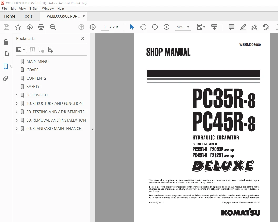
Komatsu PC35R-8 PC45R-8 Hydraulic Excavator Shop Manual WEBD003900 – PDF DOWNLOAD
SERIAL NUMBER
PC35R-8 F20932 and up
PC35R-8 F20932 and up
PC45R-8 F21251 and up
Instant PDF Download
Available immediately
Save to Your Device
Download & keep forever
Antivirus Scanned
100% virus-free
Trusted Worldwide
175,000+ customers
Description
Komatsu PC35R-8 PC45R-8 Hydraulic Excavator Shop Manual WEBD003900 – PDF DOWNLOAD
FILE DETAILS:
Komatsu PC35R-8 PC45R-8 Hydraulic Excavator Shop Manual WEBD003900 – PDF DOWNLOAD
Language : English
Pages : 286
Downloadable : Yes
File Type : PDF
TABLE OF CONTENTS:
Komatsu PC35R-8 PC45R-8 Hydraulic Excavator Shop Manual WEBD003900 – PDF DOWNLOAD
SERIAL NUMBER
PC35R-8 F20932 and up
PC35R-8 F20932 and up
PC45R-8 F21251 and up
MAIN MENU 0
COVER 1
CONTENTS 3
SAFETY 7
FOREWORD 9
HOW TO READ THE SHOP MANUAL 10
HOISTING INSTRUCTIONS 11
STANDARD TIGHTENING TORQUE 12
COATING MATERIALS 14
ELECTRIC WIRE CODE 15
WEIGHT TABLE 16
TABLE OF OIL AND COOLANT QUANTITIES 17
10 STRUCTURE AND FUNCTION 21
P T O 22
POWER TRAIN 23
SWING CIRCLE 24
SWING MACHINERY 25
FINAL DRIVE 26
TRACK FRAME 27
RECOIL SPRING 28
CARRIER ROLLER 29
TRACK ROLLER 29
STEEL SHOE 30
HYDRAULIC CIRCUIT DIAGRAM PC35R-8 31
HYDRAULIC CIRCUIT DIAGRAM PC45R-8 33
HYDRAULIC PUMP 35
CONTROL VALVE 42
CLSS 50
SWIVEL JOINT 72
SWING MOTOR 74
TRAVEL MOTOR 76
CYLINDERS 81
ACCUMULATOR 85
PPC VALVES (WORK EQUIPMENT) 86
PPC VALVE (HAMMER) 90
SOLENOID VALVE 93
ELECTRICAL DIAGRAM (1/3) 95
ELECTRICAL DIAGRAM (2/3) 97
ELECTRICAL DIAGRAM (3/3) 99
20 TESTING AND ADJUSTMENTS 103
NORMAL OR STANDARD TECHNICAL DATA 104
SPECIAL TOOLS 126
CHECKING THE ENGINE SPEED 127
ADJUSTMENT OF VALVE CLEARANCE 128
MEASUREMENT OF THE COMPRESSION PRESSURE 129
CONTROL AND ADJUSTMENT OF THE TENSION OF THE FAN BELT 130
CONTROL AND ADJUSTMENT OF THE INJECTION TIMING 131
CONTROL AND ADJUSTMENT OF THE ACCELERATOR STROKE 133
ADJUSTMENT OF THE STROKE OF THE BLADE COMMAND LEVER 134
ADJUSTING THE FLEXIBLE CABLES 135
CONTROL AND ADJUSTMENT OF THE STROKE OF THE TRAVEL LEVER 136
ADJUSTMENT OF THE STROKE OF THE BOOM SWING COMMAND PEDAL 137
ADJUSTMENT OF THE PPC VALVE CLEARANCES 138
ADJUSTMENT OF THE RUBBER PAD AND SAFETY MICROSWITCH FOR SERVOCONTROL ENGAGEMENT 139
CONTROL AND ADJUSTMENT OF THE TRACK-SHOE TENSION 140
CONTROL AND REGULATION OF THE PRESSURES IN THE HYDRAULIC CIRCUITS 141
CONTROL AND REGULATION OF THE LS DIFFERENTIAL PRESSURE AND ADJUSTMENT OF THE LS VALVE 144
REGULATION OF THE PC VALVE 146
CONTROL AND REGULATION OF THE SERVOCONTROL POWER SUPPLY 147
ELIMINATION OF RESIDUAL PRESSURES – PRESSURISATION OF THE TANK 148
BLEEDING AIR FROM THE HYDRAULIC CIRCUITS 149
CONTROL OF HYDRAULIC DRIFTS – ANALYSIS OF THE CAUSE OF A DRIFT 151
CHECKING FOR ANY LEAKAGES INSIDE THE WORKING EQUIPMENT CYLINDERS 157
CHECKING FOR ANY LEAKAGES INSIDE THE SWING MOTOR 158
METHODS FOR TESTING FOR LEAKAGES INSIDE THE SWIVEL JOINT 159
30 REMOVAL AND INSTALLATION 163
HOW TO READ THE MANUAL 165
PRECAUTIONS TO BE TAKEN WHILE WORKING 166
SPECIAL TOOLS 167
STARTER MOTOR 169
REMOVAL 169
INSTALLATION 169
ALTERNATOR 170
REMOVAL 170
INSTALLATION 170
INJECTION PUMP 171
REMOVAL 171
INSTALLATION 172
NOZZLE HOLDER 173
REMOVAL 173
INSTALLATION 173
WATER COOLANT PUMP 174
REMOVAL 174
INSTALLATION 175
CYLINDER HEAD 176
REMOVAL 176
INSTALLATION 178
RADIATOR GROUP – OIL COOLER 179
REMOVAL 179
INSTALLATION 180
ENGINE HOOD 181
REMOVAL 181
INSTALLATION 181
CANOPY 182
REMOVAL 182
INSTALLATION 182
CAB 183
REMOVAL 183
INSTALLATION 183
HEATING FAN 184
REMOVAL 184
INSTALLATION 185
COUNTERWEIGHT 186
REMOVAL 186
INSTALLATION 186
FUEL TANK 187
REMOVAL 187
INSTALLATION 188
HYDRAULIC TANK 189
REMOVAL 189
INSTALLATION 190
ENGINE-PUMP GROUP 191
REMOVAL 191
INSTALLATION 194
PUMP 195
REMOVAL 195
INSTALLATION 195
ENGINE-PUMP COUPLING 196
REMOVAL 196
INSTALLATION 196
CONTROL VALVE 197
REMOVAL 197
INSTALLATION 198
LEFT-HAND PPC VALVE (ARM-BUCKET) 199
REMOVAL 199
INSTALLATION 199
RIGHT-HAND PPC VALVE (BOOM-BUCKET) 200
REMOVAL 200
INSTALLATION 200
SERVOCONTROL SOLENOID GROUP 201
REMOVAL 201
INSTALLATION 201
PLATFORM 202
REMOVAL 202
INSTALLATION 205
SWIVEL JOINT 206
REMOVAL 206
INSTALLATION 207
SWING MACHINERY 208
REMOVAL 208
INSTALLATION 208
REVOLVING FRAME 209
REMOVAL 209
INSTALLATION 210
SWING CIRCLE 211
REMOVAL 211
INSTALLATION 211
RUBBER TRACK SHOES 212
REMOVAL 212
INSTALLATION 212
STEEL TRACK SHOES 213
REMOVAL 213
INSTALLATION 213
SPROCKET WHEEL 214
REMOVAL 214
INSTALLATION 214
FINAL DRIVE 215
REMOVAL 215
INSTALLATION 215
IDLER AND RECOIL SPRING 216
REMOVAL 216
INSTALLATION 216
SPRING RECOIL AND THRUST CYLINDER GROUPS 217
DISASSEMBLY 217
ASSEMBLY 218
IDLER 220
DISASSEMBLY 220
ASSEMBLY 221
TRACK ROLLERS 222
REMOVAL 222
INSTALLATION 222
BOOM CYLINDER 223
REMOVAL 223
INSTALLATION 224
ARM CYLINDER 225
REMOVAL 225
INSTALLATION 225
BUCKET CYLINDER 226
REMOVAL 226
INSTALLATION 226
BOOM SWING CYLINDER 227
REMOVAL 227
INSTALLATION 228
BLADE CYLINDER 229
REMOVAL 229
INSTALLATION 229
WORK EQUIPMENT CYLINDERS 230
DISASSEMBLY 230
ASSEMBLY 232
UPPER WORK EQUIPMENT 236
REMOVAL 236
INSTALLATION 237
BUCKET 238
REMOVAL 238
INSTALLATION 238
ARM 239
REMOVAL 239
INSTALLATION 240
ARM ASSEMBLY 241
REMOVAL 241
INSTALLATION 241
BOOM 242
REMOVAL 242
INSTALLATION 243
BOOM SWING SUPPORT 244
REMOVAL 244
INSTALLATION 244
BLADE 245
REMOVAL 245
INSTALLATION 245
40 STANDARD MAINTENANCE 249
SWING CIRCLE 250
SWING MACHINERY 251
FINAL DRIVE 252
SPROCKET 253
IDLER 254
STEEL SHOE 255
PC35R 255
PC45R 256
CARRIER ROLLER 257
TRACK ROLLER 258
RUBBER SHOE 259
TRACK FRAME 260
HYDRAULIC PUMP 262
CONTROL VALVE 263
SWIVEL JOINT 269
SWING MOTOR 270
TRAVEL MOTOR 272
PC35R 272
PC45R 274
PPC VALVE (FOR BOOM, ARM, BUCKET, SWING) 276
PPC VALVE (FOR HAMMER) 277
CYLINDERS 278
PC35R 278
PC45R 280
WORK EQUIPMENT 282
PC35R-8 282
PC45R 284
COVER 1
CONTENTS 3
SAFETY 7
FOREWORD 9
HOW TO READ THE SHOP MANUAL 10
HOISTING INSTRUCTIONS 11
STANDARD TIGHTENING TORQUE 12
COATING MATERIALS 14
ELECTRIC WIRE CODE 15
WEIGHT TABLE 16
TABLE OF OIL AND COOLANT QUANTITIES 17
10 STRUCTURE AND FUNCTION 21
P T O 22
POWER TRAIN 23
SWING CIRCLE 24
SWING MACHINERY 25
FINAL DRIVE 26
TRACK FRAME 27
RECOIL SPRING 28
CARRIER ROLLER 29
TRACK ROLLER 29
STEEL SHOE 30
HYDRAULIC CIRCUIT DIAGRAM PC35R-8 31
HYDRAULIC CIRCUIT DIAGRAM PC45R-8 33
HYDRAULIC PUMP 35
CONTROL VALVE 42
CLSS 50
SWIVEL JOINT 72
SWING MOTOR 74
TRAVEL MOTOR 76
CYLINDERS 81
ACCUMULATOR 85
PPC VALVES (WORK EQUIPMENT) 86
PPC VALVE (HAMMER) 90
SOLENOID VALVE 93
ELECTRICAL DIAGRAM (1/3) 95
ELECTRICAL DIAGRAM (2/3) 97
ELECTRICAL DIAGRAM (3/3) 99
20 TESTING AND ADJUSTMENTS 103
NORMAL OR STANDARD TECHNICAL DATA 104
SPECIAL TOOLS 126
CHECKING THE ENGINE SPEED 127
ADJUSTMENT OF VALVE CLEARANCE 128
MEASUREMENT OF THE COMPRESSION PRESSURE 129
CONTROL AND ADJUSTMENT OF THE TENSION OF THE FAN BELT 130
CONTROL AND ADJUSTMENT OF THE INJECTION TIMING 131
CONTROL AND ADJUSTMENT OF THE ACCELERATOR STROKE 133
ADJUSTMENT OF THE STROKE OF THE BLADE COMMAND LEVER 134
ADJUSTING THE FLEXIBLE CABLES 135
CONTROL AND ADJUSTMENT OF THE STROKE OF THE TRAVEL LEVER 136
ADJUSTMENT OF THE STROKE OF THE BOOM SWING COMMAND PEDAL 137
ADJUSTMENT OF THE PPC VALVE CLEARANCES 138
ADJUSTMENT OF THE RUBBER PAD AND SAFETY MICROSWITCH FOR SERVOCONTROL ENGAGEMENT 139
CONTROL AND ADJUSTMENT OF THE TRACK-SHOE TENSION 140
CONTROL AND REGULATION OF THE PRESSURES IN THE HYDRAULIC CIRCUITS 141
CONTROL AND REGULATION OF THE LS DIFFERENTIAL PRESSURE AND ADJUSTMENT OF THE LS VALVE 144
REGULATION OF THE PC VALVE 146
CONTROL AND REGULATION OF THE SERVOCONTROL POWER SUPPLY 147
ELIMINATION OF RESIDUAL PRESSURES – PRESSURISATION OF THE TANK 148
BLEEDING AIR FROM THE HYDRAULIC CIRCUITS 149
CONTROL OF HYDRAULIC DRIFTS – ANALYSIS OF THE CAUSE OF A DRIFT 151
CHECKING FOR ANY LEAKAGES INSIDE THE WORKING EQUIPMENT CYLINDERS 157
CHECKING FOR ANY LEAKAGES INSIDE THE SWING MOTOR 158
METHODS FOR TESTING FOR LEAKAGES INSIDE THE SWIVEL JOINT 159
30 REMOVAL AND INSTALLATION 163
HOW TO READ THE MANUAL 165
PRECAUTIONS TO BE TAKEN WHILE WORKING 166
SPECIAL TOOLS 167
STARTER MOTOR 169
REMOVAL 169
INSTALLATION 169
ALTERNATOR 170
REMOVAL 170
INSTALLATION 170
INJECTION PUMP 171
REMOVAL 171
INSTALLATION 172
NOZZLE HOLDER 173
REMOVAL 173
INSTALLATION 173
WATER COOLANT PUMP 174
REMOVAL 174
INSTALLATION 175
CYLINDER HEAD 176
REMOVAL 176
INSTALLATION 178
RADIATOR GROUP – OIL COOLER 179
REMOVAL 179
INSTALLATION 180
ENGINE HOOD 181
REMOVAL 181
INSTALLATION 181
CANOPY 182
REMOVAL 182
INSTALLATION 182
CAB 183
REMOVAL 183
INSTALLATION 183
HEATING FAN 184
REMOVAL 184
INSTALLATION 185
COUNTERWEIGHT 186
REMOVAL 186
INSTALLATION 186
FUEL TANK 187
REMOVAL 187
INSTALLATION 188
HYDRAULIC TANK 189
REMOVAL 189
INSTALLATION 190
ENGINE-PUMP GROUP 191
REMOVAL 191
INSTALLATION 194
PUMP 195
REMOVAL 195
INSTALLATION 195
ENGINE-PUMP COUPLING 196
REMOVAL 196
INSTALLATION 196
CONTROL VALVE 197
REMOVAL 197
INSTALLATION 198
LEFT-HAND PPC VALVE (ARM-BUCKET) 199
REMOVAL 199
INSTALLATION 199
RIGHT-HAND PPC VALVE (BOOM-BUCKET) 200
REMOVAL 200
INSTALLATION 200
SERVOCONTROL SOLENOID GROUP 201
REMOVAL 201
INSTALLATION 201
PLATFORM 202
REMOVAL 202
INSTALLATION 205
SWIVEL JOINT 206
REMOVAL 206
INSTALLATION 207
SWING MACHINERY 208
REMOVAL 208
INSTALLATION 208
REVOLVING FRAME 209
REMOVAL 209
INSTALLATION 210
SWING CIRCLE 211
REMOVAL 211
INSTALLATION 211
RUBBER TRACK SHOES 212
REMOVAL 212
INSTALLATION 212
STEEL TRACK SHOES 213
REMOVAL 213
INSTALLATION 213
SPROCKET WHEEL 214
REMOVAL 214
INSTALLATION 214
FINAL DRIVE 215
REMOVAL 215
INSTALLATION 215
IDLER AND RECOIL SPRING 216
REMOVAL 216
INSTALLATION 216
SPRING RECOIL AND THRUST CYLINDER GROUPS 217
DISASSEMBLY 217
ASSEMBLY 218
IDLER 220
DISASSEMBLY 220
ASSEMBLY 221
TRACK ROLLERS 222
REMOVAL 222
INSTALLATION 222
BOOM CYLINDER 223
REMOVAL 223
INSTALLATION 224
ARM CYLINDER 225
REMOVAL 225
INSTALLATION 225
BUCKET CYLINDER 226
REMOVAL 226
INSTALLATION 226
BOOM SWING CYLINDER 227
REMOVAL 227
INSTALLATION 228
BLADE CYLINDER 229
REMOVAL 229
INSTALLATION 229
WORK EQUIPMENT CYLINDERS 230
DISASSEMBLY 230
ASSEMBLY 232
UPPER WORK EQUIPMENT 236
REMOVAL 236
INSTALLATION 237
BUCKET 238
REMOVAL 238
INSTALLATION 238
ARM 239
REMOVAL 239
INSTALLATION 240
ARM ASSEMBLY 241
REMOVAL 241
INSTALLATION 241
BOOM 242
REMOVAL 242
INSTALLATION 243
BOOM SWING SUPPORT 244
REMOVAL 244
INSTALLATION 244
BLADE 245
REMOVAL 245
INSTALLATION 245
40 STANDARD MAINTENANCE 249
SWING CIRCLE 250
SWING MACHINERY 251
FINAL DRIVE 252
SPROCKET 253
IDLER 254
STEEL SHOE 255
PC35R 255
PC45R 256
CARRIER ROLLER 257
TRACK ROLLER 258
RUBBER SHOE 259
TRACK FRAME 260
HYDRAULIC PUMP 262
CONTROL VALVE 263
SWIVEL JOINT 269
SWING MOTOR 270
TRAVEL MOTOR 272
PC35R 272
PC45R 274
PPC VALVE (FOR BOOM, ARM, BUCKET, SWING) 276
PPC VALVE (FOR HAMMER) 277
CYLINDERS 278
PC35R 278
PC45R 280
WORK EQUIPMENT 282
PC35R-8 282
PC45R 284
DESCRIPTION:
Komatsu PC35R-8 PC45R-8 Hydraulic Excavator Shop Manual WEBD003900 – PDF DOWNLOAD
SERIAL NUMBER
PC35R-8 F20932 and up
PC35R-8 F20932 and up
PC45R-8 F21251 and up
GENERAL PRECAUTIONS :
Mistakes in operation are extremely dangerous. Read the OPERATION & MAINTENANCE MANUAL carefully BEFORE operating the machine.
1. Before carrying out any greasing or repairs, read all the precautions given on the decals which are fixed to the machine.
2. When carrying out any operation, always wear safety shoes and helmet. Do not wear loose work clothes, or clothes with buttons missing.
● Always wear safety glasses when hitting parts with a hammer.
● Always wear safety glasses when grinding parts with a grinder, etc.
3. If welding repairs are needed, always have a trained, experienced welder carry out the work. When carrying out welding work, always wear welding gloves, apron, glasses, cap and other clothes suited for welding work.
4. When carrying out any operation with two or more workers, always agree on the operating procedure before starting. Always inform your fellow workers before starting any step of the operation. Before starting work, hang UNDER REPAIR signs on the controls in the operator’s compartment.
5. Keep all tools in good condition and learn the correct way to use them.
6. Decide a place in the repair workshop to keep tools and removed parts. Always keep the tools and parts in their correct places. Always keep the work area clean and make sure that there is no dirt or oil on the floor. Smoke only in the areas provided for smoking. Never smoke while working.
PREPARATIONS FOR WORK:
7. Before adding oil or making repairs, park the machine on hard, level ground, and block the wheels or tracks to prevent the machine from moving.
8. Before starting work, lower blade, ripper, bucket or any other work equipment to the ground. If this is not possible, insert the safety pin or use blocks to prevent the work equipment from falling. In addition, be sure to lock all the control levers and hang warning signs on them.
9. When disassembling or assembling, support the machine with blocks, jacks or stands before starting work.
10. Remove all mud and oil from the steps or other places used to get on and off the machine. Always use the handrails, ladders or steps when getting on or off the machine. Never jump on or off the machine. If it is impossible to use the handrails, ladders or steps, use a stand to provide safe footing.
PRECAUTIONS DURING WORK :
11. When removing the oil filler cap, drain plug or hydraulic pressure measuring plugs, loosen them slowly to prevent the oil from spurting out. Before disconnecting or removing components of the oil, water or air circuits, first remove the pressure completely from the circuit.
12. The water and oil in the circuits are hot when the engine is stopped, so be careful not to get burned. Wait for the oil and water to cool before carrying out any work on the oil or water circuits.
13. Before starting work, remove the leads from the battery. ALWAYS remove the lead from the negative (-) terminal first.
IMAGES PREVIEW OF THE MANUAL:
S.V 20/12/24



