
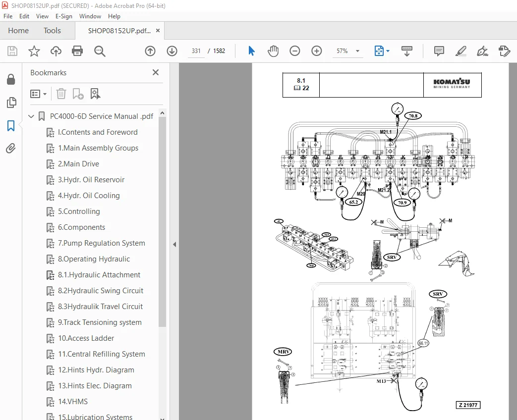
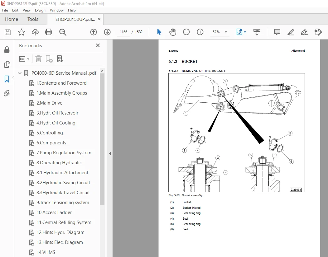
Komatsu PC4000-6 Diesel Hydraulic Excavator Shop Manual PDF
$36.95
Komatsu PC4000-6 Diesel Hydraulic Excavator Shop Manual – PDF DOWNLOAD
Description
Komatsu PC4000-6 Diesel Hydraulic Excavator Shop Manual – PDF DOWNLOAD
FILE DETAILS:
Komatsu PC4000-6 Diesel Hydraulic Excavator Shop Manual – PDF DOWNLOAD
Language : English
Pages : 1582
Downloadable : Yes
File Type : PDF
IMAGES PREVIEW OF THE MANUAL:
DESCRIPTION:
Komatsu PC4000-6 Diesel Hydraulic Excavator Shop Manual – PDF DOWNLOAD
GENERAL PRECAUTIONS:
Mistakes in operation are extremely dangerous. Read the OPERATION & MAINTENANCE
MANUAL carefully BEFORE operating the machine.
1. Before carrying out any greasing or repairs, read all the precautions given on the decals
which are fixed to the machine.
2. When carrying out any operation, always wear safety shoes and helmet. Do not wear
loose work clothes, or clothes with buttons missing.
• Always wear safety glasses when hitting parts with a hammer.
• Always wear safety glasses when grinding parts with a grinder, etc.
3. If welding repairs are needed, always have a trained, experienced welder carry out the
work. When carrying out welding work, always wear welding gloves, apron, glasses, cap
and other clothes suited for welding work.
4. When carrying out any operation with two or more workers, always agree on the
operating procedure before starting. Always inform your fellow workers before starting
any step of the operation. Before starting work, hang UNDER REPAIR signs on the
controls in the operator’s compartment.
5. Keep all tools in good condition and learn the correct way to use them.
6. Decide a place in the repair workshop to keep tools and removed parts. Always keep the
tools and parts in their correct places. Always keep the work area clean and make sure
that there is no dirt or oil on the floor. Smoke only in the areas provided for smoking.
Never smoke while working.
PREPARATIONS FOR WORK
7. Before adding oil or making repairs, park the machine on hard, level ground, and block
the wheels or tracks to prevent the machine from moving.
8. Before starting work, lower bucket, hammer or any other work equipment to the ground.
If this is not. possible, insert the safety pin or use blocks to prevent the work equipment
from falling. In addition, be sure to lock all the control levers and hang warning signs on
them.
9. When disassembling or assembling, support the machine with blocks, jacks or stands
before starting work.
10. Remove all mud and oil from the steps or other places used to get on and off the machine.
Always use the handrails, ladders or steps when getting on or off the machine. Never
jump on or off the machine. If it is impossible to use the handrails, ladders or steps, use a
stand to provide safe footing.
TABLE OF CONTENTS:
Komatsu PC4000-6 Diesel Hydraulic Excavator Shop Manual – PDF DOWNLOAD
PC4000-6D Service Manual pdf 0
I Contents and Foreword 20
1 Main Assembly Groups 22
2 Main Drive 51
3 Hydr Oil Reservoir 80
4 Hydr Oil Cooling 97
5 Controlling 112
6 Components 157
7 Pump Regulation System 200
8 Operating Hydraulic 285
8 1 Hydraulic Attachment 290
8 2Hydraulic Swing Circuit 410
8 3Hydraulik Travel Circuit 387
9 Track Tensioning system 455
10 Access Ladder 441
11 Central Refilling System 450
12 Hints Hydr Diagram 472
13 Hints Elec Diagram 484
14 VHMS 552
15 Lubrication Systems 648
PC4000-6 Disassembly and Assembly 0
1 Introduction 759
1 1 Contents of the binder 760
1 2 Foreword 761
1 2 1 Service 762
2 Safety 763
2 1 Safety Instructions 764
2 1 1 Method of using this manual 764
2 1 2 General precautions 766
2 1 3 Preparations for work 767
2 1 4 Precautions during work 768
2 1 5 WARNING OF SPECIAL DANGERS 770
2 1 5 1 ELECTRICal ENERGY 770
2 1 5 2 GAS, DUST, STEAM AND SMOKE 771
2 1 5 3 HYDRAULIC, AIR CONDITIONING AND PNEUMATIC EQUIPMENT 772
2 1 5 4 NOISE 772
2 1 5 5 Heat 773
2 1 5 6 OIL, GREASE AND OTHER CHEMICAL SUBSTANCES 773
2 1 5 7 Height 773
2 1 6 SPECIAL SAFETY EQUIPMENT 775
2 1 6 1 SAFETY HARNESS IN CONFORMITY WITH EN 361 (EUROPEAN STANDARD) 775
2 1 6 2 INSTRUCTIONS FOR USE 777
2 1 6 3 RECOMMENDATIONS FOR USE OF THE HOLDING HOOKS AND HOLD-BACK HOOKS OF THE SAFETY HARNESS 779
2 1 6 4 INSTRUCTIONS FOR USE 781
2 2 Lifting Gears 782
2 2 1 Wire ropes 782
2 2 2 Sling accessory 784
2 2 3 Weight tables 785
2 2 3 1 Superstructure 785
2 2 3 2 Undercarriage 787
2 2 3 3 Backhoe AttachmenT (BHA) 788
2 2 3 4 Faceshovel Attachment (FSA) 789
2 3 Torque charts according to DIN 791
2 3 1 Metric standard thread 791
2 3 2 Metric fine thread 792
2 3 3 Cummins motor torques – metric 793
2 3 4 Cummins motor torques – U S Customary 793
2 3 5 Flange connections 794
2 4 Conversation table 795
2 4 1 Method of using the conversation table 795
2 4 2 Millimeter – Inch & Kilogram – Pound 796
2 4 3 Liter – U S Gallon & Liter – U K Gallon 797
2 4 4 KGm – ft lb 798
2 4 5 bar – PSI / PSI – bar 799
2 4 6 Basic Values in Ohm according to DIN 43 76 800
2 4 7 Temperature 801
2 5 Explanation of abbreviations 802
3 Superstructure 803
3 1 Diesel Engine 804
3 1 1 Removal of the Diesel engine 804
3 1 2 Replacement of the Diesel engine 811
3 1 3 Engine torque support and engine/PTO mounts 814
3 1 3 1 Flexible mounts 815
3 1 3 2 Torque support 817
3 1 4 Alternator 818
3 1 4 1 Removal of the alternator 818
3 1 4 2 Replacement of the alternator 819
3 1 5 Batteries 820
3 1 5 1 Removal of the batteries 820
3 1 5 2 Replacement of the batteries 822
3 1 6 Radiator fan 824
3 1 6 1 Removal of the radiator fan assembly 825
3 1 6 2 Replacement of the radiator fan assembly 829
3 1 6 3 Removal of the radiator fan 831
3 1 6 4 Replacement of the radiator fan 831
3 1 6 5 Removal of the radiator fan drive pump 832
3 1 6 6 Replacement of the radiator fan drive pump 834
3 1 7 Radiators 835
3 1 7 1 Removal of the Radiator assembly 835
3 1 7 2 Replacement of the radiator assembly 839
3 1 8 Fuel cooler 840
3 1 8 1 Removal of the fuel cooler 840
3 1 8 2 Replacement of the fuel cooler 842
3 1 9 Starter system 843
3 1 9 1 Removal of the starter motor 843
3 1 9 2 Replacement of the starter motor 843
3 1 10 Geislinger coupling 844
3 1 10 1 Removal of the Geislinger coupling 845
3 1 10 2 Replacement of the Geislinger coupling 847
3 2 PTO 848
3 2 1 Main pumps 848
3 2 1 1 Preparatory works for main pump removal 849
3 2 1 2 Removal of Main Pump 1 852
3 2 1 3 Replacement of main pump 1 853
3 2 1 4 Removal of Main Pump 2 855
3 2 1 5 Replacement of main pump 2 857
3 2 1 6 Removal of Main Pump 3 859
3 2 1 7 Replacement of main pump 3 861
3 2 1 8 Removal of Main Pump 4 862
3 2 1 9 Replacement of main pump 4 864
3 2 2 PTO oil circulation pump (auxiliary pump) 865
3 2 2 1 Removal of the oil circulation pump (auxiliary pump) 865
3 2 2 2 Replacement of the oil circulation pump (auxiliary pump) 867
3 2 3 Pump distributor gearbox (PTO) 868
3 2 3 1 Removal of the Pump distributor gearbox (PTO) 870
3 2 3 2 Replacement of the Pump distributor gearbox (PTO) 873
3 3 Hydraulics 874
3 3 1 Hydraulic cooler fan Drive Pump 874
3 3 1 1 Removal of the hydraulic cooler fan drive pump 874
3 3 1 2 Replacement of the hydraulic cooler fan drive pump 877
3 3 2 Hydraulic Cooler Fan Assembly 878
3 3 2 1 Removal of hydraulic cooler fan assembly 878
3 3 2 2 Replacement of hydraulic cooler fan assembly 881
3 3 2 3 Removal of hydraulic cooler Fan and motor 882
3 3 2 4 Replacement of hydraulic cooler Fan and motor 884
3 3 3 Hydraulic Oil Coolers 886
3 3 3 1 Removal of the hydraulic oil coolers 888
3 3 3 2 Replacement of the hydraulic oil coolers 892
3 3 3 3 Removal of the hydraulic oil cooler frame 894
3 3 3 4 Replacement of the hydraulic oil cooler frame 899
3 3 4 Main Relief Valves (MRV) 900
3 3 4 1 Removal of the MRV 900
3 3 4 2 Replacement of the MRV 901
3 3 5 pilot oil pump (Gear pump) 902
3 3 5 1 Removal of the pilot oil pump) 902
3 3 5 2 Replacement of the pilot oil pump 904
3 3 6 Main Gate Valve 904
3 3 6 1 Removal of the main gate valve 905
3 3 6 2 Replacement of the main gate valve 906
3 3 7 Hydraulic Oil Reservoir 908
3 3 7 1 Removal of the hydraulic oil reservoir 910
3 3 7 2 Replacement of the hydraulic oil reservoir 917
3 3 8 Main Control Valve Blocks 919
3 3 8 1 Removal of the main control valve blocks 928
3 3 8 2 Replacement of the main control valve blocks 932
3 3 9 Service line Relief Valves (SRV) 933
3 3 9 1 Removal of SRV on main Control valve block 933
3 3 9 2 Replacement of SRV on main control valve blocks 936
3 3 10 Anti-cavitation Valves (ACV) 938
3 3 10 1 Removal of ACV on Manifold 939
3 3 10 2 Replacement of ACV on Manifold 944
3 3 10 3 Removal of ACV on main control valve blocks 945
3 3 10 4 Replacement of ACV on main control valve blocks 947
3 3 11 Throttle check valves 948
3 3 11 1 Removal of throttle check valves 950
3 3 11 2 Replacement of throttle check valves 953
3 3 12 manifold 954
3 3 12 1 Removal of the manifold 954
3 3 12 2 Replacement of the manifold 956
3 3 12 3 Removal of the Diffuser on the Manifold (FSA only) 957
3 3 12 4 Replacement of Diffuser on Manifold (FSA only) 959
3 4 Slew Drive 961
3 4 1 Slew Gear 962
3 4 1 1 Removal of the slew gear 963
3 4 1 2 Replacement of the slew gear 965
3 4 2 Swing Motor 968
3 4 2 1 Removal of the swing motor 969
3 4 2 2 Replacement of the swing motor 972
3 4 3 Slew parking brake 975
3 4 3 1 Removal/Disassembly of the slew parking brake 977
3 4 3 2 Replacement/assembly of the slew parking brake 980
3 4 4 Dynamic Slew Brake 982
3 4 4 1 Removal of the slew brake valve 985
3 4 4 2 Replacement of the slew brake valve 987
3 4 5 Swing circle lubrication pinion (dummy wheel) 988
3 4 5 1 Removal of the lubrication pinion assembly 990
3 4 5 2 Replacement of the lubrication pinion assembly 992
3 5 Lubrication pumps 993
3 5 1 Removal of the Lubrication pump 993
3 5 2 Replacement of the lubricating pump 995
3 6 Pump controller MC7 996
3 6 1 Removal of the pump controller MC7 996
3 6 2 Replacement of the pump controller MC7 997
3 7 Operator’s Cab 998
3 7 1 Removal of the operator’s cab 1001
3 7 2 Replacement of the operator’s cab 1006
3 7 3 Cab-mounts 1007
3 7 3 1 Removal of the cab-mounts 1007
3 7 3 2 replacement of the cab-mounts 1009
3 7 4 FRONT WINDOW 1010
3 7 4 1 Removal of the Front window 1010
3 7 4 2 Replacement of the front window 1011
3 7 5 Operator’s seat 1012
3 7 5 1 Removal of the operator’s seat 1012
3 7 5 2 Replacement of the operator’s seat 1013
3 7 6 VHMS 1014
3 7 6 1 Removal of the VHMS-Controller 1014
3 7 6 2 Replacement of the VHMS-Controller 1015
3 7 7 Access Ladder 1016
3 7 7 1 Removal of the access Ladder 1019
3 7 7 2 Replacement of the access ladder 1021
3 7 7 3 Removal of the access ladder cylinder 1023
3 7 7 4 Replacement of the access ladder cylinder 1025
3 7 8 Removal of the cab base 1026
3 7 9 Replacement of the cab base 1028
3 8 Counterweight 1030
3 8 1 Removal of the counterweight 1031
3 8 2 Replacement of the counterweight 1033
3 9 Superstructure Lifting 1034
3 9 1 Remove the Superstructure from the Undercarriage 1034
3 9 2 Install the Superstructure onto the undercarriage 1037
3 10 Fuel Tank 1040
3 10 1 Removal of the Fuel tank 1041
3 10 2 Replacement of the Fuel tank 1044
4 Undercarriage 1047
4 1 Travel System 1048
4 1 1 Track group 1048
4 1 1 1 Changing of the track group 1048
4 1 2 Sprocket 1052
4 1 2 1 Removal of the sprocket 1052
4 1 2 2 Replacement of the sprocket 1056
4 1 3 Guide wheels 1058
4 1 3 1 Removal of the guide wheel assembly 1058
4 1 3 2 Replacement of the guide wheel assembly 1059
4 1 4 Track tensioning accumulators 1060
4 1 4 1 Removal of the low pressure accumulators 1060
4 1 4 2 Replacement of the low pressure accumulators 1062
4 1 4 3 Removal of the high pressure accumulators 1063
4 1 4 4 Replacement of the high pressure accumulators 1064
4 1 5 Track tension valve block 1065
4 1 5 1 Removal of the track tensioning valve block 1065
4 1 5 2 Replacement of the track tensioning valve block 1066
4 1 6 Hydraulic hoses of the track tensioning system 1067
4 1 6 1 Substitute the hydraulic hoses 1067
4 1 7 Travel brake valve block (overspeed valve) 1070
4 1 7 1 Removal of the travel brake valve block 1071
4 1 7 2 Replacement of the travel brake valve block 1073
4 1 8 Track tensioning cylinders 1074
4 1 8 1 Removal of the track tensioning cylinders 1074
4 1 8 2 Replacement of the track tensioning cylinders 1075
4 1 9 Travel motor 1076
4 1 9 1 Removal of the travel motors 1076
4 1 9 2 Replacement of the travel motors 1078
4 1 10 travel parking brake 1080
4 1 10 1 Removal/disassembly of the travel parking brake 1083
4 1 10 2 Replacement/assembly of the travel parking brake 1086
4 1 11 Travel gearbox 1088
4 1 11 1 Removal of the travel gearbox 1089
4 1 11 2 Replacement of the travel gearbox 1091
4 1 12 Carrier roller 1092
4 1 12 1 Removal of the carrier roller assembly 1092
4 1 12 2 Replacement of the carrier roller assembly 1094
4 1 13 Track roller 1095
4 1 13 1 Removal of the Track roller assembly 1095
4 1 13 2 Replacement of the Track roller assembly 1097
4 2 Car body 1098
4 2 1 Removal of the car bodY (previous type with mounting pins) 1098
4 2 2 Replacement of the car bodY (previous type with mounting pins) 1102
4 2 3 Removal OF the car Body (NEW type with bolted connection) 1106
4 2 4 Replacement of the car body (NEW type with bolted connection) 1111
4 2 4 1 Tightening torque for the crawler carrier mounting bolts 1116
4 2 5 Rotary joint 1120
4 2 5 1 Removal of the rotary joint 1122
4 2 5 2 Replacement of the rotary joint 1125
4 2 6 swing circle 1126
4 2 6 1 Removal of the swing circle 1128
4 2 6 2 Replacement of the swing circle 1130
5 Attachment 1135
5 1 Backhoe 1136
5 1 1 Boom 1138
5 1 1 1 Removal of the Boom 1138
5 1 1 2 Replacement of the boom 1142
5 1 1 3 Removal of boom cylinders 1144
5 1 1 4 Replacement of boom cylinders 1149
5 1 2 Stick 1152
5 1 2 1 Removal of the Stick 1152
5 1 2 2 Replacement of Stick 1156
5 1 2 3 Removal of Stick Cylinders 1158
5 1 2 4 Replacement of Stick cylinders 1163
5 1 3 Bucket 1166
5 1 3 1 Removal of the bucket 1166
5 1 3 2 Replacement of the bucket 1169
5 1 3 3 Removal of Bucket Cylinders 1170
5 1 3 4 Replacement of Bucket Cylinders 1175
5 1 4 Bucket link rod and steering rods 1177
5 1 4 1 Removal of the bucket link rod 1177
5 1 4 2 Replacement of the bucket link rod 1179
5 1 4 3 Removal of the steering rods 1180
5 1 4 4 Replacement of the steering rods 1183
5 1 5 Ground engaging tools (GET) 1184
5 1 5 1 Removal and replacement of the GET 1184
5 1 6 Hydraulic hoses at the backhoe attachment 1186
5 1 6 1 Substitute the boom arc hoses 1186
5 1 6 2 Substitute the boom cylinder hoses 1190
5 1 6 3 Substitute the stick cylinder hoses 1194
5 1 6 4 Substitute the bucket cylinder hoses 1198
5 2 Faceshovel 1203
5 2 1 Boom 1204
5 2 1 1 Removal of the boom 1204
5 2 1 2 Replacement of the boom 1209
5 2 1 3 Removal of the boom cylinders 1214
5 2 1 4 Replacement of the boom cylinders 1219
5 2 2 Stick 1222
5 2 2 1 Removal of the stick 1222
5 2 2 2 Replacement of the stick 1226
5 2 2 3 Removal of the stick cylinders 1228
5 2 2 4 Replacement of the stick cylinders 1233
5 2 3 Bullclam bucket 1236
5 2 3 1 Removal of the bull clam bucket 1236
5 2 3 2 Replacement of the bull clam bucket 1242
5 2 3 3 Removal of the bucket cylinders 1244
5 2 3 4 Replacement of the bucket cylinders 1248
5 2 3 5 Removal of the clam cylinders 1252
5 2 3 6 Replacement of the clam cylinders 1256
5 2 4 Ground engaging tools (GET) 1258
5 2 4 1 Removal and replacement of the GET 1258
5 2 5 Hydraulic hoses at the Faceshovel attachment 1260
5 2 5 1 Substitute the boom arc hoses 1260
5 2 5 2 Substitute the boom cylinder hoses 1264
5 2 5 3 Substitute the stick arc hoses 1268
5 2 5 4 Substitute the stick cylinder hoses 1272
5 2 5 5 Substitute the bucket cylinder hoses 1276
5 2 5 6 Substitute the clam cylinder hoses 1280
5 3 Metering valves (grease injectors) at the attachment 1288
5 3 1 Removal of the metering valves (grease injectors) 1288
5 3 2 Replacement of the metering valves (grease injectors) 1289
5 4 Cylinder bypass test 1290
6 Appendix 1293
6 1 Fuel and Lubricants 1294
6 2 Filling Capacities 1296
6 3 Tools List 1298
6 3 1 Used special tools (Overview) 1298
6 3 2 KOMATSU tools catalogue 1301
6 4 Work instructions 1348
6 4 1 Remove / install the crawler carrier 1348
6 4 2 Use of the hydraulic torque wrench (supplier’s documentation) 1349
6 5 Service Bulletins 1377
6 5 1 AH00511d 1379
6 5 2 AH00514 1401
6 5 3 AH00519 1415
6 5 4 AH01512 1421
6 5 5 AH01521a 1431
6 5 6 AH01531A 1443
6 5 7 AH02513b 1455
6 5 8 AH02521 1461
6 5 9 AH03506B 1469
6 5 10 AH03509a 1477
6 5 11 AH03510 1505
6 5 12 AH03526a 1525
6 5 13 AH03538 1529
6 5 14 AH04518 1557
6 5 15 AH05510 1561
6 5 16 AH05511 1565
6 5 17 AH05546 1571
6 5 18 AH06524 1575
6 5 19 AH06530 1579
S.V 11/12/24



