
Komatsu PC4000E-6 Hydraulic Mining Shovel Shop Manual 08165E-GB-2 – PDF DOWNLOAD
Original price was: $89.95.$36.95Current price is: $36.95.
Komatsu PC4000E-6 Hydraulic Mining Shovel Shop Manual 08165E-GB-2 – PDF DOWNLOAD
Description
Komatsu PC4000E-6 Hydraulic Mining Shovel Shop Manual 08165E-GB-2 – PDF DOWNLOAD
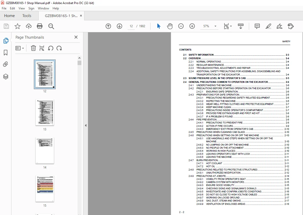
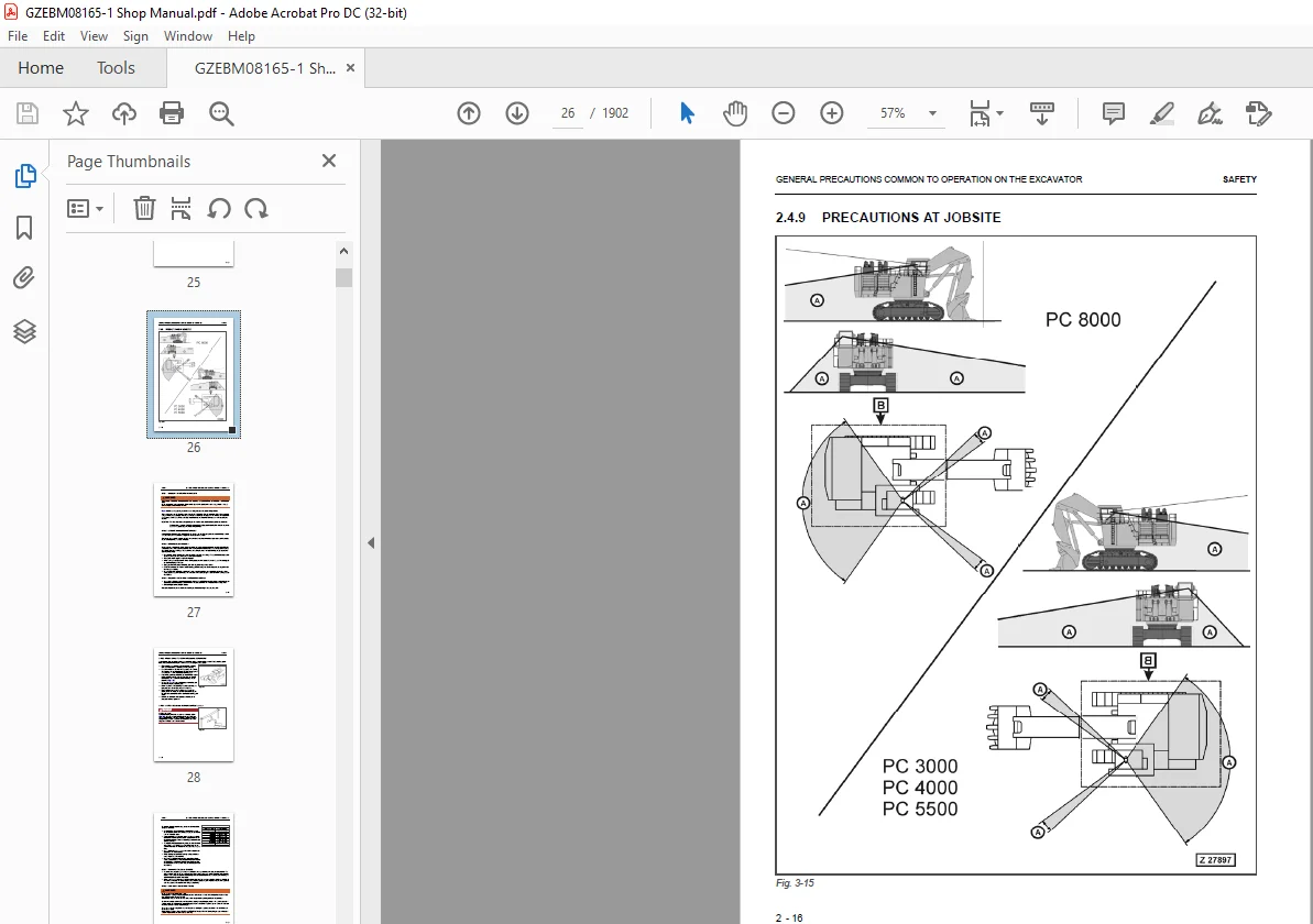
IMAGES PREVIEW OF THE MANUAL:
Need help? Contact: [email protected]
https://vimeo.com/743333480
TABLE OF CONTENTS:
Komatsu PC4000E-6 Hydraulic Mining Shovel Shop Manual 08165E-GB-2 – PDF DOWNLOAD
00 Foreword 4
Introduction 6
Safety Instructions 11
01 Specification 32
Specification PC4000 34
10 Structure, Function 42
I INTRODUCTION 44
I I Contents of the Binder 64
I II Foreword 65
1 2 1 Importand Note 67
I III Explanation of Abbrevations 69
II SAFETY 11
III SPECIFICATIONS 50
III I Lifting Gears 108
III II Standard Tightening Torque Chart 110
III III Conversion Table 111
III IV General Specifications 118
1 MAIN ASSEMBLY GROUPS 61
1 1 General Layout 78
1 2 Superstructure 80
1 3 Machine House 82
1 4 Hydraulic Oil Reservoir 84
1 5 Hydraulic Oil Cooler 86
1 6 Fuel Tank 88
1 7 Counterweight 90
1 8 Cab Support 92
1 9 Operator’s Cab 94
1 10 Control Blocks 96
1 11 Swing Gears 98
1 12 Undercarriage 100
1 13 Backhoe Attachment (BHA) 102
1 14 Front Shovel Attachment (FSA) 104
2 DRIVE 91
2 1 Prime Drive Assembly 120
2 2 Engine and PTO Mounts 122
2 2 1 Flexible Mounts 123
2 2 2 Torque Support 125
2 3 Fan Drive and Radiator Assembly 126
2 3 1 Radiator Fan Drive Speed Adjustment 130
2 4 Pump Distributor Gearbox (PTO) 134
2 4 1 Spline Shaft Housing 136
2 4 2 PTO Lubrication and Cooling 138
2 4 3 Hydraulic Pumps – Location, Drive Speed and Flow Rates 144
2 5 Geislinger Coupling 146
2 6 Air Filter 148
3 HYDRAULIC OIL TANK 107
3 1 General Layout 152
3 2 Main Oil Tank, Location of Electric Equipment 154
3 3 Suction Oil Reservoir with Strainers 156
3 4 Return Oil Collector Tube with Strainer 158
3 5 Back Pressure Valve 160
3 6 Transfer Pump 162
3 6 1 Evacuation of the suction oil reservoir 165
3 6 2 Evacuation of the return oil collector pipes and cooler circuit 167
3 7 Return and Leak Oil Filter 168
3 8 Breather Filter 170
4 HYDRAULIC OIL COOLING 135
4 1 General 174
4 2 Function of the Hydraulic Oil Cooling Circuit 176
4 3 Adjustment of the Back Pressure Valve 178
4 4 Fan Drive (Two Stage Cooler Fan RPM Control) 180
4 4 1 Fixed Displacement Pump, with Variable Setting 182
4 4 2 Pressure Relief Valves 184
4 4 3 fan speed control valve arrangement 186
4 5 Adjustment of the Cooler Fan Drive Speed 188
4 5 1 Function Check of Fan Speed Control 193
5 CONTROLLING 157
5 1 General Layout 196
5 2 Control and Filter Panel Location of Components 198
5 3 Pilot Pressure Supply and Adjustments 204
5 3 1 Pilot Pressure Circuit (PPC) 205
5 3 2 Checks and Adjustment of Pilot Pressure 208
5 3 3 Remote Control Valves Arrangement 210
5 4 Function Electro Hydraulic Control SYSTEM 212
5 5 Potentiometer Control (Lever, Joy Stick) 216
5 6 Potentiometer Control (Pedal) 218
5 7 Proportional Amplifier Module, Type A 220
5 8 Proportional Amplifier Module, Type B 222
5 9 Ramp Time Module 224
5 10 Adjustments of Amplifier Modules 226
5 10 1 General 227
5 10 2 Adjusting the amplifiers type B 228
5 10 3 Adjusting the Amplifiers Type A 232
5 11 Adjusting the Ramp Time Module 234
6 COMPONENTS 205
6 1 Main Control Blocks and High Pressure Filter (FSA) 244
6 2 Main Control Blocks and High Pressure Filter (BHA) 246
6 3 Distributor Manifold – Location of Restrictor Blocks and Anti Cavitation Valves (FSA) 248
6 4 Distributor Manifold – Location of Restrictor Blocks and Anti Cavitation Valves (BHA) 250
6 5 Single Control Blocks (Floating) for Stick and Boom (FSA) 252
6 6 Restrictor Block with Pressure Relief Valve 254
6 7 Anti cavitation valve block 256
6 8 Remote Control Valves 258
6 9 Directional Solenoid Valves (Three Positions / 4-Ways) 260
6 10 Proportional Solenoid Valve 262
6 11 High Pressure Filter 264
6 12 Control Blocks and Valves 266
6 13 Travel Brake Valve 278
6 14 Pressure Reducing Valve 280
6 15 Directional Solenoid Valves (Two Positions / 4-Ways) 282
6 16 Pressure Increasing Valve 284
6 17 Hydraulic Cylinder 286
6 18 Swing Ring 290
7 MAIN HYDRAULIC PUMPS AND PUMP REGULATION 251
7 1 General 294
7 2 Main Pumps 304
7 2 1 Location of Pumps 305
7 2 2 Pump Bearing Flushing / Lubrication 306
7 2 3 Operating Principle 308
7 2 4 Checks / Adjustments 326
7 3 Electronic Pump Regulation System 336
7 3 1 Electronic Load Limiting Control – General 337
7 3 2 Microcontroller RC4-4 339
7 3 3 Checks and Adjustments 341
7 4 Hydraulic Constant Regulation System 368
7 4 1 General 369
7 4 2 X1-Pressure Adjustment (Constant-Pressure) 370
7 5 Determination of the Peak Point (Engine Performance) 372
7 6 Engine Speed Sensor (Pick up) 374
7 6 1 General 375
7 6 2 Engine Speed Sensor (Pick up) Adjustment 375
7 7 Energy Efficiency 376
7 7 1 General 377
7 7 2 Checks and Adjustments 378
8 OPERATING HYDRAULICS 357
8 1 General 384
8 1 1 FLOATING SYSTEM 386
8 2 Hydraulic for the Attachment Cylinder FSA and BHA 388
8 2 1 Electric / Hydraulic flowchart “Boom raising” FSA 388
8 2 2 Electric / Hydraulic Flowchart “Boom Raising” BHA 390
8 2 3 Electric / Hydraulic Flowchart “Boom Lowering” FSA 392
8 2 4 Electric / Hydraulic Flowchart “Boom Lowering” BHA 394
8 2 5 Electric / Hydraulic flowchart “Stick extending” FSA 396
8 2 6 Electric / Hydraulic Flowchart “Stick Extending” BHA 398
8 2 7 Electric / Hydraulic Flowchart “Stick Retracting” FSA 400
8 2 8 Electric / Hydraulic Flowchart “Stick Retracting” BHA 402
8 2 9 Electric / Hydraulic Flowchart “Bucket Filling” FSA 404
8 2 10 Electric / Hydraulic Flowchart “Bucket Filling” BHA 406
8 2 11 Electric / Hydraulic Flowchart “Bucket Emptying” FSA 408
8 2 12 Electric / Hydraulic Flowchart “Bucket Emptying” BHA 410
8 2 13 Electric / Hydraulic Flowchart “Clam Opening” FSA 412
8 2 14 Electric / Hydraulic Flowchart “Clam Closing” FSA 414
8 2 15 Checks and Adjustments of the Main Relief Valves (FSA) 416
8 2 16 Checks and Adjustments of the Main Relief Valves (BHA) 418
8 2 17 Checks and Adjustments of the Service Line Relief Valves (SRV) 420
8 2 18 Stick Cylinder “Piston Rod Side” FSA 437
8 3 Hydraulic for the Swing Circuit 484
8 3 1 Swing Circuit 484
8 3 2 Swing Motor 488
8 3 3 Swing Gear Box 490
8 3 4 Swing Parking Brake (Gear House Brake) 492
8 3 5 Swing Brake Valve 494
8 3 6 Electric / Hydraulic Flowchart “Swing Left” 496
8 3 7 Electric / Hydraulic Flowchart “Swing Right” 498
8 3 8 Checks and Adjustments for the Swing Circuit 500
8 3 9 Function Check for Hydraulic Swing Brake 506
8 3 10 Function Check for the Swing Parking Brake 508
8 4 Hydraulic for the Travel Circuit 510
8 4 1 Travel Circuit 510
8 4 2 Travel Motor 514
8 4 3 Rotary Distributor 516
8 4 4 Travel Gear 518
8 4 5 Travel Parking Brake (Gear House Brake) 520
8 4 6 Travel Brake Valve 522
8 4 7 Electric / Hydraulic Flowchart “Traveling Forward” 524
8 4 8 Electric / Hydraulic Flowchart “Traveling Backward” 526
8 4 9 Checks and Adjustments for the Travel Circuit 528
8 4 10 Function Check for the Travel Parking Brake 530
9 HYDRAULIC TRACK TENSIONING SYSTEM 517
9 1 General 534
9 2 Pressure Increasing Valve 538
9 3 Tensioning Cylinder 540
9 4 Adjustments / Checks 542
9 5 Functional Test 544
10 ACCESS LADDER HYDRAULICALLY OPERATED 537
10 1 General 548
10 2 Function of Hydraulically Operated Access Ladder 550
10 3 Adjustments / Checks 554
11 CABLE DRUM 547
11 1 General 558
11 2 Function 560
12 HINTS FOR READING THE HYDRAULIC DIAGRAM 561
12 1 General 564
12 2 Symbolic 566
12 2 1 Lines, Unions 567
12 2 2 Components, Valves 568
12 2 3 Sensors 569
12 2 4 Valves, Valve Components 570
12 2 5 Pump, Motor, Cylinder 574
13 HINTS FOR READING THE ELECTRIC CIRCUIT DIAGRAM 585
13 1 Designation of electrical components 581
13 2 Electric symbols 582
13 3 Symbols 584
13 4 Drawing Concept 586
13 5 Reading a Circuit Diagram 590
13 6 Component List 594
14 ELECTRONIC CONTROL SYSTEM (ECS) 601
14 1 General 658
14 2 Specifications for Operators 660
14 2 1 Sequence of Displays 661
14 2 2 Opening Screen 661
14 2 3 Main Gauge Screens 1 to 3 662
14 2 4 Fuel Consumption Screen 666
14 2 5 Failure Message History Screen for Operator 669
14 2 6 Main Screen – Chance Time SMR Date 669
14 2 7 Maintenance Monitor 670
14 2 8 Settings for Operator 672
14 2 9 Automatic Messages 678
14 2 10 Table of all Top Messages provided by the System 682
14 2 11 Table of available Instruction Messages 692
14 3 Specifications for Service 694
14 3 1 Main Screen Flow Chart for the Operater Mode 695
14 3 2 Main Screen Flow Chart for the Service Mode 696
14 3 3 Entering the Service Menu 700
14 3 4 Service Menu Select Screen 702
14 3 5 Real Time Menu Select Screen 703
14 3 6 PM-Clinic 713
14 3 7 Serial/GCC No Setting 715
14 3 8 Memory Clear 716
14 3 9 Failure History 718
14 3 10 Maintenance Monitor 720
14 3 11 Snapshot 721
14 3 12 Settings 722
14 4 Wiring of the Main Components 730
14 4 1 Wiring of the Engine 732
14 4 2 Wiring of the VHMS-Controller 734
14 4 3 Wiring of the CGD-Monitor 738
14 4 4 Wiring of the PLC 740
14 5 General Design of THE PLC 742
14 5 1 Input and Output of the PLC 745
14 5 2 Task 745
14 5 3 PLC DIGSY plus ® 746
14 6 How to proceed the Maintenance and Installation 748
14 6 1 Meaning of the +5 V Status LED 749
14 6 2 Meaning of the DIAG Status LED 751
14 6 3 Short Circuit Marker-LED “MK” 754
14 6 4 Diagnostic for analogue-Module “ANM” 754
14 7 Front Connector Arrangement 755
14 7 1 Front Connector Arrangement, BIM Module (Digital Input / Output) 755
14 7 2 Front Connector Arrangement, ANM-Module (Analogues Input) 757
14 7 3 Ground Connection of the Control Unit 759
14 7 4 Interface-Connection VHMS-Controller 760
14 8 Power Supply 762
14 8 1 Operation Voltages +24 V 763
14 8 2 Safety Precautions for Troubleshooting 764
14 8 3 CPU Voltage Range and Electric Classification 765
14 8 4 Fuse 765
14 9 Function Explanations with Electrical Diagram 767
14 9 1 General 767
14 9 2 Pressure Measuring (Hydraulic System) 768
14 9 3 Temperature Measuring and Troubleshooting 770
14 9 4 Temperature – Resistance Chart PT100 772
14 10 Hints for Reading the Functional Flow Charts 773
14 10 1 General 773
14 10 2 Example: Monitoring the X1-Pressure for Pump Control 774
15 AUTOMATIC LUBRICATION SYSTEMS 735
15 1 Introduction 779
15 2 Central Lubrication System (CLS) 780
15 3 Lubrication Pump Station (SLS) 786
15 3 1 Hydraulically driven Lube Pump 792
15 3 2 Vent Valve 794
15 3 3 End of Line Switch 796
15 3 4 In-Line Filter 798
15 3 5 Lubricant Level Sensor 800
15 3 6 Lubricant Pressure Sensor 801
15 3 7 Lubricant Injector 802
15 3 8 Lubrication pinion 807
15 4 Operating and Controlling 809
15 4 1 Operating Flow, Electrical Flow 810
15 5 Adjustments 814
15 5 1 Pump Speed and Working Pressure 815
15 5 2 Injectors 818
15 5 3 End of Line Switch Setting CLS 820
15 5 4 End of Line Switch Setting SLS 822
15 6 Troubleshooting 824
15 7 Commissioning 828
15 7 1 Commissioning of the CLS 828
15 7 2 Fine Adjustment 829
15 7 3 Commissioning of the SLS 829
40 Troubleshooting 833
Safety 11
50 Dissassembly and Assembly 834
Table of contents 838
1 Introduction 848
1 1 Contents of this binder 849
1 2 Preface 850
1 2 1 Contacting the Service 850
1 2 2 Guarantee 850
2 SAFETY 852
2 1 SAFETY INFORMATION 854
2 2 OVERVIEW 855
2 2 1 NORMAL OPERATIONS 855
2 2 2 REGULAR MAINTENANCE 855
2 2 3 TROUBLESHOOTING, ADJUSTMENTS AND REPAIR 855
2 2 4 ADDITIONAL SAFETY PRECAUTIONS FOR ASSEMBLING, DISASSEMBLING AND TRANSPORTATION OF THE EXCAVATOR 855
2 3 SOUND PRESSURE LEVEL IN THE OPERATOR’S CAB 856
2 4 GENERAL PRECAUTIONS COMMON TO OPERATION ON THE EXCAVATOR 857
2 4 1 UNDERSTANDING THE MACHINE 857
2 4 2 PRECAUTIONS BEFORE STARTING OPERATION ON THE EXCAVATOR 857
2 4 2 1 ENSURING SAFE OPERATION 857
2 4 3 PREPARATIONS FOR SAFE OPERATION 857
2 4 3 1 PRECAUTIONS REGARDING SAFETY RELATED EQUIPMENT 857
2 4 3 2 INSPECTING THE MACHINE 857
2 4 3 3 WEAR WELL FITTING CLOTHES AND PROTECTIVE EQUIPMENT 858
2 4 3 4 KEEP MACHINE CLEAN 858
2 4 3 5 PRECAUTIONS INSIDE OPERATOR’S COMPARTMENT 858
2 4 3 6 PROVIDE FIRE EXTINGUISHER AND FIRST AID KIT 859
2 4 3 7 IF A PROBLEM IS FOUND 859
2 4 4 FIRE PREVENTION 859
2 4 4 1 PRECAUTIONS TO PREVENT FIRE 859
2 4 4 2 ACTION IF FIRE OCCURS 860
2 4 4 3 EMERGENCY EXIT FROM OPERATOR’S CAB 861
2 4 5 PRECAUTIONS WHEN GETTING ON OR OFF THE MACHINE 861
2 4 5 1 USE HANDRAILS AND STEPS WHEN GETTING ON OR OFF THE MACHINE 861
2 4 5 2 NO JUMPING ON OR OFF THE MACHINE 861
2 4 5 3 NO PEOPLE ON THE ATTACHMENT 861
2 4 5 4 WORKING IN HIGH PLACES 861
2 4 5 5 LEAVING OPERATOR’S SEAT WITH LOCK 862
2 4 5 6 LEAVING THE MACHINE 862
2 4 6 BURN PREVENTION 863
2 4 6 1 Hot coolant 863
2 4 6 2 Hot oil 863
2 4 7 PRECAUTIONS WHEN CLEANING CAB GLASS 863
2 4 8 PRECAUTIONS RELATED TO PROTECTIVE STRUCTURES 864
2 4 8 1 UNAUTHORIZED MODIFICATION 864
2 4 8 2 PRECAUTIONS RELATED TO ATTACHMENTS AND OPTIONS 864
2 4 9 PRECAUTIONS AT JOBSITE 865
2 4 9 1 VISIBILITY FROM OPERATOR’S SEAT 866
2 4 9 2 CAMERA SYSTEM WITH MONITORS 866
2 4 9 3 ENSURE GOOD VISIBILITY 866
2 4 9 4 CHECKING SIGNS AND SIGNALMAN’S SIGNALS 866
2 4 9 5 INVESTIGATE AND CONFIRM JOBSITE CONDITIONS 867
2 4 9 6 DO NOT GO CLOSE TO HIGH VOLTAGE CABLES 867
2 4 9 7 WORKING ON LOOSE GROUND 868
2 4 9 8 GAS, DUST, STEAM AND SMOKE 868
2 4 9 9 VENTILATION OF ENCLOSED AREAS 869
2 4 10 STARTING ENGINE 870
2 4 10 1 WARNING TAG 870
2 4 10 2 CHECKS BEFORE STARTING ENGINE 870
2 4 10 3 PRECAUTION WHEN STARTING ENGINE 870
2 4 10 4 PRECAUTION IN COLD AREAS 871
2 4 11 OPERATION 871
2 4 11 1 CHECKS BEFORE OPERATION 871
2 4 11 2 PRECAUTIONS WHEN TRAVELLING IN FORWARD OR REVERSE 872
2 4 11 3 PRECAUTIONS WHEN travelling 873
2 4 11 4 TRAVELLING ON SLOPES 874
2 4 11 5 OPERATIONS ON SLOPES 875
2 4 11 6 PROHIBITED OPERATIONS 875
2 4 11 7 TRAVELLING ON FROZEN OR SNOW COVERED SURFACES 876
2 4 11 8 PARKING THE MACHINE 876
2 4 11 9 TRANSPORTATION 876
2 5 PRECAUTION FOR MAINTENANCE 877
2 5 1 GENERAL PRECAUTIONS 877
2 5 1 1 SELECTION AND QUALIFICATION OF PERSONNEL – BASIC RESPONSIBILITIES 878
2 5 1 2 STOP ENGINE FOR MAINTENANCE 879
2 5 1 3 WARNING TAG 880
2 5 1 4 KEEP WORKPLACE CLEAN AND TIDY 881
2 5 1 5 APPOINT LEADER WHEN WORKING WITH OTHERS 881
2 5 1 6 TWO WORKERS FOR MAINTENANCE WHEN THE MACHINE IS RUNNING 882
2 5 1 7 INSTALLING, REMOVING OR STORING ATTACHMENTS 882
2 5 1 8 PRECAUTIONS WHEN WORKING UNDER THE MACHINE OR EQUIPMENT 883
2 5 1 9 NOISE 883
2 5 1 10 WHEN USING A HAMMER 883
2 5 1 11 PROPER TOOLS 884
2 5 1 12 ACCUMULATOR 884
2 5 1 13 PERSONNEL 884
2 5 2 PRECAUTIONS FOR INSPECTION AND MAINTENANCE 885
2 5 2 1 PRECAUTION WHEN WELDING 885
2 5 2 2 BATTERY HANDLING 885
2 5 3 PRECAUTIONS WITH HIGH PRESSURE Fluid 886
2 5 3 1 PRECAUTIONS WITH HIGH FUEL PRESSURE 886
2 5 3 2 HANDLING HIGH PRESSURES HOSES OR PIPES 887
2 5 3 3 REPLACEMENT OF HOSE LINES 887
2 5 3 4 INSPECTION OF HOSE LINES 887
2 5 3 5 PERIODIC REPLACEMENT OF SAFETY CRITICAL PARTS 888
2 5 3 6 PRECAUTIONS FOR HIGH VOLTAGE 888
2 5 3 7 AIR CONDITIONING MAINTENANCE 888
2 5 3 8 COMPRESSED AIR 889
2 5 3 9 WASTE MATERIALS 889
2 6 ADDITIONAL SAFETY INFORMATION FOR TROUBLESHOOTING AND ADJUSTMENTS 890
2 6 1 INSPECTION OF THE HYDRAULIC SYSTEM 890
2 6 2 TWO WORKERS ONLY WHEN THE MACHINE IS RUNNING DURING ADJUSTMENTS 890
2 6 3 AREAS OF POTENTIAL DANGER AROUND THE EXCAVATOR 890
2 7 SPECIAL SAFETY EQUIPMENT 891
2 7 1 FRONT GUARD PROTECTIVE STRUCTUR ’FOPS’ FOR OPERATOR’S CAB 892
2 7 2 OBJECT HANDLING 892
2 7 3 LIGHTING 892
2 7 4 WARNING BEACON 892
2 7 5 SAFETY HARNESS IN CONFORMITY WITH EN 361 (EUROPEAN STANDARD) 892
2 7 5 1 SAFETY HARNESS IN CONFORMITY WITH EN 361 (EUROPEAN STANDARD) 892
2 7 5 2 INSTRUCTIONS FOR USE 894
2 7 5 3 PRIOR TO USING THE HARNESS (1), THE WEARER SHALL 896
2 7 5 4 RECOMMENDATIONS FOR USE OF THE HOLDING HOOKS AND HOLD-BACK HOOKS OF THE SAFETY HARNESS (1), 896
2 7 5 5 INSTRUCTIONS FOR USE 898
3 Superstructure 899
3 1 Superstructure / machine house overview 900
3 2 Batteries 902
3 2 1 Removal of the batteries 902
3 2 2 Replacement of the batteries 904
3 3 Electric motor 905
3 3 1 Removal of the electric motor 905
3 3 2 Replacement of the electric motor 910
3 3 3 Final alignment of the electric motor 913
3 3 4 Capacitor assembly 914
3 3 4 1 Removal of the capacitor assembly 915
3 3 4 2 Replacement of the capacitor assembly 917
3 4 Coupling assembly 918
3 4 1 Vulkan coupling 918
3 4 1 1 Removal of the Vulkan coupling 920
3 4 1 2 Replacement of the Vulkan coupling 922
3 5 PTO 924
3 5 1 Overview of the PTO and the mounting of the pumps 924
3 5 2 Main pumps 926
3 5 2 1 Preparatory works for main pump removal 926
3 5 2 2 Removal of main pump 1 929
3 5 2 3 Replacement of main pump 1 931
3 5 2 4 Removal of main pump 2 932
3 5 2 5 Replacement of main pump 2 934
3 5 2 6 Removal of main pump 3 935
3 5 2 7 Replacement of main pump 3 935
3 5 2 8 Removal of main pump 4 935
3 5 2 9 Replacement of main pump 4 935
3 5 3 PTO oil circulation pump (auxiliary pump) 936
3 5 3 1 Removal of the oil circulation pump (auxiliary pump) 936
3 5 3 2 Replacement of the oil circulation pump (auxiliary pump) 938
3 5 4 Pilot oil pump 939
3 5 4 1 Removal of the pilot oil pump 939
3 5 4 2 Replacement of the pilot oil pump 939
3 5 5 Hydraulic oil cooler fan drive pump 941
3 5 5 1 Removal of the hydraulic oil cooler fan drive pump 941
3 5 5 2 Replacement of the hydraulic oil cooler fan drive pump 943
3 5 6 Pump distributor gearbox (PTO) 944
3 5 6 1 Removal of the pump distributor gearbox (PTO) 946
3 5 6 2 Replacement of the pump distributor gearbox (PTO) 948
3 6 Hydraulics 950
3 6 1 Hydraulic oil cooler assembly 950
3 6 1 1 Removal of hydraulic cooler fan 951
3 6 1 2 Replacement of hydraulic cooler fan 952
3 6 1 3 Removal of hydraulic cooler fan bearings and motors 953
3 6 1 4 Replacement of hydraulic cooler fan bearings and motors 955
3 6 1 5 Removal of the hydraulic oil coolers 956
3 6 1 6 Replacement of the hydraulic oil coolers 959
3 6 1 7 Removal of the hydraulic oil cooler assembly 960
3 6 1 8 Replacement of the hydraulic oil cooler assembly 965
3 6 2 Main gate valve 966
3 6 2 1 Removal of the main gate valve 966
3 6 2 2 Replacement of the main gate valve 967
3 6 3 Hydraulic oil reservoir 968
3 6 3 1 Removal of the hydraulic oil reservoir 969
3 6 3 2 Replacement of the hydraulic oil reservoir 975
3 6 4 Main control valve blocks 978
3 6 4 1 General information 978
3 6 4 2 Removal of the main control valve blocks 986
3 6 4 3 Replacement of the main control valve blocks 990
3 6 5 Main relief valves (MRV) 991
3 6 5 1 Removal of the MRV at the main control valve blocks 991
3 6 5 2 Replacement of the MRV at the main control valve blocks 992
3 6 6 Service line relief valves (SRV) 994
3 6 6 1 Removal of SRV on main control valve block 995
3 6 6 2 Replacement of SRV on main control valve blocks 996
3 6 7 Anti-cavitation valves (ACV) 997
3 6 7 1 Removal of single ACV at the manifold 999
3 6 7 2 Replacement of single ACV at the manifold 1002
3 6 7 3 Removal of ACV with attached check valve at the manifold 1003
3 6 7 4 Replacement of ACV with attached check valve at the manifold 1005
3 6 7 5 Removal of ACV on main control valve blocks 1007
3 6 7 6 Replacement of ACV on main control valve blocks 1008
3 6 8 Throttle check valves 1010
3 6 8 1 Removal of throttle check valves 1013
3 6 8 2 Replacement of throttle check valves 1015
3 6 9 Diffuser block (FSA only) 1016
3 6 9 1 Removal of the Diffuser block at the manifold 1016
3 6 9 2 Replacement of the Diffuser block at the manifold 1018
3 6 10 Manifold 1019
3 6 10 1 Removal of the manifold 1019
3 6 10 2 Replacement of the manifold 1022
3 7 Slew system 1023
3 7 1 Slew gear 1023
3 7 1 1 Removal of the slew gear 1025
3 7 1 2 Replacement of the slew gear 1028
3 7 2 Swing motor 1030
3 7 2 1 Removal of the swing motor 1031
3 7 2 2 Replacement of the swing motor 1033
3 7 3 Slew parking brake 1034
3 7 3 1 Removal/disassembly of the slew parking brake (L&S) 1035
3 7 3 2 Replacement/assembly of the slew parking brake (L&S) 1038
3 7 3 3 Removal of the slew parking brake (siebenhaar) 1041
3 7 3 4 Replacement of the slew parking brake (Siebenhaar) 1044
3 7 4 Dynamic slew brake 1048
3 7 4 1 Removal of the slew brake valve 1051
3 7 4 2 Replacement of the slew brake valve 1053
3 7 5 Swing circle 1054
3 7 5 1 Removal of the swing circle 1055
3 7 5 2 Replacement of the swing circle 1058
3 7 6 Swing circle lubrication pinion (dummy wheel) 1062
3 7 6 1 Removal of the lubrication pinion assembly 1063
3 7 6 2 Replacement of the lubrication pinion assembly 1065
3 8 Lubrication pumps 1066
3 8 1 Removal of the lubrication pump 1066
3 8 2 Replacement of the lubricating pump 1068
3 9 Operator’s cab 1070
3 9 1 Removal of the operator’s cab 1072
3 9 2 Replacement of the operator’s cab 1077
3 9 3 Cab-mounts 1078
3 9 3 1 Removal of the cab-mounts 1078
3 9 3 2 replacement of the cab-mounts 1080
3 9 4 Front window 1082
3 9 4 1 Removal of the front window 1082
3 9 4 2 Replacement of the front window 1083
3 9 5 Operator’s seat 1084
3 9 5 1 Removal of the operator’s seat 1084
3 9 5 2 Replacement of the operator’s seat 1085
3 10 Cab base (medium voltage switch cabinet) 1086
3 10 1 Removal of the cab base 1086
3 10 2 Replacement of the cab base 1089
3 10 3 Pump controller 1091
3 10 3 1 Removal of the pump controller 1091
3 10 3 2 Replacement of the pump controller 1092
3 11 Access ladder 1094
3 11 1 Removal of the access ladder 1095
3 11 2 Replacement of the access ladder 1097
3 11 3 Removal of the access ladder cylinder 1099
3 11 4 Replacement of the access ladder cylinder 1101
3 12 Counterweight 1102
3 12 1 Removal of the counterweight 1103
3 12 2 Replacement of the counterweight 1105
3 13 Superstructure Lifting 1106
3 13 1 Remove the superstructure from the undercarriage 1106
3 13 2 Install the superstructure onto the undercarriage 1111
3 14 High voltage switch cabinet 1114
3 14 1 Removal of the high voltage switch cabinet 1114
3 14 2 Replacement of the high voltage switch cabinet 1119
3 15 Slip ring unit 1120
3 15 1 Removal of the slip ring unit 1121
3 15 2 Replacement of the slip ring unit 1124
4 Undercarriage 1125
4 1 Undercarriage overview 1126
4 2 Travel system 1128
4 2 1 Track group 1128
4 2 1 1 Changing of the track group 1128
4 2 2 Sprocket 1133
4 2 2 1 Removal of the sprocket 1133
4 2 2 2 Replacement of the sprocket 1138
4 2 3 Guide wheels 1140
4 2 3 1 Removal of the guide wheel assembly 1140
4 2 3 2 Replacement of the guide wheel assembly 1142
4 2 4 Track tensioning accumulators 1144
4 2 4 1 Removal of the low pressure accumulators 1144
4 2 4 2 Replacement of the low pressure accumulators 1145
4 2 4 3 Removal of the high pressure accumulators 1147
4 2 4 4 Replacement of the high pressure accumulators 1148
4 2 5 Track tension valve block 1149
4 2 5 1 Removal of the track tensioning valve block 1149
4 2 5 2 Replacement of the track tensioning valve block 1151
4 2 6 Track tensioning cylinders 1152
4 2 6 1 Removal of the track tensioning cylinders 1152
4 2 6 2 Replacement of the track tensioning cylinders 1154
4 2 7 Hydraulic hoses of the track tensioning system 1155
4 2 7 1 Precursory work 1155
4 2 7 2 Substitute the hydraulic hoses inside the car body 1157
4 2 7 3 Substitute the hydraulic hoses between car body and crawler frame 1157
4 2 7 4 Substitute the hydraulic hoses inside the crawler frame 1159
4 2 7 5 Subsequent work 1159
4 2 8 Travel brake valve block (overspeed valve) 1161
4 2 8 1 Removal of the travel brake valve block 1164
4 2 8 2 Replacement of the travel brake valve block 1165
4 2 9 Travel motors 1166
4 2 9 1 Removal of the travel motors 1166
4 2 9 2 Replacement of the travel motors 1168
4 2 10 Travel parking brake 1170
4 2 10 1 Travel parking brake overview 1170
4 2 10 2 Removal/disassembly of the travel parking brake (L&S) 1175
4 2 10 3 Replacement/assembly of the travel parking brake (L&S) 1178
4 2 10 4 Removal/disassembly of the travel parking brake (Zollern) 1181
4 2 10 5 Replacement/assembly of the travel parking brake (Zollern) 1184
4 2 11 Travel gear box 1186
4 2 11 1 Removal of the travel gear box 1187
4 2 11 2 Replacement of the travel gear box 1189
4 2 12 Carrier roller 1191
4 2 12 1 Removal of the carrier roller assembly 1191
4 2 12 2 Replacement of the carrier roller assembly 1194
4 2 13 Track roller 1195
4 2 13 1 Removal of the track roller assembly 1195
4 2 13 2 Replacement of the track roller assembly 1197
4 3 Car body 1198
4 3 1 Removal of the car body and the crawler carriers (type with mounting pins) 1198
4 3 2 Replacement of the car body and the crawler carriers (type with mounting pins) 1202
4 3 3 Removal of the car Body and the crawler carriers (type with bolted connection) 1206
4 3 4 Replacement of the car body and the crawler carriers (type with bolted connection) 1212
4 3 5 Rotary joint 1220
4 3 5 1 Removal of the rotary joint 1220
4 3 5 2 Replacement of the rotary joint 1223
4 4 Cable drum (optional) 1224
4 4 1 Preparatory work for the removal and replacement of the cable drum assembly 1225
4 4 2 Removal of the cable drum assembly 1226
4 4 3 Replacement of the cable drum assembly 1227
4 5 Cable supply 1230
4 5 1 Preparatory work for the removal and replacement of the cable supply 1231
4 5 2 Removal of the cable supply 1232
4 5 3 Replacement of the cable supply assembly 1234
5 Attachment 1237
5 1 Backhoe 1238
5 1 1 Boom 1239
5 1 1 1 Removal of the Boom 1239
5 1 1 2 Replacement of the boom 1242
5 1 1 3 Removal of the boom cylinders 1244
5 1 1 4 Replacement of the boom cylinders 1249
5 1 2 Stick 1254
5 1 2 1 Removal of the Stick 1254
5 1 2 2 Replacement of the Stick 1258
5 1 2 3 Removal of the Stick Cylinders 1260
5 1 2 4 Replacement of the Stick cylinders 1265
5 1 3 Bucket 1270
5 1 3 1 Removal of the bucket 1270
5 1 3 2 Replacement of the bucket 1273
5 1 3 3 Removal of the Bucket Cylinders 1274
5 1 3 4 Replacement of the Bucket Cylinders 1280
5 1 4 Bucket link rod and steering rods 1283
5 1 4 1 Removal of the bucket link rod 1283
5 1 4 2 Replacement of the bucket link rod 1285
5 1 4 3 Removal of the steering rods 1286
5 1 4 4 Replacement of the steering rods 1289
5 1 5 Ground engaging tools (GET) 1290
5 1 5 1 Removal and replacement of the GET 1290
5 1 6 Hydraulic hoses at the backhoe attachment 1292
5 1 6 1 Substitute the boom arc hoses 1292
5 1 6 2 Substitute the boom cylinder hoses 1298
5 1 6 3 Substitute the stick cylinder hoses 1302
5 1 6 4 Substitute the bucket cylinder hoses 1306
5 2 Faceshovel 1310
5 2 1 Using the installation tools for hydraulic cylinders 1311
5 2 2 Boom 1312
5 2 2 1 Removal of the boom 1312
5 2 2 2 Replacement of the boom 1319
5 2 2 3 Removal of the boom cylinders 1324
5 2 2 4 Replacement of the boom cylinders 1328
5 2 3 Stick 1332
5 2 3 1 Removal of the stick 1332
5 2 3 2 Replacement of the stick 1336
5 2 3 3 Removal of the stick cylinders 1340
5 2 3 4 Replacement of the stick cylinders 1344
5 2 4 Bull Clam bucket 1348
5 2 4 1 Removal of the bull clam bucket 1348
5 2 4 2 Replacement of the bull clam bucket 1354
5 2 4 3 Removal of the bucket cylinders 1356
5 2 4 4 Replacement of the bucket cylinders 1360
5 2 4 5 Removal of the clam cylinders 1364
5 2 4 6 Replacement of the clam cylinders 1368
5 2 5 Ground engaging tools (GET) 1371
5 2 5 1 Removal and replacement of the GET 1371
5 2 6 Hydraulic hoses at the Faceshovel attachment 1372
5 2 6 1 Substitute the boom arc hoses 1372
5 2 6 2 Substitute the boom cylinder hoses 1378
5 2 6 3 Substitute the stick arc hoses 1382
5 2 6 4 Substitute the stick cylinder hoses 1386
5 2 6 5 Substitute the bucket cylinder hoses 1390
5 2 6 6 Substitute the clam cylinder hoses 1394
5 3 Metering valves (grease injectors) at the attachment 1402
5 3 1 Operation test of the metering valves (grease injectors) 1403
5 3 2 Removal of the metering valves (grease injectors) 1404
5 3 3 Replacement of the metering valves (grease injectors) 1406
5 4 Cylinder bypass test 1407
6 Service Information 1409
6 1 Classification of Voltages for KMG Electric Shovels 1410
6 2 Fluids and lubricants 1410
6 3 Lifting Gears 1411
6 4 Safety hints for sling accessory 1413
6 5 Filling capacities 1414
6 6 Work instructions 1415
6 6 1 Remove / install the crawler carrier 1415
6 7 Weight tables 1416
6 7 1 Superstructure 1416
6 7 2 Undercarriage 1418
6 7 3 Backhoe attachment (BHA) 1419
6 7 4 Face shovel attachment (FSA) 1420
6 8 Torque charts according to KOMATSU company standard 1421
6 8 1 Metric standard thread 1421
6 8 2 Metric fine thread 1422
6 8 3 Cummins motor torques – metric 1423
6 8 4 Cummins motor torques – U S customary 1423
6 8 5 Flange connections 1424
6 9 Blind plugs 1425
6 9 1 Dummy plates for SAE–flanges 1425
6 9 2 Classification of threads to the nominal width 1427
6 9 3 Plugs and fittings according to DIN 2353 1428
6 10 Conversion table 1429
6 10 1 Method of using the conversion table 1429
6 10 2 Millimeter – inch & kilogram – pound 1430
6 10 3 Liter – U S gallon & liter – U K gallon 1431
6 10 4 Nm- ft lb 1432
6 10 5 Bar – PSI – kPa – MPa 1433
6 10 6 Temperature 1434
6 11 Tools 1435
6 11 1 Standard tool case 1435
6 11 2 Used special tools (Overview) 1437
7 Tools catalogue 1441
8 Parts & Service News 1497
8 1 List of the PARTS AND SERVICE NEWS 1498
AH00511 1501
AH00514 1523
AH00515 1535
AH01513 1545
AH01523 1549
AH01531 1553
AH02513 1563
AH02521 1567
AH03509 1583
AH03510 1609
AH03528 1627
AH03528 1629
AH05510 1631
AH05511 1633
AH05518 1637
AH05535 1639
AH05537 1663
AH05546 1679
AH06524 1681
AH06530 1683
AH06544 1685
AH06545 1697
AH08502 1701
AH08504 1709
AH08508 1711
AH08510 1714
AH09504 1720
AH09522 1723
AH11507 1855
AH10530 1864
AH11517 1866
9 Supplier’s documentation 1876
DESCRIPTION:
Komatsu PC4000E-6 Hydraulic Mining Shovel Shop Manual 08165E-GB-2 – PDF DOWNLOAD
Machine model Serial numbers
PC4000E-6 08165 and up
DESIGNATED USE OF THE SHOVEL:
This machine has been manufactured in accordance with advanced and up-to-date technology standards including recognized safety rules. Nevertheless, its use may constitute a risk to life and limb of the user or of third parties, or cause damage to the machine and to other material property.
- The machine must only be used in technically perfect condition in accordance with its designated use and the instructions set out in the operation manual. Only trained safety-conscious operators who are fully aware of the risks involved should operate the machine. Any functional disorders, especially those affecting the safety of the machine, should, therefore, be rectified immediately.
- The hydraulic Shovel is designed exclusively for excavating, i.e. excavation of bulk material and natural soil structure (e.g. earth, clay, sand and stones ashore and off-shore). Observe local and national safety regulations. Special conditions at the worksite require additional safe working precautions, follow your company’s safety instructions. Short traveling distances for changing the working site are considered as part of the designated use of the Shovel.
- Using the Shovel for purposes other than those mentioned above (such as object handling and use as a transport vehicle) is considered contrary to its designated use. The manufacturer/supplier cannot be held liable for any damage resulting from such use. The risk of such misuse lies entirely with the user.
PLEASE NOTE:
- This is the same manual used by the dealers to diagnose and troubleshoot your vehicle
- You will be directed to the download page as soon as the purchase is completed. The whole payment and downloading process will take anywhere between 2-5 minutes
- Need any other service / repair / parts manual, please feel free to contact [email protected] . We still have 50,000 manuals unlisted
S.V



