Trusted Business
Verified & Licensed
Virus Free Files
100% Safe Downloads
Secure Payment
SSL Protected
Instant Delivery
Available Immediately
Sale!


KOMATSU PC400LC-6 PC400HD-6 HYDRAULIC EXCAVATOR SERVICE REPAIR MANUAL (A80001 and up) – PDF Download
Original price was: $67.95.$23.95Current price is: $23.95.
- KOMATSU PC400LC-6 PC400HD-6 HYDRAULIC EXCAVATOR SERVICE REPAIR MANUAL (Sn:A80001 and up)
- PUBLICATION NUMBER:CEBM4006C3
- SERIAL NUMBERS PC400HD-6 – A80001 & Up
PC4OOLC-6 – A80001 & Up
Instant PDF Download
Available immediately
Save to Your Device
Download & keep forever
Antivirus Scanned
100% virus-free
Trusted Worldwide
175,000+ customers
Description
KOMATSU PC400LC-6 PC400HD-6 HYDRAULIC EXCAVATOR SERVICE REPAIR MANUAL (Sn:A80001 and up)
KOMATSU PC400LC-6 PC400HD-6 HYDRAULIC EXCAVATOR SERVICE REPAIR MANUAL (A80001 AND UP) – PDF DOWNLOAD:
IMAGE PREVIEW:
DESCRIPTION:
KOMATSU PC400LC-6 PC400HD-6 HYDRAULIC EXCAVATOR SERVICE REPAIR MANUAL (Sn:A80001 and up)
- This shop manual has been prepared as an aid to improve the quality of repairs by giving the serviceman an accurate understanding of the product and by showing him the correct way to perform repairs and make judgements. Make sure you understand the contents of this manual and use it to full effect at every opportunity.
- This shop manual mainly contains the necessary technical information for operations performed in a service workshop. For ease of understanding, the manual is divided into the following sections. These sections are further divided into each main group of components.
- GENERAL
This section lists the general machine dimensions, performance specifications, component weights, and fuel, coolant and lubricant specification charts. - STRUCTURE AND FUNCTION
This section explains the structure and function of each component. It serves not only to give an understanding of the structure, but also serves as reference material for troubleshooting. - TESTING AND ADJUSTING
This section explains checks to be made before and after performing repairs, as well as adjustments to be made at completion of the checks and repairs. Troubleshooting charts correlating “Problems” to “Causes” are also included in this section. - DISASSEMBLY AND ASSEMBLY
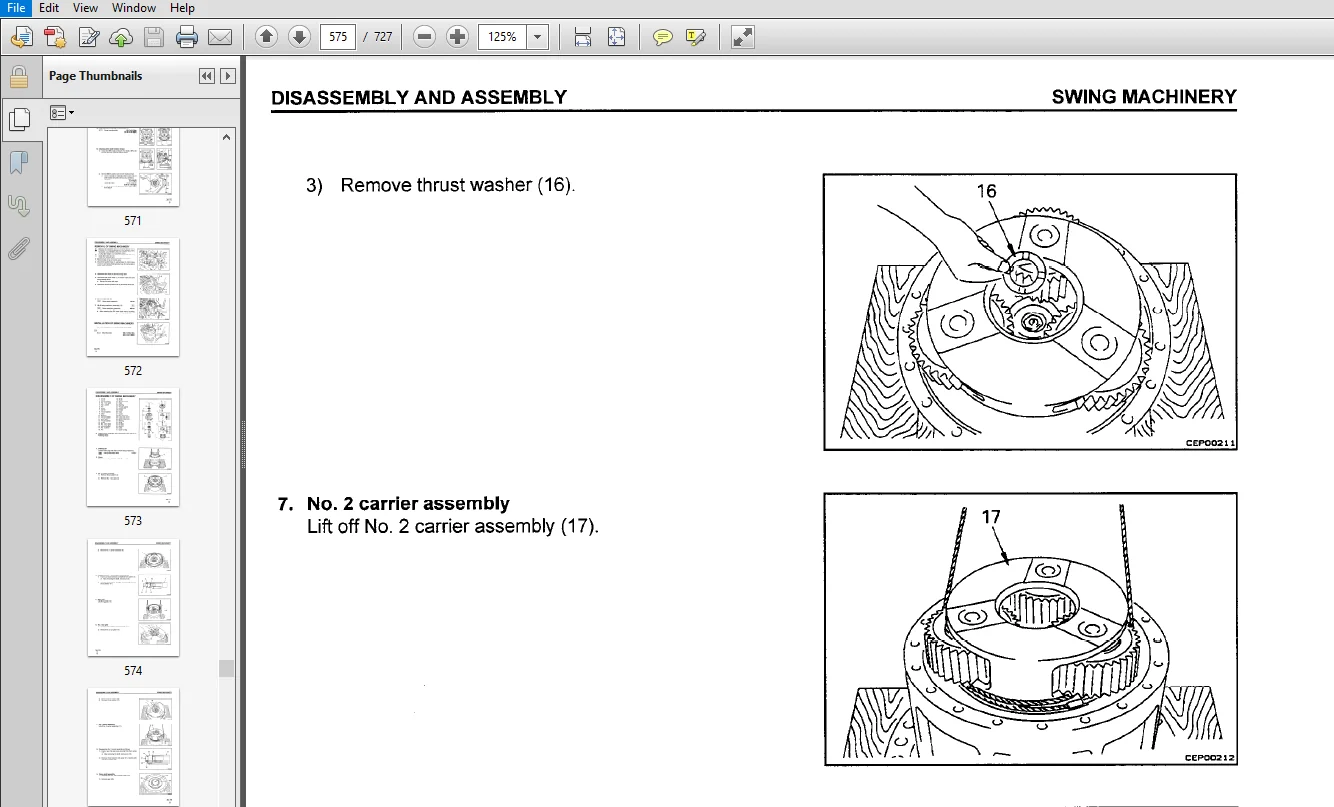
This section explains the order to be followed when removing, installing, disassembling or assembling each component, as well as precautions to be taken for these operations. - MAINTENANCE STANDARD
This section gives the judgement standards when inspecting disassembled parts.
TABLE OF CONTENTS:
KOMATSU PC400LC-6 PC400HD-6 HYDRAULIC EXCAVATOR SERVICE REPAIR MANUAL (Sn:A80001 and up)
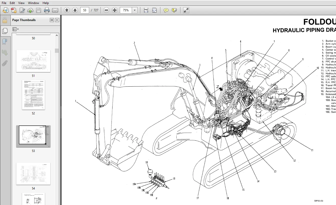
MAIN MENU...........................................................................................................................................  0
CONTENTS............................................................................................................................................  2
01 GENERAL.......................................................................................................................................... 24
	SPECIFICATION DRAWINGS.......................................................................................................................... 25
	SPECIFICATIONS.................................................................................................................................. 29
	WEIGHT TABLE.................................................................................................................................... 31
	FUEL, COOLANT AND LUBRICANTS.................................................................................................................... 33
	ENGINE OIL SPECIFICATIONS....................................................................................................................... 36
	DIESEL FUEL SPECIFICATIONS...................................................................................................................... 37
	COOLANT SPECIFICATIONS.......................................................................................................................... 38
10 STRUCTURE AND FUNCTION........................................................................................................................... 42
	PARTS RELATED TO ENGINE......................................................................................................................... 43
	RADIATOR, OIL COOLER............................................................................................................................ 45
	POWER TRAIN..................................................................................................................................... 46
	FINAL DRIVE..................................................................................................................................... 47
	SWING CIRCLE.................................................................................................................................... 48
	SWING MACHINERY................................................................................................................................. 49
	TRACK FRAME, RECOIL SPRING - PC400LCC-6......................................................................................................... 50
	TRACK FRAME, RECOIL SPRING FOLDOUT - PC400HD-6.................................................................................................. 51
	TRACK SHOE...................................................................................................................................... 52
	HYDRAULIC PIPING DRAWING........................................................................................................................ 53
	HYDRAULIC CIRCUIT DRAWING....................................................................................................................... 54
	HYDRAULIC TANK, HYDRAULIC FILTER................................................................................................................ 55
	HYDRAULIC PUMP.................................................................................................................................. 56
	CONTROL VALVE................................................................................................................................... 77
	SUCTION SAFETY VALVE............................................................................................................................ 86
	CLSS............................................................................................................................................ 87
	SWING MOTOR.....................................................................................................................................120
	CENTER SWIVEL JOINT.............................................................................................................................124
	TRAVEL MOTOR....................................................................................................................................125
	VALVE CONTROL...................................................................................................................................134
	WORK EQUIPMENT, SWING PPC VALVE.................................................................................................................135
	TRAVEL PPC VALVE................................................................................................................................139
	SERVICE PPC VALVE...............................................................................................................................143
	PPC SAFETY LOCK VALVE...........................................................................................................................146
	PCC ACCUMULATOR.................................................................................................................................146
	PPC SHUTTLE VALVE, TRAVEL JUNCTION VALVE........................................................................................................147
	EPC SOLENOID VALVE..............................................................................................................................154
	BOOM HOLDING VALVE..............................................................................................................................159
	HYDRAULIC CYLINDER..............................................................................................................................162
	WORK EQUIPMENT..................................................................................................................................163
	ACTUAL ELECTRIC WIRING DIAGRAM..................................................................................................................164
	ELECTICAL CIRCUIT DIAGRAM.......................................................................................................................174
	ENGINE CONTROL..................................................................................................................................177
	ELECTRICAL CONTROL SYSTEM.......................................................................................................................184
	MACHINE MONITOR SYSTEM..........................................................................................................................207
20 TESTING AND ADJUSTMENT...........................................................................................................................214
	STANDARD VALUE TABLE FOR ENGINE.................................................................................................................215
	STANDARD VALUE TABLE FOR CHASSIS PARTS..........................................................................................................216
	STANDARD VALUE TABLE FOR ELECTRICAL PARTS.......................................................................................................224
	TOOLS FOR TESTING, ADJUSTING AND TROUBLESHOOTING................................................................................................232
	MEASURING ENGINE SPEED..........................................................................................................................233
	MEASURING INTAKE MANIFOLD PRESSURE..............................................................................................................234
	MEASURING INTAKE AIR RESTRICTION................................................................................................................234
	MEASURING LUBRICATING OIL PRESSURE..............................................................................................................234
	MEASURING FUEL (FILTER) INLET RESTRICTION.......................................................................................................234
	MEASURING BLOWBY PRESSURE.......................................................................................................................235
	MEASURING ENGINE BACK PRESSURE..................................................................................................................235
	MEASURING EXHAUST COLOR.........................................................................................................................235
	MEASURING COOLANT TEMPERATURE...................................................................................................................236
	MEASURING VALVE CLEARANCE.......................................................................................................................236
	BELT TENSION....................................................................................................................................237
	GOVERNOR MOTOR LEVER STROKE.....................................................................................................................238
	TESTING AND ADJUSTING HYDRAULIC PRESSURE IN WORK EQUIPMENT, SWING, TRAVEL CIRCUIT...............................................................239
	TESTING AND ADJUSTING TVC VALVE OUTPUT PRESSURE (SERVO PISTON INPUT PRESSURE)...................................................................242
	TESTING AND ADJUSTING LS VALVE OUTPUT PRESSURE (SERVO PISTON INPUT PRESSURE) AND LS DIFFERENTAIL PRESSURE.......................................244
	TESTING AND ADJUSTING CONTROL PUMP CIRCUIT OIL PRESSURE.........................................................................................247
	TESTING SOLENOID VALVE OUTPUT PRESSURE..........................................................................................................249
	MEASURING PPC VALVE OUTPUT PRESSURE AND TESTING PPC SHUTTLE VALVE...............................................................................251
	ADJUSTING WORK EQUIPMENT, SWING PPC VALVE.......................................................................................................253
	TESTING TRAVEL DEVIATION........................................................................................................................254
	TESTING LOCATIONS CAUSING HYDRAULIC DRIFT OF WORK EQUIPMENT.....................................................................................255
	MEASURING OIL LEAKAGE...........................................................................................................................257
	RELEASING REMAINING PRESSURE IN HYDRAULIC CIRCUIT...............................................................................................259
	TESTING CLEARANCE OF SWING CIRCLE BEARING.......................................................................................................260
	TESTING AND ADJUSTING TRACK SHOE TENSION........................................................................................................261
	BLEEDING AIR....................................................................................................................................262
	TROUBLESHOOTING.................................................................................................................................264
		POINTS TO REMEMBER WHEN TROUBLESHOOTING.....................................................................................................265
		SEQUENCE OF EVENTS IN TROUBLESHOOTING.......................................................................................................266
		POINTS TO REMEMBER WHEN CARRYING OUT MAINTENANCE............................................................................................267
		CHECKS BEFORE TROUBLESHOOTING...............................................................................................................276
		CONNECTOR TYPES AND MOUNTING LOCATIONS......................................................................................................277
		CONNECTOR ARRANGEMENT DIAGRAM...............................................................................................................281
		CONNECTION TABLE FOR CONNECTOR PIN NUMBERS..................................................................................................290
		EXPLANATION OF CONTROL MECHANISM FOR ELECTRICAL SYSTEM......................................................................................301
		DISPLAY METHOD AND SPECIAL FUNCTION OF MONITORING PANEL.....................................................................................302
		METHOD OF USING JUDGEMENT TABLE.............................................................................................................310
		METHOD OF USING TROUBLESHOOTING CHARTS......................................................................................................312
		DETAILS OF TROUBLESHOOTING AND TROUBLESHOOTING PROCEDURE....................................................................................314
		SERVICE CODE TABLE..........................................................................................................................319
		TROUBLESHOOTING OF COMMUNICATION ABNORMALITY SYSTEM (N MODE)................................................................................320
			N-1 [E218] Communication abnormality....................................................................................................321
		TROUBLESHOOTING OF GOVERNOR PUMP CONTROLLER (GOVERNOR CONTROL SYSTEM) (E MODE)..............................................................323
			POINTS TO REMEMBER WHEN CARRYING OUT TROUBLESHOOTING OF GOVERNOR, PUMP CONTROLLER SYSTEM................................................324
			ACTIONS TAKEN BY CONTROLLER WHEN ABNORMALITY OCCURS AND PROBLEMS ON MACHINE.............................................................325
			JUDGEMENT TABLE FOR GOVERNOR, PUMP GOVERNOR (GOVERNOR CONTROL SYSTEM) AND RELATED PARTS.................................................329
			ELECTRICAL CIRCUIT DIAGRAM FOR E MODE SYSTEM............................................................................................331
				E-1 Abnormality in governor, pump controller power source (controller LED is OFF)...................................................333
				E-2 [E308] Abnormality in fuel control dial input value is displayed................................................................334
				E-3 [317] Abnormality (disconnection) in motor drive system is displayed............................................................335
				E-4 [318] Abnormality (short circuit) in motor drive system is displayed............................................................336
				E-5 [E306] Abnormality in feedback potentiometer system is displayed................................................................337
				E-6 [E315] Abnormality (short circuit) in battery relay output system is displayed..................................................338
				E-7 [E316] Abnormality (step-out) in motor displayed................................................................................339
				E-8 Engine does not start...........................................................................................................340
				E-9 Engine speed is irregular.......................................................................................................342
				E-10 Lack of output (engine high idling speed is to low)............................................................................346
				E-11 Engine does not stop...........................................................................................................348
				E-12 Defective operation of battery relay system (engine does not stop).............................................................350
		TROUBLESHOOTING OF ENGINE SYSTEM............................................................................................................352
			METHOD OF USING TROUBLESHOOTING CHARTS..................................................................................................353
			S-1 Starting performance is poor (starting always takes time)...........................................................................357
			S-2 Engine does not start...............................................................................................................358
			S-3 Engine does not pick up smoothly (follow up is poor)................................................................................361
			S-4 Engine stops during operations......................................................................................................362
			S-5 Engine does not rotate smoothly (hunting)...........................................................................................363
			S-6 Engine lacks output (no power)......................................................................................................364
			S-7 Engine smoke is black (incomplete combustion).......................................................................................365
			S-8 Oil consumption is excessive (or exhaust smoke is blue).............................................................................366
			S-9 Oil becomes contaminated quickly....................................................................................................366
			S-10 Fuel consumption is excessive......................................................................................................366
			S-11 Oil is in cooling water, or water spurts back, or water level goes down............................................................366
			S-12 Oil pressure caution lamp lights up (drop in oil pressure).........................................................................366
			S-13 Oil level rises (water, fuel in oil)...............................................................................................367
			S-14 Water temperature becomes too high (overheating)...................................................................................368
			S-15 Abnormal noise is made.............................................................................................................369
			S-16 Vibration is excessive.............................................................................................................370
		TROUBLESHOOTING OF GOVERNOR, PUMP CONTROLLER (PUMP CONTROL SYSTEM (C MODE)..................................................................371
			POINT TO REMEMBER WHEN TROUBLESHOOTING PUMP CONTROLLER SYSTEM...........................................................................372
			ACTION TAKEN BY CONTROLLER WHEN ABNORMALITY OCCURS AND PROBLEMS ON MACHINE..............................................................373
			JUDGEMENT TABLE FOR GOVERNOR, PUMP CONTROLLER (PUMP CONTROL SYSTEM) AND HYDRAULIC RELATED PARTS.........................................379
			ELECTRICAL CIRCUIT DIAGRAM FOR C MODE...................................................................................................381
				C-1 Abnormality in controller power source system (controller LED is OFF)...........................................................383
				C-2 [E232] Short Circuit in front pump TVC solenoid system is displayed.............................................................384
				C-3 [E233] Disconnection in front pump TVC solenoid system is displayed.............................................................386
				C-4 [E236] Short circuit in rear pump TVC solenoid system is displayed..............................................................388
				C-5 [E237] Disconnection in rear pump TVC solenoid system is displayed..............................................................390
				C-6 [E202] Short circuit in LS select solenoid system is displayed..................................................................392
				C-7 [E212] Disconnection in LS select solenoid system is displayed..................................................................393
				C-8 [E203[ Short circuit in swing brake solenoid system is displayed................................................................394
				C-9 [E213] Disconnection in swing brake solenoid system is displayed................................................................396
				C-10 [E204] Short circuit in pump merge/divider solenoid system is displayed........................................................398
				C-11 [E214] Disconnection in pump merge/divider solenoid system is displayed........................................................399
				C-12 [E206] Short circuit in travel speed solenoid system is displayed..............................................................400
				C-13 [E216] Disconnection in travel speed selector solenoid system is displayed.....................................................401
				C-14 [E217] Model selection input error is displayed................................................................................402
				C-15 [E222] Short circuit in LS-EPC solenoid system is displayed....................................................................404
				C-16 [E223] Disconnection in LS-EPC solenoid system is displayed....................................................................405
				C-17 [E224] Abnormality in front pump pressure sensor system is displayed...........................................................406
				C-18 [E225] Abnormality in rear pump pressure sensor system is displayed............................................................407
				C-19 [E226] Abnormality in pressure sensor power source system is displayed.........................................................408
				C-20 [E227] Abnormality in engine speed sensor system is displayed..................................................................409
				C-21 Abnormality in machine push up solenoid system (no service code is displayed...................................................410
		TROUBLESHOOTING OF GOVERNOR, PUMP CONTROLLER (INPUT SIGNAL SYSTEM) (F  MODE)................................................................412
			ELECTRICAL CIRCUIT DIAGRAM FOR F MODE...................................................................................................413
				F-1 Bit pattern 20-(1) Swing oil pressure switch does not light up..................................................................415
				F-2 Bit pattern 20-(2) Travel oil pressure switch does not light up.................................................................416
				F-3 Bit pattern 20-(3) Boom LOWER oil pressure switch does not light up.............................................................417
				F-4 Bit pattern 20-(4) Boom RAISE oil pressure switch does not light up.............................................................418
				F-5 Bit pattern 20-(5) Arm IN oil pressure switch does not light up.................................................................419
				F-6 Bit pattern 20-(6) Arm OUT oil pressure switch, does not light up...............................................................420
				F-7 Bit pattern 21-(1) Bucket CURL oil pressure switch does not light up............................................................421
				F-8 Bit pattern 21-(2) Bucket DUMP oil pressure switch does not light up............................................................422
				F-9 Bit pattern 21-(3) Swing lock switch does not light up..........................................................................423
				F-11 Bit pattern 22-(6) L.H. knob switch does not light up..........................................................................424
		TROUBLESHOOTING OF HYDRAULIC, MECHANICAL SYSTEM (H MODE)....................................................................................425
			PUMP MERGE/DIVIDER LOGIC................................................................................................................426
			LS SELECT LOGIC.........................................................................................................................427
			SOLENOID ACTUATION TABLE................................................................................................................427
			TABLE OF FAILURE MODES AND CAUSES.......................................................................................................428
				H-1 Speeds of all work equipment, swing, travel are slow or lack power..............................................................432
				H-2 There is excessive drop in engine speed, or engine stalls.......................................................................434
				H-3 No work equipment, travel, swing move...........................................................................................435
				H-4 Abnormal noise generated (around pump)..........................................................................................435
				H-5 Auto-deceleration does not work (when PPC shuttle valve is cause)...............................................................436
				H-6 Fine control ability is poor or response is poor................................................................................437
				H-7 Boom is slow or lacks power.....................................................................................................438
				H-8 Arm is slow or lacks power......................................................................................................440
				H-9 Bucket is slow or lacks power...................................................................................................442
				H-10 Work equipment (boom, arm, bucket) does not move (but travel and swing are normal).............................................443
				H-11 Excessive hydraulic drift (boom, arm, bucket)..................................................................................443
				H-12 Excessive time lag (engine at low idling)......................................................................................444
				H-13 Other equipment moves when single circuit is relieved..........................................................................444
				H-14 In L/O, F/O modes, work equipment speed is faster than specified speed.........................................................445
				H-15 Defective actuation of machine push-up function................................................................................445
				H-16 In compound operations, work equipment with larger load is slow................................................................445
				H-17 In swing + boom RAISE, boom RAISE is slow......................................................................................446
				H-18 In swing + arm, arm is slow....................................................................................................446
				H-19 In swing + travel, travel speed drops excessively..............................................................................446
				H-20 Travel deviation...............................................................................................................447
				H-21 Travel speed is slow...........................................................................................................448
				H-22 Steering does not turn easily or lacks power...................................................................................450
				H-23 Travel speed does not switch or is faster than specified speed.................................................................452
				H-24 Travel does not move (one side only)...........................................................................................452
				H-25 Does not swing.................................................................................................................453
				H-26 Swing acceleration is poor or swing speed is slow..............................................................................454
				H-27 Excessive overrun when stopping swing..........................................................................................456
				H-28 Excessive shock when stopping swing (one direction only).......................................................................457
				H-29 Excessive abnormal noise when stopping swing...................................................................................457
				H-30 Excessive hydraulic drift of swing.............................................................................................458
				H-31 Swing speed is faster than specified swing speed...............................................................................459
		TROUBLESHOOTING OF HYDRAULIC, MONITOR SYSTEM (M MODE).......................................................................................460
			ACTION TAKEN BY MONITOR PANEL WHEN ABNORMALITY OCCURS AND PROBLEMS ON MACHINE...........................................................461
			ELECTRICAL CIRCUIT DIAGRAM FOR M MODE...................................................................................................463
				M-1 [E101] Abnormality in error data is displayed...................................................................................466
				M-2 [E103] Short circuit in buzzer output or contact of 24V wiring harness with buzzer drive harness is displayed...................467
				M-3 [E104] Air cleaner clogging detected is displayed...............................................................................468
				M-5 [E108] Engine water temperature 105°C detected is displayed.....................................................................468
				M-6 When starting switch is turned ON, none of lamps on monitor panel light up for 3 seconds .......................................469
				M-7 When starting switch is turned ON, monitor panel lamps all stay lighted up and do not go out....................................471
				M-8 When starting switch is turned ON, items lighted up on monitor panel are different from actual machine(mode)....................471
				M-9 When starting switch is turned ON (engine stopped), basic check items flashes...................................................472
				M-11 When starting switch is turned ON and engine is started, basic check item flash................................................475
				M-12 When starting switch is turned ON (engine speed), caution items, emergency items flash (battery, engine oil pressure lamp n....477
				M-13 When starting switch is turned ON and engine is started, caution items, emergency items flash (when there is no abnormality....479
				M-14 When staring switch is turned ON (engine stopped), buzzer does not sound for 1 second Caution item flashes but does not sou....482
				M-15 No abnormality is displayed on monitor but buzzer sounds.......................................................................482
				M-16 Night light on monitor panel does not light up (liquid crystal display is normal)..............................................483
				M-17 Coolant temperature gauge does not rise........................................................................................484
				M-18 Coolant temperature gauge does not give any display (none of gauge lamps light up during operation)............................484
				M-19 Fuel level gauge always displays FULL..........................................................................................485
				M-20 Fuel level gauge does not give display.........................................................................................485
				M-21 Swing lock switch is turned ON (LOCK) but 4 swing lock monitor) does not light up..............................................486
				M-22 Swing prolix switch is turned ON (prolix) but 8 (swing lock monitor) does not flash............................................486
				M-23 Service meter does not advance while engine is running.........................................................................487
				M-24 When starting switch is at OFF and time switch is pressed, time and service meter are not displayed............................487
				M-25 Defective fuel level sensor system.............................................................................................488
				M-26 Defective coolant temperature sensor system....................................................................................489
				M-27 Defective engine oil level sensor system.......................................................................................490
				M-28 Defective coolant level sensor system..........................................................................................491
				M-29 Defective hydraulic oil level sensor system....................................................................................492
				M-30 Wiper does not work or switch is not being used but wiper is actuated..........................................................493
30 DISASSEMBLY AND ASSEMBLY.........................................................................................................................497
	METHOD OF USING MANUAL..........................................................................................................................499
	PRECAUTIONS WHEN CARRYING OUT OPERATION.........................................................................................................501
	SPECIAL TOOL LIST...............................................................................................................................503
	SKETCHES OF SPECIAL TOOLS.......................................................................................................................509
	STARTING MOTOR..................................................................................................................................517
	ALTERNATOR......................................................................................................................................517
	ENGINE OIL COOLER...............................................................................................................................517
	FUEL INJECTION PUMP.............................................................................................................................517
	WATER PUMP......................................................................................................................................518
	NOZZLE HOLDER...................................................................................................................................518
	TURBOCHARGER....................................................................................................................................518
	THERMOSTAT......................................................................................................................................518
	ENGINE FRONT SEAL...............................................................................................................................519
	ENGINE REAR SEAL................................................................................................................................519
	CYLINDER HEAD...................................................................................................................................519
	AFTER COOLER....................................................................................................................................519
	GOVERNOR MOTOR..................................................................................................................................520
		REMOVAL.....................................................................................................................................520
		INSTALLATION................................................................................................................................520
	HYDRAULIC COOLER................................................................................................................................521
		REMOVAL.....................................................................................................................................521
		INSTALLATION................................................................................................................................522
	RADIATOR, HYDRAULIC COOLER......................................................................................................................523
		REMOVAL.....................................................................................................................................523
		INSTALLATION................................................................................................................................524
	ENGINE, MAIN PUMP...............................................................................................................................525
		REMOVAL.....................................................................................................................................525
		INSTALLATION................................................................................................................................528
	DAMPER..........................................................................................................................................529
		REMOVAL.....................................................................................................................................529
		INSTALLATION................................................................................................................................529
	FUEL TANK.......................................................................................................................................530
		REMOVAL.....................................................................................................................................530
		INSTALLATION................................................................................................................................530
	CENTER SWIVEL JOINT.............................................................................................................................531
		REMOVAL.....................................................................................................................................531
		INSTALLATION................................................................................................................................531
		DISASSEMBLY.................................................................................................................................532
		ASSEMBLY....................................................................................................................................532
	FINAL DRIVE.....................................................................................................................................533
		REMOVAL.....................................................................................................................................533
		INSTALLATION................................................................................................................................533
		DISASSEMBLY.................................................................................................................................534
		ASSEMBLY....................................................................................................................................538
	TRAVEL MOTOR....................................................................................................................................545
		DISASSEMBLY.................................................................................................................................545
		ASSEMBLY....................................................................................................................................549
	SPROCKET........................................................................................................................................560
		REMOVAL.....................................................................................................................................560
		INSTALLATION................................................................................................................................560
	SWING MOTOR.....................................................................................................................................561
		REMOVAL.....................................................................................................................................561
		INSTALLATION................................................................................................................................561
		DISASSEMBLY.................................................................................................................................562
		ASSEMBLY....................................................................................................................................565
	SWING MACHINERY.................................................................................................................................572
		REMOVAL.....................................................................................................................................572
		INSTALLATION................................................................................................................................572
		DISASSEMBLY.................................................................................................................................573
		ASSEMBLY....................................................................................................................................577
	REVOLVING FRAME.................................................................................................................................582
		REMOVAL.....................................................................................................................................582
		INSTALLATION................................................................................................................................583
	SWING CIRCLE....................................................................................................................................584
		REMOVAL.....................................................................................................................................584
		INSTALLATION................................................................................................................................584
	IDLER, RECOIL SPRING............................................................................................................................585
		REMOVAL.....................................................................................................................................585
		INSTALLATION................................................................................................................................585
	IDLER...........................................................................................................................................586
		DISASSEMBLY.................................................................................................................................586
		ASSEMBLY....................................................................................................................................587
	RECOIL SPRING...................................................................................................................................589
		DISASSEMBLY.................................................................................................................................589
		ASSEMBLY....................................................................................................................................590
	TRACK ROLLER....................................................................................................................................591
		REMOVAL.....................................................................................................................................591
		INSTALLATION................................................................................................................................591
		DISASSEMBLY.................................................................................................................................592
		ASSEMBLY....................................................................................................................................593
	CARRIER ROLLER..................................................................................................................................595
		REMOVAL.....................................................................................................................................595
		INSTALLATION................................................................................................................................595
		DISASSEMBLY.................................................................................................................................596
		ASSEMBLY....................................................................................................................................597
	TRACK SHOE......................................................................................................................................600
		REMOVAL.....................................................................................................................................600
		INSTALLATION................................................................................................................................600
	HYDRAULIC TANK..................................................................................................................................601
		REMOVAL.....................................................................................................................................601
		INSTALLATION................................................................................................................................602
	CONTROL PUMP....................................................................................................................................603
		REMOVAL.....................................................................................................................................603
		INSTALLATION................................................................................................................................603
	MAIN PUMP.......................................................................................................................................604
		REMOVAL.....................................................................................................................................604
		INSTALLATION................................................................................................................................605
		DISASSEMBLY.................................................................................................................................606
		ASSEMBLY....................................................................................................................................612
		CHECKING CONTACT............................................................................................................................622
	MAIN PUMP INPUT SHAFT OIL SEAL..................................................................................................................624
		REMOVAL.....................................................................................................................................624
		INSTALLATION................................................................................................................................624
	CONTROL VALVE...................................................................................................................................625
		REMOVAL.....................................................................................................................................625
		INSTALLATION................................................................................................................................627
		DISASSEMBLY.................................................................................................................................628
		ASSEMBLY....................................................................................................................................631
	PUMP MERGE/DIVIDER VALVE........................................................................................................................635
		DISASSEMBLY.................................................................................................................................635
		ASSEMBLY....................................................................................................................................635
	PRESSURE COMPENSATION VALVE.....................................................................................................................636
		DISASSEMBLY.................................................................................................................................636
		ASSEMBLY....................................................................................................................................636
	SERVO VALVE FOR FRONT PUMP......................................................................................................................637
		REMOVAL.....................................................................................................................................637
		INSTALLATION................................................................................................................................637
	SERVO VALVE FOR REAR PUMP.......................................................................................................................638
		REMOVAL.....................................................................................................................................638
		INSTALLATION................................................................................................................................638
	LS-EPC SOLENOID VALVE...........................................................................................................................639
		REMOVAL.....................................................................................................................................639
		INSTALLATION................................................................................................................................639
	SOLENOID VALVE..................................................................................................................................640
		REMOVAL.....................................................................................................................................640
		INSTALLATION................................................................................................................................640
	WORK EQUIPMENT PPC VALVE........................................................................................................................641
		REMOVAL.....................................................................................................................................641
		INSTALLATION................................................................................................................................641
		DISASSEMBLY.................................................................................................................................642
		ASSEMBLY....................................................................................................................................642
	TRAVEL PPC VALVE................................................................................................................................643
		REMOVAL.....................................................................................................................................643
		INSTALLATION................................................................................................................................643
		DISASSEMBLY.................................................................................................................................644
		ASSEMBLY....................................................................................................................................645
	PPC SHUTTLE VALVE...............................................................................................................................646
		REMOVAL.....................................................................................................................................646
		INSTALLATION................................................................................................................................647
		DISASSEMBLY.................................................................................................................................648
		ASSEMBLY....................................................................................................................................649
	BOOM LOCK VALVE.................................................................................................................................650
		REMOVAL.....................................................................................................................................650
		INSTALLATION................................................................................................................................650
		DISASSEMBLY.................................................................................................................................650
		ASSEMBLY....................................................................................................................................650
	BOOM CYLINDER...................................................................................................................................651
		REMOVAL.....................................................................................................................................651
		INSTALLATION................................................................................................................................652
	ARM CYLINDER....................................................................................................................................653
		REMOVAL.....................................................................................................................................653
		INSTALLATION................................................................................................................................654
	BUCKET CYLINDER.................................................................................................................................655
		REMOVAL.....................................................................................................................................655
		INSTALLATION................................................................................................................................656
	HYDRAULIC CYLINDER..............................................................................................................................657
		DISASSEMBLY.................................................................................................................................657
		ASSEMBLY....................................................................................................................................659
	WORK EQUIPMENT..................................................................................................................................661
		REMOVAL.....................................................................................................................................661
		INSTALLATION................................................................................................................................662
	BUCKET..........................................................................................................................................663
		REMOVAL.....................................................................................................................................663
		INSTALLATION................................................................................................................................664
	ARM.............................................................................................................................................665
		REMOVAL.....................................................................................................................................665
		INSTALLATION................................................................................................................................666
	BUCKET, ARM.....................................................................................................................................667
		REMOVAL.....................................................................................................................................667
		INSTALLATION................................................................................................................................668
	BOOM............................................................................................................................................669
		REMOVAL.....................................................................................................................................669
		INSTALLATION................................................................................................................................670
	OPERATORS CAB...................................................................................................................................671
		REMOVAL.....................................................................................................................................671
		INSTALLATION................................................................................................................................672
	COUNTERWEIGHT...................................................................................................................................673
		REMOVAL.....................................................................................................................................673
		INSTALLATION ...............................................................................................................................673
	COUNTERWEIGHT WITH COUNTERWEIGHT REMOVER........................................................................................................674
		REMOVAL.....................................................................................................................................674
		INSTALLATION................................................................................................................................677
	AIR CONDITIONER COMPRESSOR......................................................................................................................678
		REMOVAL.....................................................................................................................................678
		INSTALLATION................................................................................................................................678
	CONDENSER.......................................................................................................................................679
		REMOVAL.....................................................................................................................................679
		INSTALLATION................................................................................................................................679
	AIR CONDITIONER.................................................................................................................................680
		REMOVAL.....................................................................................................................................680
		INSTALLATION................................................................................................................................681
	GOVERNOR, PUMP CONTROLLER.......................................................................................................................682
		REMOVAL.....................................................................................................................................682
		INSTALLATION................................................................................................................................682
	MONITOR PANEL...................................................................................................................................683
		REMOVAL.....................................................................................................................................683
		INSTALLATION................................................................................................................................683
	CONTROL STAND CASE..............................................................................................................................684
		REMOVAL.....................................................................................................................................684
		INSTALLATION................................................................................................................................685
40 MAINTENANCE STANDARD.............................................................................................................................686
	ENGINE MOUNT....................................................................................................................................687
	RADIATOR AND OIL COOLER.........................................................................................................................688
	SWING MACHINERY.................................................................................................................................689
	FINAL DRIVE.....................................................................................................................................691
	SWING CIRCLE....................................................................................................................................693
	TRACK FRAME AND RECOIL SPRING - PC400LC-6.......................................................................................................694
	TRACK FRAME AND RECOIL SPRING - PC400HD-6.......................................................................................................695
	CARRIER ROLLER..................................................................................................................................697
	IDLER...........................................................................................................................................698
	TRACK...........................................................................................................................................700
	TRACK ROLLER....................................................................................................................................702
	HYDRAULIC PUMP..................................................................................................................................703
	CONTROL PUMP AND RELIEF VALVE...................................................................................................................704
	CONTROL VALVE...................................................................................................................................705
	SUCTION SAFETY VALVE............................................................................................................................711
	SWING MOTOR.....................................................................................................................................712
	TRAVEL MOTOR....................................................................................................................................713
	WORK EQUIPMENT, SWING PPC VALVE.................................................................................................................714
	TRAVEL PPC VALVE................................................................................................................................715
	SERVICE PPC VALVE...............................................................................................................................716
	PPC SHUTTLE VALVE, TRAVEL JUNCTION VALVE........................................................................................................717
	EPC SOLENOID VALVE..............................................................................................................................718
	CENTER SWIVEL JOINT.............................................................................................................................719
	BOOM HOLDING VALVE..............................................................................................................................720
	HYDRAULIC CYLINDER..............................................................................................................................721
	WORK EQUIPMENT..................................................................................................................................723
	DIMENSIONS OF WORK EQUIPMENT....................................................................................................................725
PLEASE NOTE:
⦁ This is the SAME exact manual used by your dealers to fix your vehicle.
⦁ The same can be yours in the next 2-3 mins as you will be directed to the download page immediately after paying for the manual.
⦁ Any queries / doubts regarding your purchase, please feel free to contact [email protected]


