Komatsu PC490LC-10 Hydraulic Excavator Shop Manual – PDF DOWNLOAD
Original price was: $68.95.$27.95Current price is: $27.95.
Komatsu PC490LC-10 Hydraulic Excavator Shop Manual
SERIAL NUMBERS : PC490LC-10 A40001 and up
Description
Komatsu PC490LC-10 Hydraulic Excavator Shop Manual
FILE DETAILS:
Komatsu PC490LC-10 Hydraulic Excavator Shop Manual
Brands: Komatsu
Equipment Type: Hydraulic Excavator
Manuals Type: Shop Manual
Machine Model: PC490LC-10
Serial Number: A40001 and up
Book Code: CEBM025303
Language: English
Pages: 1815
File Format: Portable Document Format (PDF)
DESCRIPTION:
Komatsu PC490LC-10 Hydraulic Excavator Shop Manual
1 GENERAL:
This shop manual has been prepared as an aid to improve the quality of repairs by giving the serviceman an accurate understanding of the product and by showing him the correct way to perform repairs and make judgements. Make sure you understand the contents of this manual and use it to full effect at every opportunity. This shop manual mainly contains the necessary technical information for operations performed in a service workshop. For ease of understanding, the manual is divided into the following sections. These sections are further divided into each main group of components.
01 GENERAL:
This section lists the general machine dimensions, performance specifications, component weights, and fuel, coolant and lubricant specification charts.
10 STRUCTURE AND FUNCTION:
This section explains the structure and function of each component. It serves not only to give an understanding of the structure, but also serves as reference material for troubleshooting.
20 STANDARD VALUE TABLE:
This section explains the standard values for new machine and judgement criteria for testing, adjusting and troubleshooting. This standard value table is used to check the standard values in testing and adjusting and to judge parts in troubleshooting.
30 TESTING AND ADJUSTING:
This section explains checks to be made before and after performing repairs, as well as adjustments to be made at completion of the checks and repairs.
40 TROUBLESHOOTING:
This section explains how to find out failed parts and how to repair them. The troubleshooting is divided by failure modes. The “S mode” of the troubleshooting related to the engine may be also explained in the
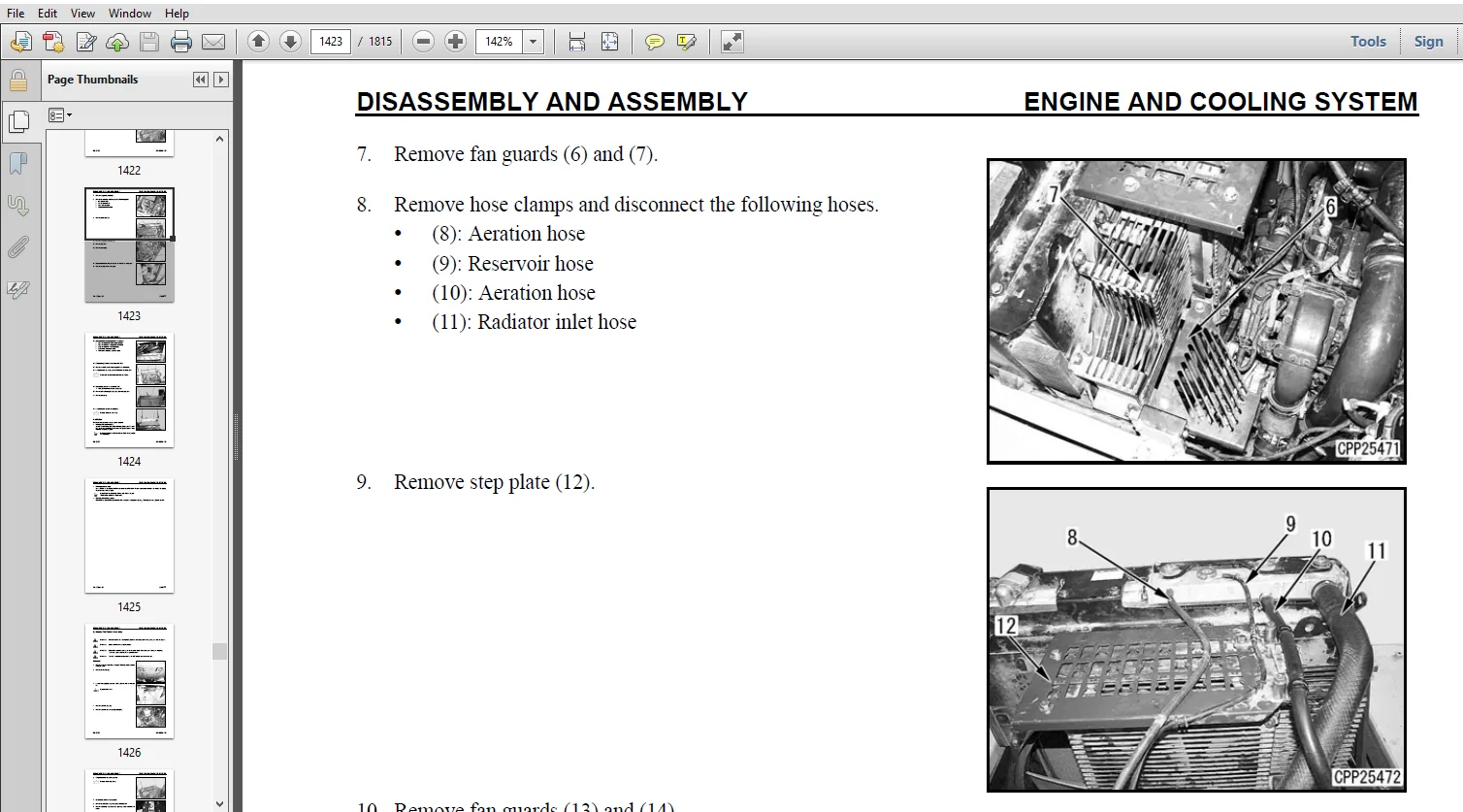
50 DISASSEMBLY AND ASSEMBLY
This section explains the order to be followed when removing, installing, disassembling or assembling each component, as well as precautions to be taken for these operations.
60 MAINTENANCE STANDARD
This section gives the judgement standards when inspecting disassembled parts.
80 AIR CONDITIONING
This section explains the air conditioning system, structure and function, troubleshooting, disassembly, and assembly.
90 DIAGRAMS AND DRAWINGS
This section has the foldout drawings for the machine.
TABLE OF CONTENTS:
Komatsu PC490LC-10 Hydraulic Excavator Shop Manual
CEBM025303................................................................................................................................   1
CONTENTS..................................................................................................................................   2
SAFETY....................................................................................................................................  17
	Safety Notice.........................................................................................................................  17
		Important Safety Notice...........................................................................................................  17
		General Precautions...............................................................................................................  17
		Preparations For Work.............................................................................................................  19
		Precautions During Work...........................................................................................................  19
GENERAL...................................................................................................................................  22
	HOW TO READ THE SHOP MANUAL...........................................................................................................  24
		Volumes...........................................................................................................................  24
		Distribution And Updating.........................................................................................................  24
		Filing Method.....................................................................................................................  24
		Revised Edition Mark..............................................................................................................  24
		Revisions.........................................................................................................................  24
		Symbols...........................................................................................................................  24
	HOISTING INSTRUCTIONS.................................................................................................................  25
		Hoisting..........................................................................................................................  25
		Making Signs......................................................................................................................  25
		Precautions.......................................................................................................................  25
			Precautions for Sling Work....................................................................................................  25
			Precautions for Using Mobile Crane............................................................................................  26
			Precautions for Using Overhead Hoist Crane....................................................................................  26
		Selecting Wire Ropes..............................................................................................................  27
	HANDLING ELECTRIC EQUIPMENT AND HYDRAULIC COMPONENTS..................................................................................  28
		Points to Remember When Handling Electric Equipment...............................................................................  28
		Points to Remember When Handling Hydraulic Equipment..............................................................................  39
	PUSH PULL COUPLER.....................................................................................................................  41
		Type 1............................................................................................................................  41
			Disconnection.................................................................................................................  41
			Connection....................................................................................................................  41
		Type 2............................................................................................................................  42
			Disconnection.................................................................................................................  42
			Connection....................................................................................................................  42
		Type 3............................................................................................................................  43
			Disconnection.................................................................................................................  43
			Connection....................................................................................................................  43
	EXPLANATION OF MAINTENANCE STANDARD TERMS.............................................................................................  44
	HANDLING OF FUEL SYSTEM DEVICES.......................................................................................................  45
	HANDLING OF INTAKE SYSTEM PARTS.......................................................................................................  46
	STANDARD TIGHTENING TORQUE............................................................................................................  47
		Bolts And Nuts....................................................................................................................  47
		Tightening Torque Of Hose Nuts....................................................................................................  48
		Tightening Torque Of Split Flange Bolts...........................................................................................  48
		Tightening Torque For Flared Nuts.................................................................................................  48
		Tightening Torques for Split Flanged Bolts........................................................................................  49
		Tightening Torques For O-ring Boss Piping Joints..................................................................................  49
		Table Of Tightening Torques For O-ring Boss Plugs.................................................................................  49
		Tightening Torque For Hoses (Taper Seal Type And Face Seal Type)..................................................................  50
			Tightening Torque For Face Seal Joints........................................................................................  50
	ELECTRIC WIRE CODE....................................................................................................................  51
		Classification By Thickness.......................................................................................................  51
		Classification By Color And Code..................................................................................................  51
		How To Read Electric Wire Code....................................................................................................  52
	PRECAUTIONS FOR OPERATIONS............................................................................................................  55
		Precautions when Carrying Out Removal Work........................................................................................  55
		Precautions when Carrying Out Installation Work...................................................................................  56
		Precautions when Completing the Operation.........................................................................................  57
	CONVERSION TABLES.....................................................................................................................  58
		Method Of Using The Conversion Table..............................................................................................  58
	COATING MATERIALS.....................................................................................................................  64
	LIST OF ABBREVIATIONS.................................................................................................................  66
		List of Abbreviations Used in the Shop Manual.....................................................................................  66
		List of Abbreviations Used in the Circuit Diagrams................................................................................  70
01 GENERAL................................................................................................................................  71
	SPECIFICATION DIMENSION DRAWINGS......................................................................................................  72
		Dimensions........................................................................................................................  72
		Working Ranges....................................................................................................................  73
	SPECIFICATIONS........................................................................................................................  74
	WEIGHT TABLE..........................................................................................................................  78
	FUEL, COOLANT AND LUBRICANTS..........................................................................................................  80
10 STRUCTURE, FUNCTION & MAINTENANCE STD..................................................................................................  83
	ENGINE AND COOLING SYSTEM.............................................................................................................  86
		Engine Related Parts..............................................................................................................  86
		Radiator, Oil Cooler and Aftercooler..............................................................................................  88
		Cooling Fan Pump..................................................................................................................  90
			Operation of Pump.............................................................................................................  93
			Control of Delivery...........................................................................................................  96
			Servo Valve...................................................................................................................  97
			Cooling Fan Motor.............................................................................................................  99
		Hydraulic Motor................................................................................................................... 101
			Suction Valve................................................................................................................. 102
			Reversible Valve.............................................................................................................. 104
			Safety Valve.................................................................................................................. 106
	POWER TRAIN SYSTEM.................................................................................................................... 108
		Power Train....................................................................................................................... 108
		Swing Circle...................................................................................................................... 110
		Swing machinery................................................................................................................... 112
		Final Drive....................................................................................................................... 114
	UNDERCARRIAGE AND FRAME............................................................................................................... 116
		Track Frame and Idler Cushion..................................................................................................... 116
	HYDRAULIC SYSTEM...................................................................................................................... 118
		Hydraulic Component Layout........................................................................................................ 118
		Valve Control..................................................................................................................... 120
		Hydraulic Tank.................................................................................................................... 121
			Oil Filler Port Cap........................................................................................................... 122
		CLSS.............................................................................................................................. 124
			Structure of CLSS............................................................................................................. 124
			Basic Principle............................................................................................................... 125
		Main Pump......................................................................................................................... 130
			LS valve...................................................................................................................... 135
			Operation..................................................................................................................... 136
		PC Valve.......................................................................................................................... 140
			Operation..................................................................................................................... 142
			LS(PC)-EPC Valve.............................................................................................................. 148
			Operation..................................................................................................................... 149
		Control Valve..................................................................................................................... 152
			Functions and Operation by Valve.............................................................................................. 164
			Unload Valve.................................................................................................................. 168
			LS Bypass Valve............................................................................................................... 170
			Pressure Compensation Valve................................................................................................... 171
			Pressure Compensation Valve Inner Shuttle Valve............................................................................... 174
			Boom Regeneration Circuit..................................................................................................... 176
			Arm Regeneration Circuit...................................................................................................... 178
			Merge-Divider Valve........................................................................................................... 180
			LS Select Valve............................................................................................................... 183
			Self Pressure Reducing Valve.................................................................................................. 184
			Travel Junction Valve......................................................................................................... 187
			Travel PPC Shuttle Valve...................................................................................................... 190
			Boom Hydraulic Drift Preventive Valve......................................................................................... 192
			Arm Drift Preventive Valve.................................................................................................... 195
			Suction Safety Valve For Drift Prevention Valve............................................................................... 198
			Arm Quick Return Valve........................................................................................................ 199
			Variable Back Pressure Valve.................................................................................................. 201
			Main Relief Valve............................................................................................................. 202
			2-Stage Safety-Suction Valve.................................................................................................. 204
			Swing Motor................................................................................................................... 206
			Swing Holding Brake........................................................................................................... 208
			Swing 2-Stage Relief Valve.................................................................................................... 211
			Swing Motor Reverse Prevention Valve.......................................................................................... 212
		Travel Motor...................................................................................................................... 215
			Operation of Motor............................................................................................................ 218
			Operation of Parking Brake.................................................................................................... 220
			Brake Valve................................................................................................................... 222
			Safety Valve (Bidirectional 2-Stage Set Safety Valve)......................................................................... 223
		PPC Valve......................................................................................................................... 227
			Work Equipment and Swing PPC Valve............................................................................................ 227
		Travel PPC valve.................................................................................................................. 233
		1st-line Attachment PPC Valve (with EPC valve).................................................................................... 237
			EPC valve..................................................................................................................... 238
		Solenoid Valve.................................................................................................................... 242
		Attachment Circuit Selector Valve................................................................................................. 244
		Center Swivel Joint............................................................................................................... 246
			PPC Accumulator............................................................................................................... 247
	WORK EQUIPMENT........................................................................................................................ 248
		Work Equipment.................................................................................................................... 248
			Work Equipment Shims.......................................................................................................... 249
	CAB AND ITS ATTACHMENTS............................................................................................................... 250
		Cab Mount and Cab Tipping Stopper................................................................................................. 250
		ROPS Cab.......................................................................................................................... 251
	ELECTRICAL SYSTEM..................................................................................................................... 252
		Engine Control.................................................................................................................... 252
			Engine Controller Function.................................................................................................... 255
			Engine And Pump Combined Control Function..................................................................................... 258
		Pump and Valve Control Function................................................................................................... 264
			One-touch Power Maximizing Function........................................................................................... 266
			Machine Push-up Function...................................................................................................... 268
			Auto-Deceleration Function.................................................................................................... 270
			Engine Automatic Warm-up Function............................................................................................. 272
			Overheat Prevention Function.................................................................................................. 274
			Turbocharger Protection Function.............................................................................................. 275
			Swing Control Function........................................................................................................ 276
			Quick Warm-Up Function........................................................................................................ 278
			Swing 2-Stage Relief Function................................................................................................. 278
			Travel Control Function....................................................................................................... 280
			PPC Lock Function............................................................................................................. 282
			Oil Flow Adjuster Function For Attachment..................................................................................... 284
		Hydraulic Fan Control Function.................................................................................................... 286
			Fan Rotation Control.......................................................................................................... 286
			Engine Output Control......................................................................................................... 287
			Fan Reverse Rotation Function................................................................................................. 288
			System Component Part......................................................................................................... 290
			Pump Controller............................................................................................................... 294
			Resistor for PC-EPC valve..................................................................................................... 299
			CAN Terminating Resistor...................................................................................................... 300
	MACHINE MONITOR SYSTEM................................................................................................................ 301
		Machine Monitor................................................................................................................... 302
			Input and Output Signals...................................................................................................... 303
			Display....................................................................................................................... 306
			Gauges........................................................................................................................ 308
			Caution Monitor............................................................................................................... 310
			Pilot Monitor................................................................................................................. 314
		Switches.......................................................................................................................... 316
			Guidance ICON and Function Switch............................................................................................. 318
			Operator Mode Function........................................................................................................ 322
			Service Mode Function......................................................................................................... 324
	KOMTRAX SYSTEM........................................................................................................................ 326
		KOMTRAX Terminal.................................................................................................................. 327
		Input and Output Signals.......................................................................................................... 328
	SENSORS............................................................................................................................... 330
		Ambient Pressure Sensor........................................................................................................... 330
		Engine Oil Pressure Sensor........................................................................................................ 331
		Charge Pressure Sensor............................................................................................................ 331
		Charge Temperature Sensor......................................................................................................... 332
		Coolant Temperature Sensor........................................................................................................ 332
		Ne (Crankshaft) Speed Sensor...................................................................................................... 333
		Bkup (Camshaft) Speed Sensor...................................................................................................... 333
		Common Rail Pressure Sensor....................................................................................................... 334
		EGR Valve Lift Sensor............................................................................................................. 335
		KVGT Speed Sensor................................................................................................................. 336
		KVGT Position Sensor.............................................................................................................. 336
		Mass Air Flow and Temperature Sensor.............................................................................................. 337
		Dosing Fuel Pressure Sensor....................................................................................................... 338
		KDPF Differential Pressure and Outlet Pressure Sensor............................................................................. 338
		KDOC Inlet Temperature Sensor..................................................................................................... 339
		KDOC Outlet Temperature Sensor.................................................................................................... 339
		KDPF Outlet Temperature Sensor.................................................................................................... 340
		Crankcase Pressure Sensor......................................................................................................... 340
		Engine Oil Level Sensor........................................................................................................... 341
		Fuel Level Sensor................................................................................................................. 342
		Coolant Level Sensor.............................................................................................................. 343
		Hydraulic Oil Temperature Sensor.................................................................................................. 343
		Front Pump Oil Pressure Sensor.................................................................................................... 344
		Rear Pump Oil Pressure Sensor..................................................................................................... 345
		PPC Oil Pressure Sensor........................................................................................................... 346
		Air Cleaner Clogging Sensor....................................................................................................... 347
		Front Pump Swash Plate Sensor..................................................................................................... 348
		Rear Pump Swash Plate Sensor...................................................................................................... 349
		Cooling Fan Speed Sensor.......................................................................................................... 350
20 STD VALUE TABLES....................................................................................................................... 351
	STANDARD SERVICE VALUE TABLES......................................................................................................... 352
		Standard Value Table for Engine................................................................................................... 352
		Standard Value Table for Machine.................................................................................................. 354
			Engine Speed.................................................................................................................. 354
			Travel of Control Valve Spool................................................................................................. 354
			Travel of Control Lever....................................................................................................... 355
			Operating Effort of Control Lever and Pedal................................................................................... 355
			Hydraulic Oil Pressure........................................................................................................ 356
			Swing......................................................................................................................... 357
			Travel........................................................................................................................ 358
			Work Equipment................................................................................................................ 360
			Performance in Combined Operation............................................................................................. 362
			Pump Swash Plate Sensor....................................................................................................... 362
			Characteristics of PC Flow Control............................................................................................ 362
			Fan........................................................................................................................... 363
			Main Pump..................................................................................................................... 363
		Posture of Machine for Measuring Performance and Measurement Procedure............................................................ 365
			Control Valve: Spool Travel................................................................................................... 365
			Swing 1: Overrun When Stopping Swing, Time Taken to Start Swing, Time Taken to Swing.......................................... 365
			Swing 2: Amount of Hydraulic Drift of Swing................................................................................... 365
			Travel 1: Travel Speed, Idle Running (Without Load)........................................................................... 365
			Travel 2: Travel Speed (Actual Run), Travel Deviation......................................................................... 366
			Travel 3: Travel Deviation.................................................................................................... 366
			Travel 4: Hydraulic Drift of Travel........................................................................................... 366
			Work Equipment 1: Hydraulic Drift of Work Equipment........................................................................... 366
			Work Equipment 2: Boom Speed.................................................................................................. 367
			Work Equipment 3: Arm Speed................................................................................................... 367
			Work Equipment 4: Bucket Speed................................................................................................ 367
			Work Equipment 5: Boom Time Lag............................................................................................... 367
			Work Equipment 6: Arm Time Lag................................................................................................ 368
			Work Equipment 7: Bucket Time Lag............................................................................................. 368
			Work Equipment 8: PC Flow Characteristics Control............................................................................. 368
30 TESTING & ADJUSTING.................................................................................................................... 369
	GENERAL INFORMATION................................................................................................................... 372
		Tools for Testing, Adjusting, and Troubleshooting................................................................................. 372
		Sketch of Tools for Testing and Adjusting......................................................................................... 378
	ENGINE AND COOLING SYSTEM............................................................................................................. 382
		Checking Engine Speed............................................................................................................. 382
		Measuring Boost Pressure.......................................................................................................... 384
		Measuring Exhaust Gas Temperature................................................................................................. 386
		Measuring Exhaust Gas Color....................................................................................................... 388
		Measuring and Adjusting Valve Clearance........................................................................................... 390
			Testing....................................................................................................................... 390
			Adjusting..................................................................................................................... 393
		Measuring Compression Pressure.................................................................................................... 394
		Measuring Engine Oil Pressure..................................................................................................... 399
		Measuring EGR Valve and KVGT Oil Pressure......................................................................................... 401
		Measuring Fuel Pressure........................................................................................................... 403
		Measuring Fuel Leakage and Return................................................................................................. 405
			Testing....................................................................................................................... 405
			Measuring return rate from injector........................................................................................... 407
		Bleeding Air from Fuel System..................................................................................................... 409
			Bleeding Air.................................................................................................................. 410
		Checking Fuel Circuit for Leakage................................................................................................. 413
		Handling Cylinder Cut-Out Mode Operation.......................................................................................... 414
		Handling No-Injection Cranking Operation.......................................................................................... 414
		Checking and Adjusting Air Conditioner Compressor Belt Tension.................................................................... 415
			Checking...................................................................................................................... 415
			Adjusting..................................................................................................................... 416
		Replacing Fan Belt................................................................................................................ 417
			Replacing..................................................................................................................... 417
		Fuel Doser Cleaning Procedure..................................................................................................... 419
			Removal....................................................................................................................... 419
			Cleaning...................................................................................................................... 420
			Installation.................................................................................................................. 422
		Writing Compensation Values at Replacement of Injector and Engine Controller...................................................... 423
			Connection of PC.............................................................................................................. 423
			Starting INSITE............................................................................................................... 424
	POWER TRAIN........................................................................................................................... 429
		Testing Swing Circle Bearing Clearance............................................................................................ 429
			Testing....................................................................................................................... 429
	UNDERCARRIAGE AND FRAME............................................................................................................... 431
		Testing and Adjusting Track Shoe Tension.......................................................................................... 431
			Testing....................................................................................................................... 431
			Adjusting..................................................................................................................... 431
	HYDRAULIC SYSTEM...................................................................................................................... 433
		Releasing Remaining Pressure from Hydraulic Circuit............................................................................... 433
		Measuring and Adjusting of Oil Pressure in Work Equipment, Swing, and Travel Circuits............................................. 435
			Testing....................................................................................................................... 435
			Adjusting..................................................................................................................... 437
		Measuring Oil Pressure in Control Circuit......................................................................................... 441
		Measuring and Adjusting Oil Pressure in Pump PC Control Circuit................................................................... 443
			Testing....................................................................................................................... 443
			Adjusting..................................................................................................................... 445
		Measuring and Adjusting Oil Pressure in Pump LS Control Circuit................................................................... 447
			Testing....................................................................................................................... 447
			Checking Oil Pressure with Sensor Adapter (Special Tool)...................................................................... 451
			Adjusting..................................................................................................................... 452
		Measuring Solenoid Valve Output Pressure.......................................................................................... 453
			Testing....................................................................................................................... 453
			Operating Condition........................................................................................................... 455
		Measuring PPC Valve Output Pressure............................................................................................... 457
		Adjusting Play of Work Equipment and Swing PPC Valves............................................................................. 459
		Testing Pump Swash Plate Sensor................................................................................................... 460
		Measuring Fan Pump Circuit Oil Pressure........................................................................................... 461
		Checking Fan Pump EPC Current..................................................................................................... 462
		Measuring Fan Pump EPC Solenoid Valve Output Pressure............................................................................. 463
		Isolating the Parts Causing Hydraulic Drift in Work Equipment..................................................................... 465
		Measuring Oil Leakage............................................................................................................. 467
		Bleeding Air From Hydraulic Circuit............................................................................................... 471
			Bleeding Air.................................................................................................................. 472
	CAB AND ITS ATTACHMENTS............................................................................................................... 475
		Checking Cab Tipping Stopper...................................................................................................... 475
		Adjusting Mirrors................................................................................................................. 476
	ELECTRICAL SYSTEM..................................................................................................................... 479
		Special Functions of Machine Monitor.............................................................................................. 479
			Upper Part Of Machine Monitor (Display Portion)............................................................................... 480
			Upper Part of Machine Monitor (Switch Portion)................................................................................ 480
			Lower Part of Machine Monitor (Switch Portion)................................................................................ 480
		Ordinary Functions and Special Functions of Machine Monitor....................................................................... 480
			Operator Mode (Outline)....................................................................................................... 483
			Service Mode.................................................................................................................. 502
		Angle Adjustment of Rear View Camera.............................................................................................. 566
		Handling Voltage Circuit of Engine Controller..................................................................................... 568
		Handling Battery Disconnect Switch................................................................................................ 569
		Testing Diodes.................................................................................................................... 570
	PM CLINIC............................................................................................................................. 571
		PM Clinic Service................................................................................................................. 571
			Check Items Related to Engine................................................................................................. 573
			Check Items Related to Oil Pressure........................................................................................... 574
		Check Sheet....................................................................................................................... 575
			1. Engine..................................................................................................................... 575
			2. Work equipment speed....................................................................................................... 576
			3. Hydraulic drift of work equipment.......................................................................................... 576
			4. Hydraulic circuit.......................................................................................................... 577
			Visual Check of Welded Structures............................................................................................. 580
		Undercarriage Inspection Report................................................................................................... 581
40 TROUBLESHOOTING........................................................................................................................ 583
	GENERAL INFORMATION ON TROUBLESHOOTING................................................................................................ 591
		Points to Remember When Troubleshooting........................................................................................... 591
		Sequence of Events in Troubleshooting............................................................................................. 593
		Checks Before Troubleshooting..................................................................................................... 595
		Testing Procedure Before Troubleshooting.......................................................................................... 597
			Walk-Around Check............................................................................................................. 597
			Checking in Accordance with Checking Procedure................................................................................ 599
		Preparation Work for Troubleshooting of Electrical System......................................................................... 605
			Preparation Work.............................................................................................................. 605
		Classification and Procedure for Troubleshooting.................................................................................. 610
			Classification of Troubleshooting............................................................................................. 610
			Procedure for Troubleshooting................................................................................................. 610
		Symptom of Probable Failure and Troubleshooting No................................................................................ 614
		Information Mentioned in Troubleshooting Table.................................................................................... 618
	DIAGNOSTIC PROCEDURE FOR WIRING HARNESS............................................................................................... 620
		Open Circuit Of Pressure Sensor System............................................................................................ 620
		Connector list.................................................................................................................... 623
		Layout of connectors.............................................................................................................. 628
		Connection Table for Connector Pin Numbers........................................................................................ 634
		T-Branch Box and T-Branch Adapter Table........................................................................................... 669
		Fuse List and Location............................................................................................................ 673
			Connection Table of Fuse Box.................................................................................................. 673
			Locations of Fusible Links.................................................................................................... 674
			Location of Fuse Box and Fuse Numbers......................................................................................... 674
		Precautions for Cleaning and Replacing KDPF (KCSF, KDOC).......................................................................... 675
	FAILURE CODE (DISPLAY OF CODE)........................................................................................................ 678
		Failure Codes Table............................................................................................................... 678
		879AKA - Air Conditioner Inner Sensor Disconnection............................................................................... 685
		879AKB - Air Conditioner Inner Sensor Disconnection............................................................................... 685
		879BKA - A/C Outer Sensor Open Circuit............................................................................................ 685
		879BKB - A/C Outer Sensor Short Circuit........................................................................................... 685
		879CKA - Ventilating Sensor Open Circuit.......................................................................................... 685
		879CKB - Ventilating Sensor Short Circuit......................................................................................... 685
		879DKZ - Sunlight Sensor Open or Short Circuit.................................................................................... 685
		879EMC - Ventilation Damper Abnormality........................................................................................... 686
		879FMC - Air Mix Damper Abnormality............................................................................................... 686
		879GKX - Refrigerant Abnormality.................................................................................................. 686
		989L00 - Engine Controller Lock Caution 1......................................................................................... 687
		989M00 - Engine Controller Lock Caution 2......................................................................................... 687
		989N00 - Engine Controller Lock Caution 3......................................................................................... 688
		A1U0N3 - KDPF Dry Request (HC Release) 1.......................................................................................... 689
		A1U0N4 - KDPF Dry Request (HC Release) 2.......................................................................................... 691
		AA10NX - Air Cleaner Clogging..................................................................................................... 694
		AB00KE - Charge Voltage Low....................................................................................................... 696
		B@BAZG - Engine Oil Pressure Low.................................................................................................. 698
		B@BAZK - Eng Oil Level Low........................................................................................................ 700
		B@BCNS - Engine Coolant Overheat.................................................................................................. 702
		B@BCZK - Radiator Coolant Level Low............................................................................................... 704
		B@HANS - Hyd Oil Overheat......................................................................................................... 706
		CA115 - Eng Ne and Bkup Speed Sens Error.......................................................................................... 707
		CA122 - Chg Air Press Sensor High Error........................................................................................... 708
		CA123 - Chg Air Press Sensor Low Error............................................................................................ 710
		CA131 - Throttle Sensor High Error................................................................................................ 712
		CA132 - Throttle Sensor Low Error................................................................................................. 714
		CA135 - Eng Oil Press Sensor High Error........................................................................................... 716
		CA141 - Eng Oil Press Sensor Low Error............................................................................................ 718
		CA144 - Coolant Temp Sens High Error.............................................................................................. 720
		CA145 - Coolant Temp Sens Low Error............................................................................................... 722
		CA153 - Chg Air Temp Sensor High Error............................................................................................ 724
		CA154 - Chg Air Temp Sensor Low Error............................................................................................. 726
		CA187 - Sensor 2 Supply Volt Low Error............................................................................................ 728
		CA221 - Ambient Press Sensor High Error........................................................................................... 730
		CA222 - Ambient Press Sensor Low Error............................................................................................ 732
		CA227 - Sensor 2 Supply Volt High Error........................................................................................... 734
		CA234 - Eng Overspeed............................................................................................................. 735
		CA238 - Ne Speed Sensor Supply Volt Error......................................................................................... 736
		CA239 - Ne Speed Sens Supply Volt High Error...................................................................................... 738
		CA271 - IMV/PCV1 Short Error...................................................................................................... 740
		CA272 - IMV/PCV1 Open Error....................................................................................................... 742
		CA273 - PCV2 Short Error.......................................................................................................... 744
		CA274 - PCV2 Open Error........................................................................................................... 746
		CA322 - Inj #1 (L#1) Open/Short Error............................................................................................. 748
		CA323 - Inj #5 (L#5) Open/Short Error............................................................................................. 750
		CA324 - Inj #3 (L#3) Open/Short Error............................................................................................. 752
		CA325 - Inj #6 (L#6) Open/Short Error............................................................................................. 754
		CA331 - Inj #2 (L#2) Open/Short Error............................................................................................. 756
		CA332 - Inj #4 (L#4) Open/Short Error............................................................................................. 758
		CA343 - ECM Critical Internal Failure............................................................................................. 760
		CA351 - Injectors Drive Circuit Error............................................................................................. 761
		CA352 - Sensor 1 Supply Volt Low Error............................................................................................ 762
		CA356 - Mass Air Flow Sensor High Error........................................................................................... 764
		CA357 - Mass Air Flow Sensor Low Error............................................................................................ 766
		CA386 - Sensor 1 Supply Volt High Error........................................................................................... 768
		CA441 - Battery Voltage Low Error................................................................................................. 770
		CA442 - Battery Voltage High Error................................................................................................ 772
		CA449 - Rail Press Very High Error................................................................................................ 773
		CA451 - Rail Press Sensor High Error.............................................................................................. 774
		CA452 - Rail Press Sensor Low Error............................................................................................... 776
		CA515 - Rail Press Sens Sup Volt Low Error........................................................................................ 778
		CA516 - Rail Press Sens Sup Volt High Error....................................................................................... 780
		CA553 - Rail Press High Error..................................................................................................... 782
		CA555 - Crankcase Press High Error 1.............................................................................................. 783
		CA556 - Crankcase Press High Error 2.............................................................................................. 784
		CA559 - Supply Pump Press Low Error 1............................................................................................. 785
		CA595 - Turbo Speed High Error 2.................................................................................................. 789
		CA687 - Turbo Speed Low Error..................................................................................................... 790
		CA689 - Eng Ne Speed Sensor Error................................................................................................. 792
		CA691 - Intake Air Temp Sens High Error........................................................................................... 794
		CA692 - Intake Air Temp Sens Low Error............................................................................................ 796
		CA697 - ECM Internal Temp Sensor High Error....................................................................................... 798
		CA698 - ECM Internal Temp Sensor Low Error........................................................................................ 799
		CA731 - Eng Bkup Speed Sens Phase Error........................................................................................... 800
		CA778 - Eng Bkup Speed Sensor Error............................................................................................... 801
		CA1117 - Partial Data Lost Error.................................................................................................. 804
		CA1664 - KDOC Malfunction......................................................................................................... 806
		CA1691 - Regeneration Ineffective................................................................................................. 808
		CA1695 - Sensor 5 Supply Volt High Error.......................................................................................... 812
		CA1696 - Sensor 5 Supply Volt Low Error........................................................................................... 814
		CA1843 - Crankcase Press Sens High Error.......................................................................................... 816
		CA1844 - Crankcase Press Sens Low Error........................................................................................... 818
		CA1879 - KDPF Differential P Sensor High Error.................................................................................... 821
		CA1881 - KDPF Differential P Sensor Low Error..................................................................................... 823
		CA1883 - KDPF Differential Pressure Sensor In Range Error......................................................................... 825
		CA1921 - KDPF Soot Load High Error 1.............................................................................................. 829
		CA1922 - KDPF Soot Load High Error 2.............................................................................................. 831
		CA1923 - Doser Solenoid Valve 1 High Error........................................................................................ 836
		CA1924 - Fuel Doser Sol Valve 1 Low Error......................................................................................... 838
		CA1925 - Doser Solenoid Valve 1 In Range Error.................................................................................... 841
		CA1927 - Doser Fuel Pressure Sensor High Error.................................................................................... 844
		CA1928 - Doser Fuel Pressure Sensor Low Error..................................................................................... 846
		CA1942 - Crankcase Press Sens In Range Error...................................................................................... 848
		CA1963 - Doser Solenoid Valve 1 Servo Error....................................................................................... 850
		CA1977 - Doser Open Short Circuit Error........................................................................................... 852
		CA1993 - KDPF Differential Pressure Low Error..................................................................................... 854
		CA2185 - Throt Sensor Sup Volt High Error......................................................................................... 856
		CA2186 - Throt Sensor Sup Volt Low Error.......................................................................................... 858
		CA2249 - Rail Press Very Low Error................................................................................................ 860
		CA2265 - Fuel Feed Pump Open Error................................................................................................ 862
		CA2266 - Fuel Feed Pump Short Error............................................................................................... 864
		CA2271 - EGR Valve Pos Sens High Error............................................................................................ 866
		CA2272 - EGR Valve Pos Sens Low Error............................................................................................. 868
		CA2349 - EGR Valve Solenoid Low Error............................................................................................. 870
		CA2353 - EGR Valve Solenoid current High Error.................................................................................... 872
		CA2357 - EGR Valve Servo Error.................................................................................................... 874
		CA2373 - Exhaust Manifold Press Sens High Error................................................................................... 876
		CA2374 - Exhaust Manifold Press Sens Low Error.................................................................................... 878
		CA2375 - EGR Orifice Temp Sens High Error......................................................................................... 880
		CA2376 - EGR Orifice Temp Sens Low Error.......................................................................................... 882
		CA2381 - KVGT Pos Sens High Error................................................................................................. 884
		CA2382 - KVGT Pos Sens Low Error.................................................................................................. 886
		CA2383 - KVGT Solenoid Open Error................................................................................................. 890
		CA2386 - KVGT Solenoid Short Error................................................................................................ 892
		CA2387 - KVGT Valve Servo Error................................................................................................... 894
		CA2554 - Exh Manifold Press Sens In Range Error................................................................................... 895
		CA2555 - Grid Htr Relay Open Circuit Error........................................................................................ 896
		CA2556 - Grid Htr Relay Volt High Error........................................................................................... 898
		CA2637 - KDOC Blocked............................................................................................................. 900
		CA2639 - Manual Stationary Regeneration Request................................................................................... 902
		CA2732 - Dozer Solenoid Valve 2 High Error........................................................................................ 904
		CA2733 - Doser Solenoid Valve 2 Low Error......................................................................................... 906
		CA2741 - Dozer Solenoid Valve 1 Connection Error.................................................................................. 908
		CA2765 - Injector Trim Data Mismatch.............................................................................................. 910
		CA2878 - Doser Solenoid Valve 2 Servo Error....................................................................................... 912
		CA2973 - Chg Air Press Sensor In Range Error...................................................................................... 919
		CA3133 - KDPF Outlet Press Sens High Error........................................................................................ 920
		CA3134 - KDPF Outlet Press Sens Low Error......................................................................................... 922
		CA3135 - KDPF Outlet Press Sens In Range Error.................................................................................... 924
		CA3251 - KDOC Inlet Temp High Error............................................................................................... 928
		CA3253 - KDOC Temp Error - Non Regeneration....................................................................................... 931
		CA3254 - KDOC Outlet Temp High Error 1............................................................................................ 933
		CA3255 - KDPF Temp Error - Non Regeneration....................................................................................... 936
		CA3256 - KDPF Outlet Temp High Error 1............................................................................................ 937
		CA3311 - KDOC Outlet Temp High Error 2............................................................................................ 938
		CA3312 - KDPF Outlet Temp High Error 2............................................................................................ 939
		CA3313 - KDOC Inlet Temp Sensor Low Error......................................................................................... 942
		CA3314 - KDOC Inlet Temp Sens High Error.......................................................................................... 946
		CA3315 - KDOC Inlet Temp Sens In Range Error...................................................................................... 950
		CA3316 - KDOC Outlet Temp Sens Low Error.......................................................................................... 954
		CA3317 - KDOC Outlet Temp Sens High Error......................................................................................... 958
		CA3318 - KDOC Outlet Temp Sens In Range Error..................................................................................... 962
		CA3319 - KDPF Outlet Temp Sens High Error......................................................................................... 966
		CA3321 - KDPF Outlet Temp Sens Low Error.......................................................................................... 970
		CA3322 - KDPF Outlet Temp Sens In Range Error..................................................................................... 974
		CA3419 - Mass Air Flow (MAF) Sensor Sup Volt High Error........................................................................... 978
		CA3421 - Mass Air Flow (MAF) Sensor Sup Volt Low Error............................................................................ 980
		D110KB - Battery Relay Output Voltage............................................................................................. 982
		D19JKZ - Personal Code Relay Abnormality.......................................................................................... 984
		D811MC - KOMTRAX Error............................................................................................................ 987
		D862KA - GPS Antenna Open Circuit................................................................................................. 987
		D8AQKR - CAN2 Discon (KOMTRAX).................................................................................................... 992
		DA20MC - Pump Controller.......................................................................................................... 993
		DA22KK - Pump Solenoid Power Low Error............................................................................................ 994
		DA25KP - 5 V Sensor 1 Power Abnormality........................................................................................... 996
		DA29KQ - Model Selection Abnormality..............................................................................................1000
		DA2QKR - CAN2 Discon (Pump Con)...................................................................................................1008
		DA2RKR - CAN1 Discon (Pump Con)...................................................................................................1011
		DAF0MB - Monitor Memory Error.....................................................................................................1012
		DAF0MC - Monitor Error............................................................................................................1013
		DAF8KB - Camera Power Supply Short Circuit........................................................................................1014
		DAF9KQ - Model Selection Abnormality..............................................................................................1016
		DAFGMC - GPS Module Error.........................................................................................................1017
		DAFQKR - CAN2 Discon..............................................................................................................1022
		DAZ9KQ - A/C Model Selection Abnormality..........................................................................................1023
		DAZQKR - CAN2 Discon (AC).........................................................................................................1024
		DB2QKR - CAN2 Discon (Engine Con).................................................................................................1030
		DB2RKR - CAN1 Discon (Engine Con).................................................................................................1036
		DGH2KA - Hyd Oil Temp Sensor Open.................................................................................................1042
		DGH2KB - Hyd Oil Temp Sensor Short Circuit........................................................................................1044
		DHA4KA - Air Cleaner Clog Sensor Open Circuit.....................................................................................1046
		DHPAMA - F Pump Press Sensor Abnormality..........................................................................................1047
		DHPBMA - R Pump Press Sensor Abnormality..........................................................................................1050
		DHS3MA - Arm In PPC Press Sensor Abnormality......................................................................................1053
		DHS4MA - Bucket Curl PPC Press Sensor Abnormality.................................................................................1056
		DHS8MA - Boom Raise PPC Press Sensor Abnormality..................................................................................1060
		DHS9MA - Boom Lower PPC Press Sensor Abnormality..................................................................................1064
		DHSAMA - Swing RH PPC Press Sensor Abnormality....................................................................................1068
		DHSBMA - Swing LH PPC Press Sensor Abnormality....................................................................................1072
		DHSCMA - Arm Out PPC Press Sensor Abnormality.....................................................................................1076
		DHSDMA - Bucket Dump PPC Press Sensor Abnormality.................................................................................1080
		DHSFMA - Travel Fwd LH PPC Press Sensor Abnormality...............................................................................1084
		DHSGMA - Travel Fwd RH PPC Press Sensor Abnormality...............................................................................1088
		DHSHMA - Travel Rev LH PPC Press Sensor Abnormality...............................................................................1092
		DHSJMA - Travel Rev RH PPC Press Sensor Abnormality...............................................................................1096
		DKR0MA - F Pump Swash Plate Sensor Abnormality....................................................................................1100
		DKR1MA - R Pump Swash Plate Sensor Abnormality....................................................................................1104
		DLM3KB - Fan Speed Sensor: Short circuit..........................................................................................1110
		DV20KB - Travel Alarm Short Circuit...............................................................................................1112
		DW43KA - Travel Speed Sol Open Circuit............................................................................................1114
		DW43KB - Travel Speed Sol Short Circuit...........................................................................................1116
		DW45KA - Swing Brake Sol Open Circuit.............................................................................................1118
		DW45KB - Swing Brake Sol Short Circuit............................................................................................1122
		DW91KA - Travel Junction Sol Open Circuit.........................................................................................1130
		DW91KB - Travel Junction Sol Short Circuit........................................................................................1132
		DWA2KA - Attachment Sol Open Circuit..............................................................................................1134
		DWA2KB - Attachment Sol Short Circuit.............................................................................................1136
		DWK0KA - 2-Stage Relief Sol Open Circuit..........................................................................................1138
		DWK0KB - 2-Stage Relief Sol Short Circuit.........................................................................................1140
		DWK2KA - Variable Back Press Sol Open Circuit.....................................................................................1142
		DWK2KB - Variable Back Press Sol Short Circuit....................................................................................1144
		DWK8KA - Swing Press Cut-Off Sol Open Circuit.....................................................................................1146
		DWK8KB - Swing Press Cut-Off Sol Short Circuit....................................................................................1148
		DXA8KA - PC-EPC (F) Sol Open Circuit..............................................................................................1154
		DXA8KB - PC-EPC (F) Sol Short Circuit.............................................................................................1156
		DXA9KA - PC-EPC (R) Sol Open Circuit..............................................................................................1158
		DXA9KB - PC-EPC (R) Sol Short Circuit.............................................................................................1162
		DXE0KA - LS-EPC Sol Open Circuit..................................................................................................1164
		DXE0KB - LS-EPC Sol Short Circuit.................................................................................................1166
		DXE4KA - Attachment Flow EPC Open Circuit.........................................................................................1168
		DXE4KB - Attachment Flow EPC Short Circuit........................................................................................1170
		DXE5KA - Merge-divide Main Sol Open Circuit.......................................................................................1172
		DXE5KB - Merge-divide Main Sol Short Circuit......................................................................................1174
		DXE6KA - Merge-divide LS Sol Open Circuit.........................................................................................1176
		DXE6KB - Merge-divide LS Sol Short Circuit........................................................................................1178
		DY20KA - Wiper Working Abnormality................................................................................................1180
		DY20MA - Wiper Parking Abnormality................................................................................................1184
		DY2EKB - Wiper Drive (Rev) Short Circuit..........................................................................................1188
	ELECTRICAL SYSTEM (E-MODE)............................................................................................................1190
		E-1 Engine Does Not Start (Engine Does Not Rotate)................................................................................1190
		E-2 Manual Pre-Heating System Does Not Work.......................................................................................1198
		E-3 Automatic Pre-Heating System Does Not Work....................................................................................1202
		E-4 Pre-Heating Monitor Does Not Light Up When Pre-Heater is Operated.............................................................1204
		E-5 When Starting Switch is Turned to ON Position, Machine Monitor Displays Nothing...............................................1206
		E-6 When Starting Switch is Turned to ON Position (Before Starting Engine), Engine Oil Level Monitor Lights Up in Yellow..........1209
		E-7 When Starting Switch is Turned to ON Position (Before Starting Engine), Radiator Coolant Level Monitor Lights Up in Yellow....1209
		E-8 Coolant Temperature Monitor Lights Up in White While Engine is Running........................................................1210
		E-9 Hydraulic Oil Temperature Monitor Lights Up in White While Engine is Running..................................................1210
		E-10 Charge Level Monitor Lights Up While Engine is Running.......................................................................1211
		E-11 Fuel Level Monitor Lights Up in Red While Engine is Running..................................................................1211
		E-12 Air Cleaner Clogging Monitor Lights Up in Yellow While Engine is Running.....................................................1211
		E-13 Engine Coolant Temperature Monitor Lights Up in Red While Engine is Running..................................................1212
		E-14 Hydraulic Oil Temperature Monitor Lights Up in Red While Engine is Running...................................................1212
		E-15 Engine Oil Pressure Monitor Lights Up in Red While Engine is Running.........................................................1213
		E-16 Fuel Gauge Display Does Not Move from Minimum or Maximum.....................................................................1214
		E-17 Display of Fuel Gauge Differs from Actual Fuel Level.........................................................................1216
		E-18 Coolant Temperature Gauge Indicate Either Min or Max and Does Not Move.......................................................1217
		E-20 Hydraulic Oil Temperature Gauge Indicate Either Min or Max and Does Not Move.................................................1220
		E-21 Hydraulic Oil Temperature Gauge Differs from Actual oil Temperature..........................................................1222
		E-22 Machine Monitor Does Not Display Partially...................................................................................1223
		E-23 Function Switch Does Not Work................................................................................................1223
		E-24 Automatic Pre-Heating System Does Not Work (In Cold Weather).................................................................1224
		E-25 Auto-Deceleration Monitor Does Not Light Up or Does Not Go Out When Auto-Deceleration Switch is Operated.....................1225
		E-26 Auto-Deceleration is Not Actuated or Canceled When Lever is Operated.........................................................1226
		E-27 Working Mode Selector Screen Selection Screen is Not Displayed When Working Mode Switch is Operated..........................1227
		E-28 Engine or Hydraulic Pump Setting Does Not Change When Working Mode is Changed................................................1227
		E-29 Travel Speed Monitor Does Not Change When Travel Speed Switch is Operated....................................................1227
		E-30 Travel Speed Does Not Change When Travel Speed is Shifted....................................................................1228
		E-31 Alarm Buzzer Does Not Stop Sounding..........................................................................................1229
		E-32 When Starting Switch is Turned OFF, Service Meter is Not Displayed...........................................................1229
		E-33 Machine Monitor Service Mode Cannot be Selected..............................................................................1230
		E-34 All of Work Equipment, Swing and Travel Does Not Work........................................................................1232
		E-35 All of Work Equipment, Swing and Travel Can Not be Locked....................................................................1234
		E-36 Machine Can Not Swing While Swing Brake Cancel Switch is Canceled............................................................1236
		E-37 Swing Brake Does Not Operate While Swing Brake Cancel Switch is set to NORMAL position.......................................1238
		E-38 One-Touch Power Maximizing Function Does Not Work Or Pilot Monitor is Not Displayed..........................................1240
		E-39 One-Touch Power Maximizing Function Cannot be Released.......................................................................1243
		E-40 Travel Alarm Does Not Sound When Machine Travels.............................................................................1244
		E-41 Travel Alarm Does Not Stop Sounding When Machine Stops.......................................................................1246
		E-42 Horn Does Not Sound..........................................................................................................1248
		E-43 Horn Does Not Stop Sounding..................................................................................................1250
		E-44 Wiper Monitor Does Not Light Up or Go Out When Wiper Switch is Operated......................................................1251
		E-45 Wiper Does Not Operate When Wiper Switch is Operated.........................................................................1252
		E-46 Window Washer Does Not Operate When Window Washer Switch is Operated.........................................................1254
		E-47 Boom LOWER Indication is Not Displayed Properly With Monitoring Function.....................................................1254
		E-48 Arm DUMP Indication is Not Displayed Properly With Monitoring Function.......................................................1254
		E-49 Arm IN Indication is Not Displayed Properly With Monitoring Function.........................................................1254
		E-50 Boom RAISE Indication is Not Displayed Properly With Monitoring Function.....................................................1255
		E-51 Bucket CURL Indication is Not Displayed Properly With Monitoring Function....................................................1255
		E-52 Bucket DUMP Indication is Not Displayed Properly With Monitoring Function....................................................1255
		E-53 Swing Indication is Not Displayed Properly With Monitoring Function..........................................................1255
		E-54 Travel Indication is Not Displayed Properly With Monitoring Function.........................................................1256
		E-55 Attachment is Not Displayed Properly With Monitoring Function................................................................1257
		E-56 Attachment Hydraulic Circuit Cannot be Changed...............................................................................1260
		E-57 KOMTRAX System Does Not Work Properly........................................................................................1262
		E-58 Machine Push-up Function is Not Canceled.....................................................................................1264
	HYDRAULIC AND MECHANICAL SYSTEM (H-MODE)..............................................................................................1268
		Information Mentioned in Troubleshooting Table (H Mode)...........................................................................1268
		Failure Mode and Cause Table......................................................................................................1270
		H-1 All of Work Equipment, Swing and Travel Operation Lacks Speed or Power........................................................1276
		H-2 Engine Speed Lowers Significantly or Engine Stalls............................................................................1278
		H-3 All of Work Equipment, Swing and Travel Does Not Work.........................................................................1280
		H-4 Unusual Sound is Heard from Around Hydraulic Pump.............................................................................1280
		H-5 Fine Control Performance or Response is Poor..................................................................................1281
		H-6 Boom Operation Lacks Speed or Power...........................................................................................1282
		H-7 Arm Operation Lacks Speed or Power............................................................................................1286
		H-8 Bucket Operation Lacks Speed or Power.........................................................................................1290
		H-9 Work Equipment Does Not Move in Single Operation..............................................................................1293
		H-10 Hydraulic Drift of Boom is Large.............................................................................................1294
		H-11 Time Lag of Work Equipment is Large..........................................................................................1298
		H-13 One-Touch Power Maximizing Function Does Not Work............................................................................1300
		H-14 Machine Push Up Function Does Not Work.......................................................................................1301
		H-15 In Combined Operation of Work Equipment, Equipment Having Heavier Load Moves Slower..........................................1302
		H-16 In Combined Operations of Swing and Boom RAISE, Boom Rising Speed is Low.....................................................1303
		H-17 Travel Speed Drops Largely In Combined Operations of Swing and Travel........................................................1303
		H-18 Machine Does Not Travel Straight.............................................................................................1304
		H-19 Travel Speed is Too Low......................................................................................................1306
		H-20 Machine is Hard to Steer or Travel Power is Low..............................................................................1308
		H-21 Travel Speed Does Not Change, or Travel Speed is Too Low or High.............................................................1311
		H-22 One of Tracks Does Not Run...................................................................................................1312
		H-23 Upper Structure Does Not Swing to the Right or Left..........................................................................1313
		H-24 Swing Acceleration is Poor or Swing Speed is Low.............................................................................1315
		H-25 Upper Structure Overruns Excessively When it Stops Swinging..................................................................1317
		H-26 Shock is Large When Upper Structure Stops Swinging...........................................................................1319
		H-27 Large Unusual Noise is Heard When Upper Structure Stops Swinging.............................................................1320
		H-28 Swing Drift On a Slope is Large..............................................................................................1321
		H-29 Attachment circuit cannot be Changed.........................................................................................1323
		H-30 Oil Flow in Attachment Circuit Cannot be Controlled..........................................................................1324
	ENGINE (S-MODE).......................................................................................................................1328
		Information Mentioned in Troubleshooting Table (S-Mode)...........................................................................1328
		S-1 When Starting Switch is Turned to START Position, Engine Does Not Crank.......................................................1329
		S-2 When Engine Cranks, Exhaust Smoke Does Not Come Out...........................................................................1330
		S-3 Fuel is Being Injected But Engine Does Not Start (Incomplete Combustion: Engine Cranks but Does Not Start)....................1331
		S-4 Start ability is Poor.........................................................................................................1333
		S-5 Engine Does Not Pick Up Smoothly..............................................................................................1335
		S-6 Engine Stops During Operation.................................................................................................1337
		S-7 Engine Runs Rough or is Unstable..............................................................................................1339
		S-8 Engine Lacks Power............................................................................................................1340
		S-9 Exhaust Smoke is Black (KDPF Gets Clogged in a Short Time)....................................................................1342
		S-10 Engine Oil Consumption is Excessive..........................................................................................1344
		S-11 Oil Becomes Contaminated Early...............................................................................................1345
		S-12 Fuel Consumption is Excessive................................................................................................1346
		S-13 Oil is in Coolant (or Coolant Spurts or Coolant Level Goes Down).............................................................1347
		S-14 Oil Pressure Drops...........................................................................................................1348
		S-15 Fuel is Contaminated in Engine Oil...........................................................................................1350
		S-16 Coolant Mixes in Engine Oil (Oil Becomes Cloudy White).......................................................................1351
		S-17 Coolant Temperature Rises Too High (Overheating).............................................................................1352
		S-18 Unusual Noise is Heard.......................................................................................................1353
		S-19 Vibration is Excessive.......................................................................................................1354
		S-20 Air Cannot be Bled from Fuel Circuit.........................................................................................1355
		S-21 Automatic Regeneration is Operated Frequently................................................................................1356
		S-22 Active Regeneration is Operated for Long.....................................................................................1357
		S-23 White Smoke Comes Out in the Process of Active Regeneration..................................................................1358
50 DISASSEMBLY & ASSEMBLY.................................................................................................................1359
	HOW TO READ THIS SECTION..............................................................................................................1364
		Removal and Installation of Assemblies............................................................................................1364
			Special Tools.................................................................................................................1364
			Removal.......................................................................................................................1364
			Installation..................................................................................................................1364
		Disassembly and Assembly of Assemblies............................................................................................1365
			Special Tools.................................................................................................................1365
			Disassembly...................................................................................................................1365
			Assembly......................................................................................................................1366
		Coating Materials List............................................................................................................1367
	SPECIAL TOOLS LIST....................................................................................................................1372
		Sketches of Special Tools.........................................................................................................1376
	CONNECTOR REPAIR PROCEDURES...........................................................................................................1382
		Stripping Insulation..............................................................................................................1382
		Wire Inspection...................................................................................................................1382
		Contact Terminal Removal (HD30 Type)..............................................................................................1383
		Crimping Contact Terminal (HD30 Type).............................................................................................1384
		Insertion of Contact Terminal (HD30 Type).........................................................................................1385
		Contact Terminal Removal (DT Type)................................................................................................1386
		Crimping Contact Terminal (DT Type)...............................................................................................1387
		Insertion of Contact Terminal (DT Type)...........................................................................................1388
	ENGINE AND COOLING SYSTEM.............................................................................................................1389
		Supply Pump Assembly..............................................................................................................1389
			Removal.......................................................................................................................1389
			Installation..................................................................................................................1394
		Fuel Injector Assembly............................................................................................................1398
			Removal.......................................................................................................................1398
			Installation..................................................................................................................1402
		Cylinder Head Assembly............................................................................................................1408
			Removal.......................................................................................................................1408
			Installation..................................................................................................................1416
		Radiator Assembly.................................................................................................................1422
			Removal.......................................................................................................................1422
			Installation..................................................................................................................1424
		Hydraulic Oil Cooler Assembly.....................................................................................................1426
			Removal.......................................................................................................................1426
			Installation..................................................................................................................1428
		Aftercooler Assembly..............................................................................................................1430
			Removal.......................................................................................................................1430
			Installation..................................................................................................................1432
		Cooling Fan and Fan Motor Assembly................................................................................................1434
			Removal.......................................................................................................................1434
			Installation..................................................................................................................1438
		Engine and Main Pump Assembly.....................................................................................................1440
			Removal.......................................................................................................................1440
			Installation..................................................................................................................1450
			Engine Front Oil Seal.........................................................................................................1454
			Removal.......................................................................................................................1454
			Installation..................................................................................................................1456
		Engine Rear Oil Seal..............................................................................................................1460
			Removal.......................................................................................................................1460
			Installation..................................................................................................................1462
		Engine Hood Assembly..............................................................................................................1466
			Removal.......................................................................................................................1466
			Installation..................................................................................................................1466
		KDPF Assembly.....................................................................................................................1467
			Removal.......................................................................................................................1467
			Installation..................................................................................................................1469
		KCCV Assembly.....................................................................................................................1470
			Removal.......................................................................................................................1470
			Installation..................................................................................................................1470
		Air Cleaner Assembly..............................................................................................................1472
			Removal.......................................................................................................................1472
			Installation..................................................................................................................1473
	POWER TRAIN...........................................................................................................................1474
		Travel Motor and Final Drive Assembly.............................................................................................1474
			Removal.......................................................................................................................1474
			Installation..................................................................................................................1475
		Final Drive.......................................................................................................................1476
			Disassembly...................................................................................................................1476
			Assembly......................................................................................................................1480
		Swing Motor and Swing Machinery...................................................................................................1486
			Removal.......................................................................................................................1486
			Installation..................................................................................................................1487
		Swing Machinery...................................................................................................................1488
			Disassembly...................................................................................................................1488
			Assembly......................................................................................................................1492
		Swing Circle Assembly.............................................................................................................1497
			Removal.......................................................................................................................1497
			Installation..................................................................................................................1497
	UNDERCARRIAGE AND FRAME...............................................................................................................1498
		Separation and Connection of Track Shoe Assembly..................................................................................1498
			Separation Track..............................................................................................................1498
			Connecting Track..............................................................................................................1499
		Sprocket..........................................................................................................................1501
			Removal.......................................................................................................................1501
			Installation..................................................................................................................1501
		Idler and Idler Cushion Assembly..................................................................................................1502
			Removal.......................................................................................................................1502
			Installation..................................................................................................................1502
		Idler.............................................................................................................................1503
			Disassembly...................................................................................................................1503
			Assembly......................................................................................................................1504
		Idler Cushion.....................................................................................................................1507
			Disassembly...................................................................................................................1507
			Assembly......................................................................................................................1508
		Track Roller......................................................................................................................1510
			Assembly......................................................................................................................1510
		Carrier Roller....................................................................................................................1511
			Assembly......................................................................................................................1511
		Revolving Frame Assembly..........................................................................................................1513
			Removal.......................................................................................................................1513
			Installation..................................................................................................................1515
		Counterweight Assembly............................................................................................................1517
			Removal.......................................................................................................................1517
			Installation..................................................................................................................1519
	HYDRAULIC SYSTEM......................................................................................................................1520
		Center Swivel Joint Assembly......................................................................................................1520
			Removal.......................................................................................................................1520
			Installation..................................................................................................................1521
		Center Swivel Joint...............................................................................................................1522
			Disassembly...................................................................................................................1522
			Assembly......................................................................................................................1523
		Hydraulic Tank Assembly...........................................................................................................1524
			Removal.......................................................................................................................1524
			Installation..................................................................................................................1527
		Main Pump Assembly................................................................................................................1530
			Removal.......................................................................................................................1530
			Installation..................................................................................................................1533
		Control Valve Assembly............................................................................................................1536
			Removal.......................................................................................................................1536
			Installation..................................................................................................................1540
			Procedures for Replacing Pressure Compensation Valve Seal Rings...............................................................1541
			Assembly......................................................................................................................1543
		Work Equipment PPC Valve..........................................................................................................1546
			Disassembly...................................................................................................................1546
			Assembly......................................................................................................................1546
		Travel PPC Valve..................................................................................................................1548
			Disassembly...................................................................................................................1548
			Assembly......................................................................................................................1548
	WORK EQUIPMENT........................................................................................................................1550
		Work Equipment....................................................................................................................1550
			Removal.......................................................................................................................1550
			Installation..................................................................................................................1552
		Work Equipment Cylinder...........................................................................................................1554
			Disassembly...................................................................................................................1554
			Assembly......................................................................................................................1557
	CAB AND ITS ATTACHMENTS...............................................................................................................1560
		Operator's Cab Assembly...........................................................................................................1560
			Removal.......................................................................................................................1560
			Installation..................................................................................................................1566
		Operator Cab Glass (Fixed Glass)..................................................................................................1568
			Removal.......................................................................................................................1569
			Installation..................................................................................................................1570
		Front Window Assembly.............................................................................................................1580
			Removal.......................................................................................................................1580
			Installation..................................................................................................................1583
		Floor Frame Assembly..............................................................................................................1588
			Removal.......................................................................................................................1588
			Installation..................................................................................................................1595
		Air Conditioner Unit Assembly.....................................................................................................1598
			Removal.......................................................................................................................1598
			Installation..................................................................................................................1603
		Operator's Seat...................................................................................................................1604
			Removal.......................................................................................................................1604
			Installation..................................................................................................................1606
		Seat Belt.........................................................................................................................1608
			Removal.......................................................................................................................1608
			Installation..................................................................................................................1609
		Front Wiper Assembly..............................................................................................................1610
			Removal.......................................................................................................................1610
			Installation..................................................................................................................1616
	ELECTRIC SYSTEM.......................................................................................................................1622
		Air Conditioner Compressor Assembly...............................................................................................1622
			Removal.......................................................................................................................1622
			Installation..................................................................................................................1623
		Air Conditioner Condenser Assembly................................................................................................1626
			Removal.......................................................................................................................1626
			Installation..................................................................................................................1626
		Engine Controller Assembly........................................................................................................1628
			Removal.......................................................................................................................1628
			Installation..................................................................................................................1629
		Pump Controller Assembly..........................................................................................................1630
			Removal.......................................................................................................................1630
			Installation..................................................................................................................1632
		Machine Monitor Assembly..........................................................................................................1634
			Removal.......................................................................................................................1634
			Installation..................................................................................................................1636
		Pump Swash Plate Sensor...........................................................................................................1638
			Removal.......................................................................................................................1638
			Installation..................................................................................................................1638
		Mass Air Flow and Temperature Sensor..............................................................................................1640
			Removal.......................................................................................................................1640
			Installation..................................................................................................................1641
		KOMTRAX Terminal Assembly.........................................................................................................1642
			Removal.......................................................................................................................1642
			Installation..................................................................................................................1643
60 MAINTENANCE STD........................................................................................................................1645
	ENGINE AND COOLING SYSTEM.............................................................................................................1646
		Engine Mounts.....................................................................................................................1646
		Cooling System....................................................................................................................1648
			Cooling Fan Pump..............................................................................................................1650
			Servo Valve...................................................................................................................1651
			Cooling Fan Motor.............................................................................................................1652
	POWER TRAIN...........................................................................................................................1653
		Swing Circle......................................................................................................................1653
		Swing Machinery...................................................................................................................1654
		Final Drive.......................................................................................................................1656
	UNDERCARRIAGE AND FRAME...............................................................................................................1658
		Sprocket..........................................................................................................................1658
		Track Frame and Idler Cushion.....................................................................................................1660
		Idler.............................................................................................................................1662
		Track Roller......................................................................................................................1664
		Carrier Roller....................................................................................................................1666
		Track Shoe........................................................................................................................1668
		Triple Grouser Shoe...............................................................................................................1671
	HYDRAULIC SYSTEM......................................................................................................................1672
		Main pump.........................................................................................................................1672
		Control Valve.....................................................................................................................1675
			General View..................................................................................................................1675
		Swing Motor.......................................................................................................................1686
		Travel Motor......................................................................................................................1689
	PPC Valve.............................................................................................................................1692
		Work Equipment and Swing PPC Valve................................................................................................1692
			Travel PPC Valve..............................................................................................................1696
			1st-Line Attachment PPC Valve (with EPC Valve)................................................................................1700
			EPC Valve.....................................................................................................................1702
		Solenoid Valve....................................................................................................................1704
		Attachment Circuit Selector Valve.................................................................................................1705
			For Low-Pressure Circuit......................................................................................................1705
		Center Swivel Joint...............................................................................................................1706
	WORK EQUIPMENT........................................................................................................................1707
		Work equipment....................................................................................................................1707
		Dimensions of Arm.................................................................................................................1712
		Work Equipment Cylinder...........................................................................................................1718
			Boom Cylinder.................................................................................................................1718
		Arm Cylinder......................................................................................................................1719
		Bucket Cylinder...................................................................................................................1720
80 AIR CONDITIONER........................................................................................................................1721
	AIR CONDITIONER.......................................................................................................................1723
		Precautions for Refrigerant.......................................................................................................1723
	AIR CONDITIONER COMPONENT.............................................................................................................1724
	STRUCTURE AND FUNCTION................................................................................................................1727
		Overview..........................................................................................................................1728
			Compression (Compressor)......................................................................................................1728
			Condensation (Condenser)......................................................................................................1728
			Expansion (Expansion valve)...................................................................................................1728
			Evaporation (Evaporator)......................................................................................................1728
	AIR CONDITIONER UNIT..................................................................................................................1730
		Function..........................................................................................................................1731
		Temperature Control...............................................................................................................1731
		Over-cooling (Freezing) Prevention................................................................................................1731
		Air Flow Adjustment...............................................................................................................1731
		Vent (Mode) Changeover............................................................................................................1731
		FRESH/RECIRC Air Changeover.......................................................................................................1732
		Automatic Air Conditioner.........................................................................................................1732
			Selection Pattern Of Vent (Mode) Changeover Door..............................................................................1732
			Selection Pattern Of Air Mix Door (6).........................................................................................1732
		Functions of Major Components.....................................................................................................1733
			Evaporator....................................................................................................................1733
			Heater Core...................................................................................................................1733
			Evaporator Temperature Sensor.................................................................................................1733
			Servomotor....................................................................................................................1733
			Expansion Valve...............................................................................................................1734
	DUAL PRESSURE SWITCH..................................................................................................................1736
	AIR CONDITIONER CONTROLLER............................................................................................................1736
	AIR CONDITIONER COMPRESSOR............................................................................................................1737
	AIR CONDITIONER CONDENSER.............................................................................................................1738
	RECEIVER DRIER........................................................................................................................1739
	SUNLIGHT SENSOR.......................................................................................................................1740
	OUTSIDE AIR TEMPERATURE SENSOR........................................................................................................1740
	PROCEDURE FOR TESTING AND TROUBLESHOOTING.............................................................................................1741
		Basic Inspection and Troubleshooting Sequence.....................................................................................1742
		Air Conditioner Circuit Diagram and Arrangement of Connector Pins.................................................................1743
		System Diagram....................................................................................................................1744
		Air Conditioner Controller Input and Output Signals...............................................................................1745
	PARTS AND CONNECTORS LAYOUT...........................................................................................................1747
		Layout of Air Conditioner Related Parts and Connectors............................................................................1748
	TESTING AIR LEAKAGE (DUCT)............................................................................................................1751
	TESTING WITH SELF-DIAGNOSIS FUNCTION..................................................................................................1753
		How to Enter Air Conditioner “Electrical Systems” Screen in Service Mode of the Machine Monitor...................................1754
	TESTING VENT (MODE) CHANGEOVER........................................................................................................1756
	TESTING FRESH/RECIRC AIR CHANGEOVER...................................................................................................1758
	TESTING SUNLIGHT SENSOR...............................................................................................................1759
	TESTING (DUAL) PRESSURE SWITCH FOR REFRIGERANT........................................................................................1760
	TESTING RELAY.........................................................................................................................1761
		Troubleshooting Chart 1...........................................................................................................1762
		Troubleshooting Chart 2...........................................................................................................1763
	INFORMATION IN TROUBLESHOOTING TABLE..................................................................................................1766
		Information in Troubleshooting Table..............................................................................................1766
	FAILURE CODES FOR AIR CONDITIONER.....................................................................................................1768
		879AKA - A/C Inner Sensor Open Circuit............................................................................................1769
		879AKB - A/C Inner Sensor Short Circuit...........................................................................................1769
		879BKA - A/C Outer Sensor Open Circuit............................................................................................1770
		879BKB - A/C Outer Sensor Short Circuit...........................................................................................1772
		879CKA - Ventilating Sensor Open Circuit..........................................................................................1774
		879CKB - Ventilating Sensor Short Circuit.........................................................................................1775
		879DKZ - Sunlight Sensor Open or Short Circuit....................................................................................1776
		879EMC - Ventilation Damper Abnormality...........................................................................................1778
		879FMC - Air Mix Damper Abnormality...............................................................................................1779
		879GKX - Refrigerant Abnormality..................................................................................................1780
		A-1 Troubleshooting for Power Supply System (The Air Conditioner Does Not Operate)................................................1782
		A-2 Troubleshooting of Compressor System (Air is Not Cooled)......................................................................1784
		A-3 Troubleshooting of Blower Motor System (Air Does Not Come Out or Air Flow is Normal)..........................................1788
		A-4 Troubleshooting for FRESH/RECIRC Air Changeover...............................................................................1790
		Troubleshooting with Gauge Pressure...............................................................................................1792
			[Measurement Condition for Pressure]..........................................................................................1792
		Testing Refrigerant Pressure......................................................................................................1795
			Check.........................................................................................................................1796
		Precautions for Disconnecting and Connecting Refrigerant Piping...................................................................1798
			Disconnection.................................................................................................................1798
			Connection....................................................................................................................1798
		Tightening Torque for Joint Portion of Refrigerant Piping.........................................................................1799
	HANDLING OF COMPRESSOR OIL............................................................................................................1800
		Oil Level Control of Compressor...................................................................................................1800
		Refilling of Compressor Oil.......................................................................................................1800
		Replacement of compressor in case of compressor seizure or breakage...............................................................1801
		Other cases.......................................................................................................................1801
		Applying compressor oil to O-rings................................................................................................1802
90 DIAGRAMS AND SCHEMATICS................................................................................................................1803
	HYDRAULIC SYSTEM......................................................................................................................1805
		Hydraulic Circuit Diagram & Name of Valves........................................................................................1806
		Hydcircuit Diagram (1/2)..........................................................................................................1806
		Hydraulic Diagram (2/2)...........................................................................................................1808
	ELECTRICAL SYSTEM.....................................................................................................................1809
		Electrical Circuit Symbols........................................................................................................1809
		Air Conditioner Electrical Circuit................................................................................................1810
		Electrical Circuit Diagram (1/5)..................................................................................................1811
		Electrical Circuit Diagram (2/5)..................................................................................................1812
		Electrical Circuit Diagram (3/5)..................................................................................................1813
		Electrical Circuit Diagram (4/5)..................................................................................................1814
		Electrical Circuit Diagram (5/5)..................................................................................................1815
KOMATSU PC490LC-10 HYDRAULIC EXCAVATOR SHOP MANUAL – PDF DOWNLOAD:
IMAGES PREVIEW OF THE MANUAL:
PLEASE NOTE:
- This is the SAME MANUAL used by the dealerships to diagnose your vehicle
- No waiting for couriers / posts as this is a PDF manual and you can download it within 2 minutes time once you make the payment.
- Your payment is all safe and the delivery of the manual is INSTANT – You will be taken to the DOWNLOAD PAGE.
- So have no hesitations whatsoever and write to us about any queries you may have : heydownloadss @gmail.com


