KOMATSU PC5500E-6 HYDRAULIC EXCAVATOR SHOP MANUAL 15016 & up – PDF DOWNLOAD
Original price was: $95.95.$35.95Current price is: $35.95.
KOMATSU PC5500E-6 HYDRAULIC EXCAVATOR SHOP MANUAL 15016 & up – PDF DOWNLOAD
Description
KOMATSU PC5500E-6 HYDRAULIC EXCAVATOR SHOP MANUAL 15016 & up – PDF DOWNLOAD
DESCRIPTION:
KOMATSU PC5500E-6 HYDRAULIC EXCAVATOR SHOP MANUAL 15016 & up – PDF DOWNLOAD
DESIGNATED USE OF THE SHOVEL:
- This machine has been manufactured in accordance with
advanced and up-to-date technology standards including recognized
safety rules. Nevertheless, its use may constitute a risk to
life and limb of the user or of third parties, or cause damage to the
machine and to other material property. - The machine must only be used in technically perfect condition in
accordance with its designated use and the instructions set out in
the operation manual. Only trained safety-conscious operators
who are fully aware of the risks involved should operate the
machine. Any functional disorders, especially those affecting the
safety of the machine, should, therefore, be rectified immediately. - The hydraulic Shovel is designed exclusively for excavating, i.e.
excavation of bulk material and natural soil structure (e.g. earth,
clay, sand and stones ashore and off-shore). Observe local and
national safety regulations. Special conditions at the worksite
require additional safe working precautions, follow your company’s
safety instructions. Short traveling distances for changing
the working site are considered as part of the designated use of
the Shovel.
TABLE OF CONTENTS:
KOMATSU PC5500E-6 HYDRAULIC EXCAVATOR SHOP MANUAL 15016 & up – PDF DOWNLOAD
COVER 1
00 Foreword 3
Introduction 4
Safety Instructions 9
01 Specifications 59
Specifications PC5500 60
10 Structure, Function 68
I INTRODUCTION 71
II SAFETY 9
III SPECIFICATIONS 78
1 MAIN ASSEMBLY GROUPS 89
1 1 General layout 103
1 2 Superstructure 105
1 3 Power House 107
1 4 Hydraulic Oil Reservoir 109
1 5 Hydraulic Oil Cooler 111
1 6 Fuel tank (Fuel reservoir) 113
1 7 Counter weight 115
1 8 Cab support 117
1 9 Operators cab 119
1 10 Control blocks 121
1 11 Swing gears 123
1 12 Under carriage 125
2 DRIVE 119
2 1 Prime drive assembly 129
2 2 Engine and gearbox mount 131
2 3 Torque supports 134
2 4 Radiator fan Drive Assy 135
2 5 Pump distributor gearbox (PTO) 137
2 5 1 Spline shaft housing 139
2 5 2 PTO lubrication and cooling 141
2 5 3 PTO valve adjustments 143
2 6 Coupling 147
2 6 1 Rubber type coupling “Reich”, (replaces “Geislinger Coupling”) 147
2 6 2 Oil filled type coupling “Geisslinger” 149
2 7 Air cleaner 151
3 HYDRAULIC OIL RESERVOIR 135
3 1 Hydraulic oil reservoir 155
3 2 Return and leak oil filter 159
3 3 Breather Filter 163
3 4 Location of electrical components 165
4 HYDRAULIC OIL COOLING 149
4 1 General 169
4 2 Hydraulic oil cooling circuit 171
4 3 Back pressure valve adjustment 175
4 4 Fan drive 177
4 4 1 Fan pump 179
4 4 2 Pressure relieve valve 180
4 4 3 Temperature relay 182
4 5 Cooler fan drive adjustment 183
5 CONTROLLING 173
5 1 Pilot pressure supply and adjustment 187
5 1 1 Pilot control arrangement 189
5 1 2 Pilot pressure adjustment 191
5 1 3 Check of Control Pressure 193
5 2 Slew brakes 195
5 3 Travel parking brake 198
5 4 Check of the pilot control logic 200
5 4 1 Check sheet FSA Page 1 202
5 4 2 Check sheet BHA Page 1 215
6 COMPONENTS 221
6 1 Main control block and valve arrangement 225
6 1 1 FSA arrangement 227
6 1 2 BHA arrangement 231
6 2 Distributor manifold 235
6 2 1 Front shovel attachment FSA 235
6 2 2 Back hoe attachment BHA 237
6 2 3 SRV with throttle check valve 239
6 2 4 Anti cavitation valve (check valve) 241
6 3 Main control block 243
6 3 1 Load holding valve 249
6 3 2 High pressure filter 251
6 3 3 Pressure relieve valves and anti-cavitation valve 253
6 3 4 Pressure relieve valves and anti-cavitation valve 255
6 4 Compact valve blocks 257
6 5 Compact valve blocks 259
6 6 Auxiliary gear pumps 261
6 7 Hydraulic cylinder 263
6 8 Swing ring 265
7 MAIN HYDRAULIC PUMPS AND PUMP REGULATION 265
7 1 General 269
7 1 1 Pump location 271
7 2 Main pump operating principles 273
7 2 1 Main pump function 278
7 3 Main pump checks and adjustments 281
7 3 1 Peak point diesel engine test 281
7 3 2 Pressure transducer test 283
7 3 3 Cut off function 284
7 3 4 Pump regulation 286
7 3 5 Swing pump volume reduction 287
7 4 Electronic pump regulation 288
7 5 Pump Controller CR700 291
7 6 Multi Monitor 293
7 7 Multimonitor software instruction 295
7 7 1 Multimonitor main control 295
7 7 2 Service Menu screen 295
7 7 3 Monitoring (menu item 01) 296
7 7 4 Abnormality Record (menu item 02) 297
7 7 5 Default (menu item 03) 300
7 7 6 Adjustment (menu item 04) 301
7 7 7 Display Setup (menu item 05) 303
7 7 8 Table of fault messages and adjustments 304
7 8 Trouble shooting pump and pump regulation 313
8 OPERATING HYDRAULIC 365
SM 15046-xD-GB-4 pdf 0
Contents and 00_Foreworda_15046_rev3 pdf 0
PC5500-6-D_Sec_1-0_rev5 pdf 0
PC5500-6-D_Sec_2-0_rev4 pdf 0
PC5500-6-D_Sec_3-0_rev1 pdf 0
PC5500-6-D_Sec_4-0_rev5 pdf 0
PC5500-6-D_Sec_5-0_rev4 pdf 0
PC5500-6-D_Sec_6-0_rev4 pdf 0
PC5500-6-D_Sec_7-0_rev6 pdf 0
PC5500-6-D_Sec_8-0_rev2 pdf 0
PC5500-6-D_Sec_8-1_rev3 pdf 0
PC5500-6-D_Sec_8-2_rev4 pdf 0
PC5500-6-D_Sec_8-3_rev2 pdf 537
PC5500-6-D_Sec_9-0_rev0 pdf 561
PC5500-6-D_Sec_10-0_rev1 pdf 579
PC5500-6-D_Sec_11-0_rev0a pdf 587
PC5500-6-D_Sec_12-0_rev3 pdf 593
PC5500-6-D_Sec_13_0_rev0a pdf 611
PC5500-6-D_Sec_14-0_rev2 pdf 627
PC5500-6-D_Sec_15-0_rev2 pdf 685
Safety pdf 0
SAFETY 9
CONTENTS 10
Overview 11
NORMAL OPERATIONS 11
REGULAR MAINTENANCE 11
TROUBLESHOOTING, ADJUSTMENTS AND REPAIR 11
ADDITIONAL SAFETY PRECAUTIONS FOR ASSEMBLING, DISASSEMBLING AND TRANSPORTATION OF THE EXCAVATOR 11
GENERAL PRECAUTIONS COMMON TO OPERATION ON THE EXCAVATOR 12
PRECAUTIONS BEFORE STARTING OPERATION ON THE EXCAVATOR 12
PREPARATIONS FOR SAFE OPERATION 12
FIRE PREVENTION 14
PRECAUTIONS WHEN GETTING ON OR OFF THE MACHINE 16
BURN PREVENTION 17
PRECAUTIONS WHEN CLEANING CAB GLASS 17
PRECAUTIONS RELATED TO PROTECTIVE STRUCTURES 18
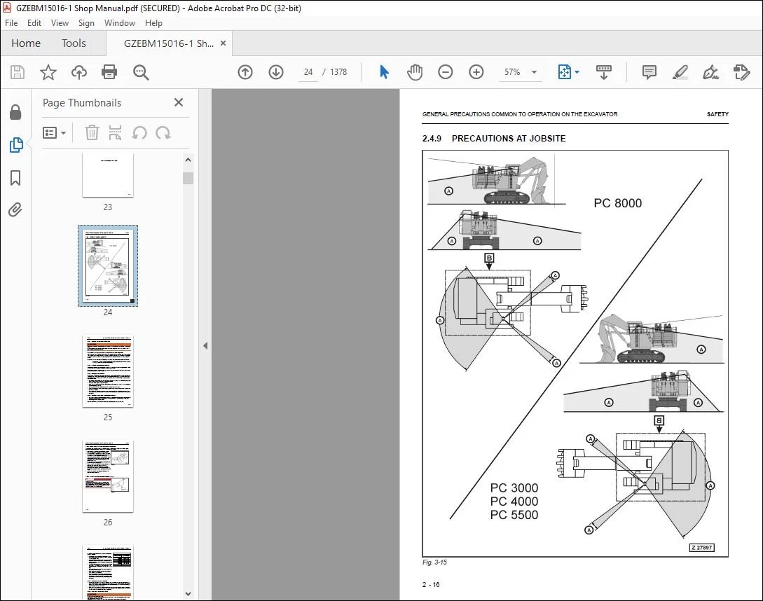
PRECAUTIONS AT JOBSITE 19
STARTING ENGINE 25
OPERATION 26
PRECAUTION FOR MAINTENANCE 32
PRECAUTIONS FOR INSPECTION AND MAINTENANCE 38
ADDITIONAL SAFETY INFORMATION FOR TROUBLESHOOTING AND ADJUSTMENTS 44
SPECIAL SAFETY EQUIPMENT 46
8 1 General layout 315
8 2 Floating function of boom and stick only FSA 319
8 3 Check and Adjustments for MRV’s and SRV’s 321
8 3 1 Check and Adjustments for MRV 323
8 3 2 Check and Adjustment for SRV’s 325
8 3 3 Check and adjustment of the throttle check valves 333
8 4 Hydraulic for the swing circuit 335
8 4 1 Hydraulic for the swing circuit 339
8 4 2 Slew gear box L & S 343
8 4 3 Slew parking brake 347
8 4 4 Slew service brake valve 351
8 4 5 Checks and adjustment of the slew pressure valve 356
8 5 Travel circuit 359
8 5 1 Rotary joint 361
8 5 2 Travel motor A2FMt 363
8 5 3 Travel gear 365
8 5 4 Travel parking brake 367
8 5 5 Travel control function 369
8 5 6 Check and Adjustment SRV travel system 372
9 TRACK TENSION SYSTEM 541
9 1 General layout 375
9 2 Track tensioning function 377
9 2 1 Cushioning 379
9 2 2 Pressure Increasing valve PIV 381
9 3 Track tensioning adjustment 385
9 3 1 Track tensioning function check 387
10 ACCESS LADDER HYDRAULICALLY OPERATED 559
10 1 Access ladder 391
10 2 Access ladder functional description 393
11 CABLE DRUM 567
11 0 1 Functional description 399
12 HINTS FOR READING THE HYDRAULIC CIRCUIT DIAGRAM 581
12 1 General 405
12 2 Symbolic 407
12 2 1 Lines, unions 408
12 2 2 Components, valves 410
12 2 3 Sensors 410
12 2 4 Valves, valve components 411
12 2 5 Pump, motor, cylinder 415
13 HINTS FOR READING THE ELECTRIC CIRCUIT DIAGRAM 598
13 1 Designation of electrical components 422
13 2 Electric symbols 423
13 3 Symbols 425
13 3 1 Drawing concept 427
13 3 2 Reading of the circuit diagram 433
14 ELECTRONIC CONTROL SYSTEM ECS 615
14 1 General Function 439
15 AUTOMATIC LUBRICATION SYSTEM 673
15 1 General Function 443
15 2 Function of a lubrication cycle 445
15 3 Lubrication pump drive 453
15 4 Lubrication pump 455
15 4 1 Adjustments lubricating pump speed 457
15 4 2 Adjustments lubricating pump pressure 459
15 5 Lubricant Injector (metering valve) 461
15 5 1 Connection of one or more injectors 463
15 5 2 Function lubrication injector (metering valve) 465
15 6 End line pressure switch 469
15 7 Lubricant in line filter 471
15 8 Lubricant level sensor 473
15 8 1 Capacitive digital type for machines with ETM 473
15 8 2 Capacitive analog type for machines with PLC 475
15 9 Lubrication system function and controlling 477
15 9 1 Central Lubrication System (CLS) function and controlling with ETM system (PC 3000) 479
15 9 2 Swing ring lubrication system (SLS) function and controlling with ETM system (PC3000) 483
15 10 Adjustment of the lubrication system with ETM 490
15 11 Trouble shooting lubricating system 491
15 11 1 Lubrication pump cylinder does not move 492
15 11 2 Lubricant pressure built up very slowly or not at all 494
15 11 3 Insufficient lubricant supply to one or more attachment bearings 494
15 11 4 Insufficient lubricant at the swing ring gear 496
40 Troubleshooting 741
Table of Contents 0
Introduction 0
Safety Notes 0
Description of this Troubleshooting Manual 0
General Precautions 0
Electrical Parts 0
Componant Locations 0
Engine Electrical Parts 0
Electrical Parts On PTO, etc 0
Electrical Parts on Pilot Control Frame 0
Electrical Parts on Main Hydraulic Reservoir 0
Electrical Parts on Switch Board X2 0
Electrical Parts on Hydraulic Ldder 0
Electrical Parts of Automatic Lube System 0
Electrical Parts on Air Cleaner and Fuel Tank 0
Overview Connector Types 0
Standard Value Table for Electrical Componants 0
PT100 Temperature Charts 0
Troubleshooting by Trouble Code 0
Message 1 – Gear Lubrication out of Function (PTO) 0
Message 2 – Engine Air Filter Restricted 0
Message 3 – Filter for Control Oil Restricted 0
Message 4 – Oil Tank Breather Filter Restricted 0
Message 5 – Return Oil Filter Restricted 0
Message 6 – Leak Oil Filter Restricted 0
Message 7 – Hydraulic Oil Temperature Too High 0
Message 9 – Low Idle Too High Coolant Temperature 0
Message 10 – Engine Shutdown: Too Low Engine Oil Temperature 0
Message 14 – Too Low Hydraulic Oil Level 0
Message 15 – Caution, Slew Gear House Brake On 0
Message 16 – Caution, Travel Gear House Brake On 0
Message 17 – No Clearance For Starting, Shift Engine to Low Idle 0
Message 18 – Central Lube System Fault 0
Message 19 – Slew Ring Gear Lubrication Fault 0
Message 20 – Pilot Control Cut-Out 0
Message 21 – Central Lube System Empty Grease Barrel 0
Message 22 – Central Lube System Empty Grease Barre 0
Message 24 – Engine Problem: Stop All Control 0
Message 32 – PTO Gear Lube Filter Restricted 0
Message 33 – Cooler Fan Drive Filter Restricted 0
Message 39 – Engine Shutdown Main Shut-Off (Gate) Volve 0
Message 42 – Too Low Coolant Pressure 0
Message 43 – Engine Shutdown: Emergency Stop Switch Actuated 0
Message 44 – Engine Shutdown Safety Switch Actuated 0
Message 45 – Warning Signal from Engine Control Module 0
Message 48 – Too High PTO Gear Oil Temperature 0
Message 50 – Caution, Pull Switch From Ground Man Actuated 0
Message 51 – Engine Shutdown: Pull Switch From Ground Man Actuated 0
Message 52 – Load Limit Clam Defective 0
Message 53 – Pressure Switch of CLS Actuated 0
Message 55 – Refill Hyrdaulic Oil 0
Message 57 – Load Limit Regulation Fault 0
Message 58 – Strainer Oil Cooler Restricted 0
Message 59 – CLS Refill Grease Container 0
Message 60 – SLS Refill Grease Barrel 0
Troubleshooting by Symptoms 0
Symptoms of the Hydraulic System 0
50 Disassembly and Assembly 743
1 INTRODUCTION 757
2 SAFETY 761
3 SUPERSTRUCTURE 793
4 UNDERCARRIAGE 1071
5 ATTACHMENT 1185
6 SERVICE INFORMATION 1361
IMAGES PREVIEW OF THE MANUAL:
Questions? Email us: [email protected]
https://vimeo.com/742145821
PLEASE NOTE:
- This is the SAME manual used by the dealers to troubleshoot any faults in your vehicle. This can be yours in 2 minutes after the payment is made.
- Contact us at [email protected] should you have any queries before your purchase or that you need any other service / repair / parts operators manual.
I.G