
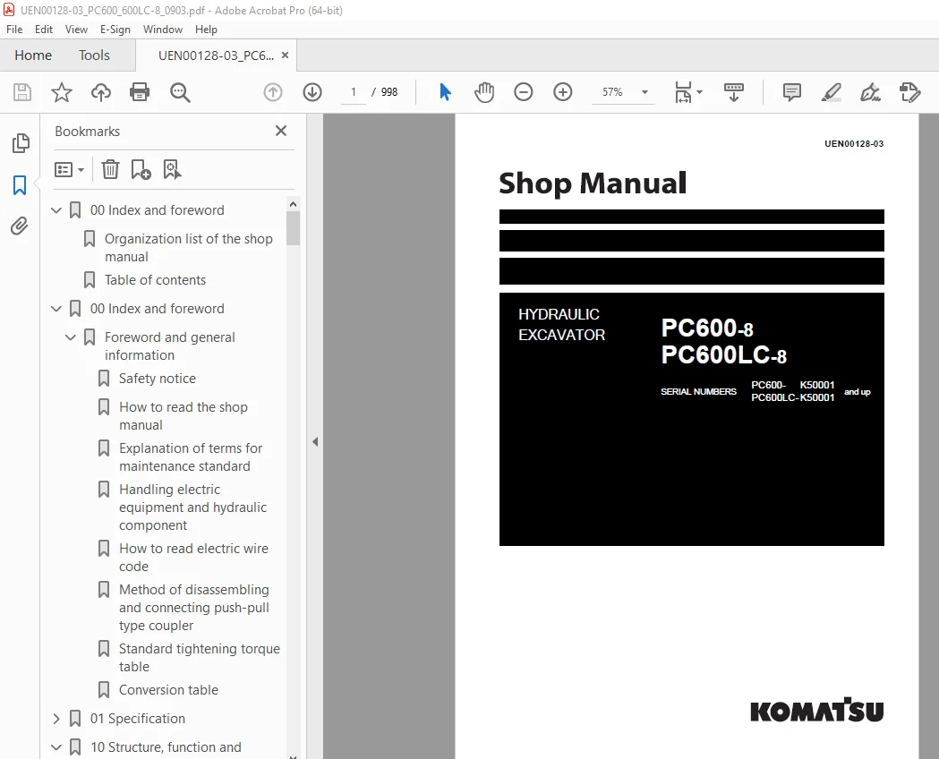

Komatsu PC600-8 PC600LC-8 Excavator Shop Manual UEN00128-03 PDF
$34.95
Komatsu PC600-8 PC600LC-8 Hydraulic Excavator Shop Manual UEN00128-03 – PDF DOWNLOAD
Description
Komatsu PC600-8 PC600LC-8 Hydraulic Excavator Shop Manual UEN00128-03 – PDF DOWNLOAD
FILE DETAILS:
Komatsu PC600-8 PC600LC-8 Hydraulic Excavator Shop Manual UEN00128-03 – PDF DOWNLOAD
Language : English
Pages : 998
Downloadable : Yes
File Type : PDF
TABLE OF CONTENTS:
Komatsu PC600-8 PC600LC-8 Hydraulic Excavator Shop Manual UEN00128-03 – PDF DOWNLOAD
00 Index and foreword 3
Organization list of the shop manual 4
Table of contents 6
00 Index and foreword 15
Foreword and general information 16
Safety notice 16
How to read the shop manual 20
Explanation of terms for maintenance standard 22
Handling electric equipment and hydraulic component 24
How to read electric wire code 32
Method of disassembling and connecting push-pull type coupler 35
Standard tightening torque table 38
Conversion table 42
01 Specification 49
Specification and technical data 50
Specification drawings 50
Working range drawings 51
Specifications 52
Weight table 58
Table of fuel, coolant and lubricants 60
10 Structure, function and maintenance standard 63
Engine and cooling system 64
Parts related to engine 64
PTO 66
Fan, control and PTO lubrication pump 68
Radiator, oil cooler 69
10 Structure, function and maintenance standard 71
Power train 72
Power train 72
Final drive 75
Sprocket 78
Swing circle 80
Swing machinery 82
10 Structure, function and maintenance standard 85
Undercarriage and frame 86
Track frame, recoil spring 86
Idler 88
Carrier roller 90
Track roller 91
Track shoe 92
10 Structure, function and maintenance standard 99
Hydraulic system, Part 1 100
Hydraulic piping drawing 100
Hydraulic tank, hydraulic filter 102
Hydraulic pump (piston pump) 104
Line oil filter 132
Cooling fan pump 134
Cooling fan motor 142
10 Structure, function and maintenance standard 149
Hydraulic system, Part 2 150
Control valve 150
Swing motor 169
Swing brake 172
Safety valve 173
Reverse prevention valve 175
Center swivel joint 178
Travel motor 179
Parking brake 184
Brake valve 186
Set pressures varying mechanism 189
Valve control 190
Work equipment, swing PPC valve 192
Travel PPC valve 196
Service PPC valve 198
PPC accumulator 199
PPC shuttle valve 200
Solenoid valve 201
Boom holding valve 206
Boom LOWER regeneration valve 210
Hydraulic drift prevention valve 214
Hydraulic cylinder 220
10 Structure, function and maintenance standard 223
Work equipment 224
Work equipment 224
Dimensions of work equpment 226
10 Structure, function and maintenance standard 231
Cab and its attachments 232
Air conditioner piping 232
10 Structure, function and maintenance standard 235
Engine control 236
Machine control system diagram 241
Monitor system 265
Sensors 280
20 Standard value table 285
Standard service value table 286
Standard value table for engine 286
Standard value table for chassis 287
30 Testing and adjusting 297
Testing and adjusting, Part 1 300
Tools for testing, adjusting and troubleshooting 300
Measuring engine speed 302
Measuring intake air pressure (boost pressure) 303
Measuring exhaust gas temperature 304
Measuring exhaust gas color 305
Adjusting valve clearance 306
Measuring compression pressure 307
Measuring blow-by pressure 309
Measuring engine oil pressure 309
Handling equipment in fuel circuit 310
Releasing remaining pressure in fuel system 310
Measuring fuel pressure 311
Reduced cylinder mode operation 312
No-injection cranking 312
Testing leakage from pressure limiter and return rate from injector 313
Bleeding air from fuel circuit 315
Testing fuel system for leakage 316
Adjusting speed sensor 317
Testing and adjusting alternator belt tension 317
Testing and adjusting air conditioner compressor belt tension 318
Testing clearance of swing circle bearing 319
Testing and adjusting track shoe tension 320
Testing and adjusting work equipment, swing, and travel circuit oil pressures 321
Testing and adjusting control circuit oil pressure 326
Testing and adjusting piston pump control oil pressure 328
Testing servo piston stroke 334
Measuring PPC valve output pressure 335
Measuring outlet pressures of solenoid valve and PPC shuttle valve 340
Adjusting work equipment, swing PPC valve 346
Testing and adjusting travel deviation 347
Measuring fan speed 349
Measuring fan circuit oil pressure 349
Inspection of locations of hydraulic drift of work equipment 350
Measuring oil leakage 351
Releasing remaining pressure in hydraulic circuit 355
Bleeding air from each part 356
Inspection procedures for diode 359
30 Testing and adjusting 361
Testing and adjusting, Part 2 362
Special function of machine monitor 362
Handling engine controller high voltage circuit 394
Preparation work for troubleshooting electrical system 395
Pm-CLINIC SERVICE 397
Pm-CLINIC SERVICE PC600, 600LC-8 402
UNDERCARRIAGE INSPECTION 403
40 Troubleshooting 405
General information on troubleshooting 406
Points to remember when troubleshooting 406
Sequence of events in troubleshooting 407
Checks before troubleshooting 408
Classification and procedures of troubleshooting 409
Connection table for connector pin numbers 413
T-boxes and T-adapters table 445
40 Troubleshooting 451
Troubleshooting by failure code (Display of code), Part 1 454
40 Troubleshooting 515
Troubleshooting by failure code (Display of code), Part 2 518
40 Troubleshooting 581
Troubleshooting by failure code (Display of code), Part 3 584
40 Troubleshooting 653
Troubleshooting of electrical system (E-mode) 656
40 Troubleshooting 713
Troubleshooting of hydraulic and mechanical system (H-mode) 715
40 Troubleshooting 755
Troubleshooting of engine (S-mode) 757
50 Disassembly and assembly 783
General information on disassembly and assembly 784
How to read this manual 784
Coating materials list 786
Special tools list 789
Sketches of special tools 795
50 Disassembly and assembly 801
Engine and cooling system, Part 1 802
Removal and installation of engine, PTO and hydraulic pump assembly 802
Removal and installation of radiator assembly 809
Removal and installation of hydraulic oil cooler assembly 811
Removal and installation of aftercooler assembly 813
Removal and installation of fan motor assembly 815
Removal and installation of fuel tank assembly 819
50 Disassembly and assembly 821
Engine and cooling system, Part 2 822
Removal and installation of fuel supply pump assembly 822
Removal and installation of cylinder head assembly 827
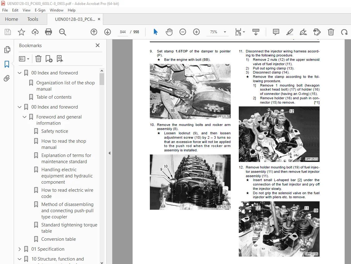
Removal and installation of fuel injector assembly 843
Removal and installation of engine front seal 846
Removal and installation of engine rear seal 848
50 Disassembly and assembly 853
Power train 854
Removal and installation of PTO assembly 854
Disassembly and assembly of PTO assembly 856
Removal and installation of swing motor and swing machinery assembly 859
Disassembly and assembly of swing machinery assembly 860
Removal and installation of swing circle assembly 867
Disassembly and assembly of final drive assembly 868
50 Disassembly and assembly 879
Undercarriage and frame 880
Removal and installation of revolving frame assembly 880
Disassembly and assembly of 1 link in field 882
Removal and installation of idler, recoil spring assembly 886
Disassembly and assembly of idler assembly 887
Disassembly and assembly of recoil spring assembly 890
Removal and installation of track roller assembly 892
Disassembly and assembly of track roller assembly 893
Removal and installation of carrier roller assembly 896
Disassembly and assembly of carrier roller assembly 897
Removal and installation of revolving frame assembly 900
Removal and installation of counterweight assembly 902
Removal and installation of counterweight remover assembly 903
50 Disassembly and assembly 907
Hydraulic system 908
Removal and installation of hydraulic tank assembly 908
Removal and installation of hydraulic pump assembly 910
Removal and installation of control valve and solenoid valve assembly 913
Disassembly and assembly of control valve assembly 915
Disassembly and assembly of main control valve assembly 916
Removal and installation of swing motor assembly 920
Removal and installation of center swivel joint assembly 921
Disassembly and assembly of center swivel joint assembly 922
Disassembly and assembly of work equipment PPC valve assembly 923
Disassembly and assembly of travel PPC valve assembly 925
Disassembly and assembly of hydraulic cylinder assembly 927
50 Disassembly and assembly 933
Work equipment 934
Removal and installation of bucket cylinder assembly 934
Removal and installation of arm cylinder assembly 936
Removal and installation of boom cylinder assembly 938
Removal and installation of bucket assembly 940
Removal and installation of arm assembly 942
Removal and installation of boom assembly 944
50 Disassembly and assembly 947
Cab and its attachments 948
Removal and installation of operator’s cab 948
Removal and installation of operator’s cab glass (stuck glass) 951
Removal and installation of front window assembly 961
50 Disassembly and assembly 967
Electrical system 968
Removal and installation of air conditioner unit assembly 968
Removal and installation of engine controller assembly 970
Removal and Installation of KOMTRAX terminal assembly 972
Removal and installation of pump controller 972
Removal and installation of monitor assembly 973
90 Diagrams and drawings 975
Hydraulic circuit diagram 977
90 Diagrams and drawings 981
Electrical circuit diagram (1/5) 983
Electrical circuit diagram (2/5) 985
Electrical circuit diagram (3/5) 987
Electrical circuit diagram (4/5) 989
Electrical circuit diagram (5/5) 991
Electrical circuit diagram for air conditioner 993
Connector arrangement diagram 995
DESCRIPTION:
Komatsu PC600-8 PC600LC-8 Hydraulic Excavator Shop Manual UEN00128-03 – PDF DOWNLOAD
1. Composition of shop manual
This shop manual contains the necessary technical information for services performed in a workshop.
For ease of understanding, the manual is divided into the following sections.
This section explains the shop manuals list, table of contents, safety, and basic information.
01. Specification
This section explains the specifications of the machine.
10. Structure, function and maintenance standard
This section explains the structure, function, and maintenance standard values of each component.
The structure and function sub-section explains the structure and function of each component. It
serves not only to give an understanding of the structure, but also serves as reference material
for troubleshooting. The maintenance standard sub-section explains the criteria and remedies for
dis- assembly and service.
This section explains the standard values for new machine and judgement criteria for testing,
adjusting, and troubleshooting. This standard value table is used to check the standard values in
testing and adjusting and to judge parts in troubleshooting.
This section explains measuring instruments and measuring methods for testing and adjusting, and
method of adjusting each part. The standard values and judgement criteria for testing and adjusting
are explained in Testing and adjusting.
This section explains how to find out failed parts and how to repair them. The troubleshooting is
divided by failure modes. The “S mode” of the troubleshooting related to the engine may be also
explained in the Chassis volume and Engine volume. In this case, see the Chassis volume.
This section explains the special tools and procedures for removing, installing, disassembling, and
assembling each component, as well as precautions for them. In addition, tightening torque and
quantity and weight of coating material, oil, grease, and coolant necessary for the work are also
explained.
• Chassis volume
This section gives hydraulic circuit diagrams and electrical circuit diagrams.
• Engine volume
This section explains the method of reproducing, repairing, and replacing parts.
IMAGES PREVIEW OF THE MANUAL:
S.V 28/12/24



