
Trusted Business
Verified & Licensed
Virus Free Files
100% Safe Downloads
Secure Payment
SSL Protected
Instant Delivery
Available Immediately
Sale!


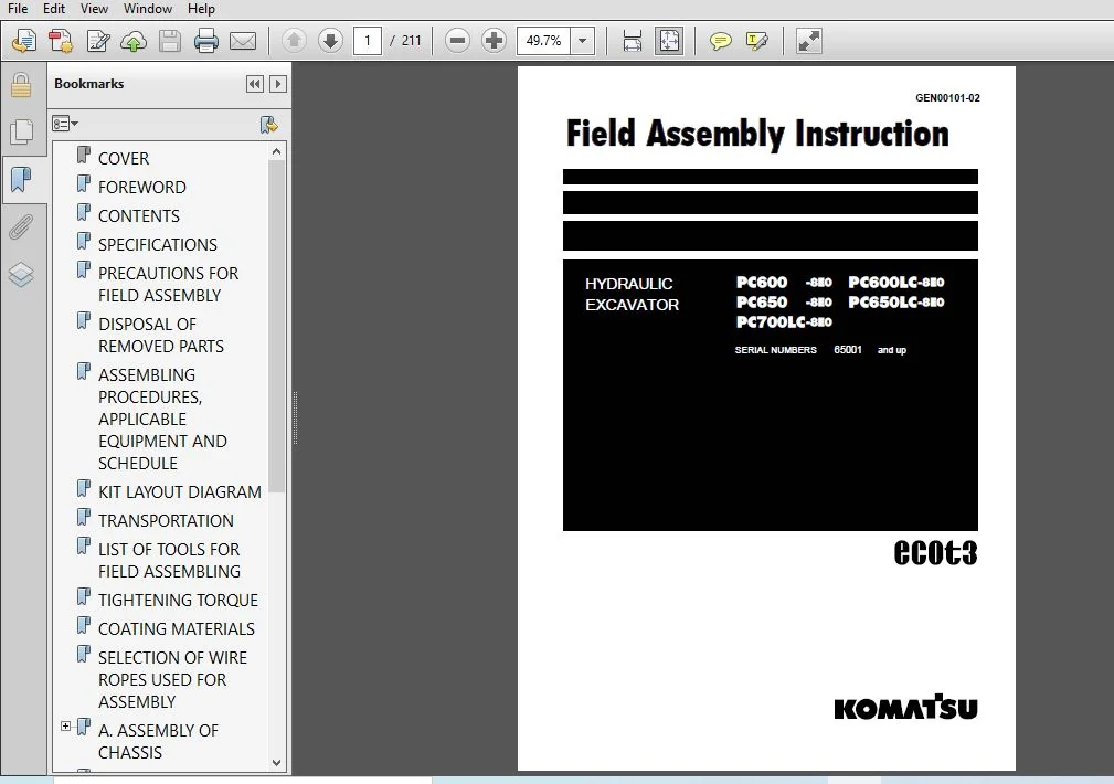
KOMATSU PC600-8E0 PC600LC-8E0 PC650-8E0 PC650LC-8E0 PC700LC-8E0 HYDRAULIC EXCAVATOR Field Assembly Instruction MANUAL (SN:65001 & UP) – PDF DOWNLOAD
Original price was: $73.95.$26.95Current price is: $26.95.
- KOMATSU PC600-8E0 PC600LC-8E0 PC650-8E0 PC650LC-8E0 PC700LC-8E0 HYDRAULIC EXCAVATOR Field Assembly Instruction MANUAL
- SERIAL NUMBER:65001 & UP
- PUBLICATION NUMBER:GEN00101-02
Instant PDF Download
Available immediately
Save to Your Device
Download & keep forever
Antivirus Scanned
100% virus-free
Trusted Worldwide
175,000+ customers
Description
KOMATSU PC600-8E0 PC600LC-8E0 PC650-8E0 PC650LC-8E0 PC700LC-8E0 HYDRAULIC EXCAVATOR Field Assembly Instruction MANUAL (SN:65001 & UP)
KOMATSU PC600-8E0 PC600LC-8E0 PC650-8E0 PC650LC-8E0 PC700LC-8E0 HYDRAULIC EXCAVATOR FIELD ASSEMBLY INSTRUCTION MANUAL (SN:65001 & UP) – PDF DOWNLOAD:
IMAGE PREVIEW:
SAMPLE PAGE FROM THE MANUAL:
KOMATSU PC600-8E0 PC600LC-8E0 PC650-8E0 PC650LC-8E0 PC700LC-8E0 HYDRAULIC EXCAVATOR Field Assembly Instruction MANUAL (SN:65001 & UP)
- Since this machine is large in size, it is divided into some units to meet the transportation conditions and regulations applied to the transportation route when shipped from our factory. This manual describes how to assemble the units into the complete machine in the field. We hope that this machine will display its quality and you will use it safely according to the operation manual.
- Many units are large in size and heavy in weight and may be handled in a dangerous place or posture and many workers may have to work together to sling them with cranes. Accordingly, before starting the assembly work, the work supervisor is required to hold a safety meeting to oblige the workers to put on protective gear and appoint a work leader and a crane work signal man and allot roles to all the workers for safe work.
- In particular, the above meeting is more important when worker of different languages and customs work together. The following is a reference supervision system diagram. When the work equipment is installed, the engine must be operated.
- Accordingly, before installing the work equipment, inspect and maintain the machine thoroughly. Note that this manual does not describe the whole specification of the machine but describes only the basic specification. If you have any question when dividing and transporting the machine by yourself in future, ask one of our distributors
TABLE OF CONTENTS:
KOMATSU PC600-8E0 PC600LC-8E0 PC650-8E0 PC650LC-8E0 PC700LC-8E0 HYDRAULIC EXCAVATOR Field Assembly Instruction MANUAL (SN:65001 & UP)
COVER
..............................................................................  1
FOREWORD............................................................................  2
CONTENTS............................................................................  3
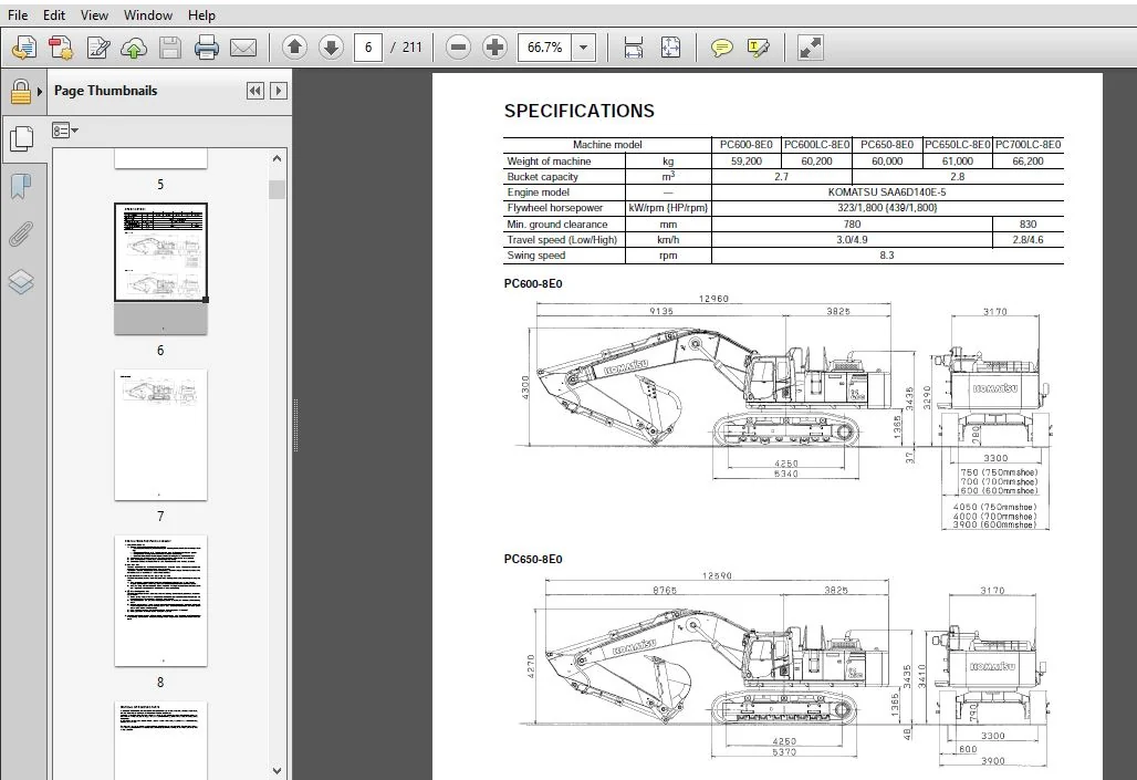
SPECIFICATIONS......................................................................  6
PRECAUTIONS FOR FIELD ASSEMBLY......................................................  8
DISPOSAL OF REMOVED PARTS...........................................................  9
ASSEMBLING PROCEDURES, APPLICABLE EQUIPMENT AND SCHEDULE............................ 10
KIT LAYOUT DIAGRAM.................................................................. 11
TRANSPORTATION...................................................................... 12
LIST OF TOOLS FOR FIELD ASSEMBLING.................................................. 17
TIGHTENING TORQUE................................................................... 18
COATING MATERIALS................................................................... 23
SELECTION OF WIRE ROPES USED FOR ASSEMBLY........................................... 25
A. ASSEMBLY OF CHASSIS.............................................................. 26
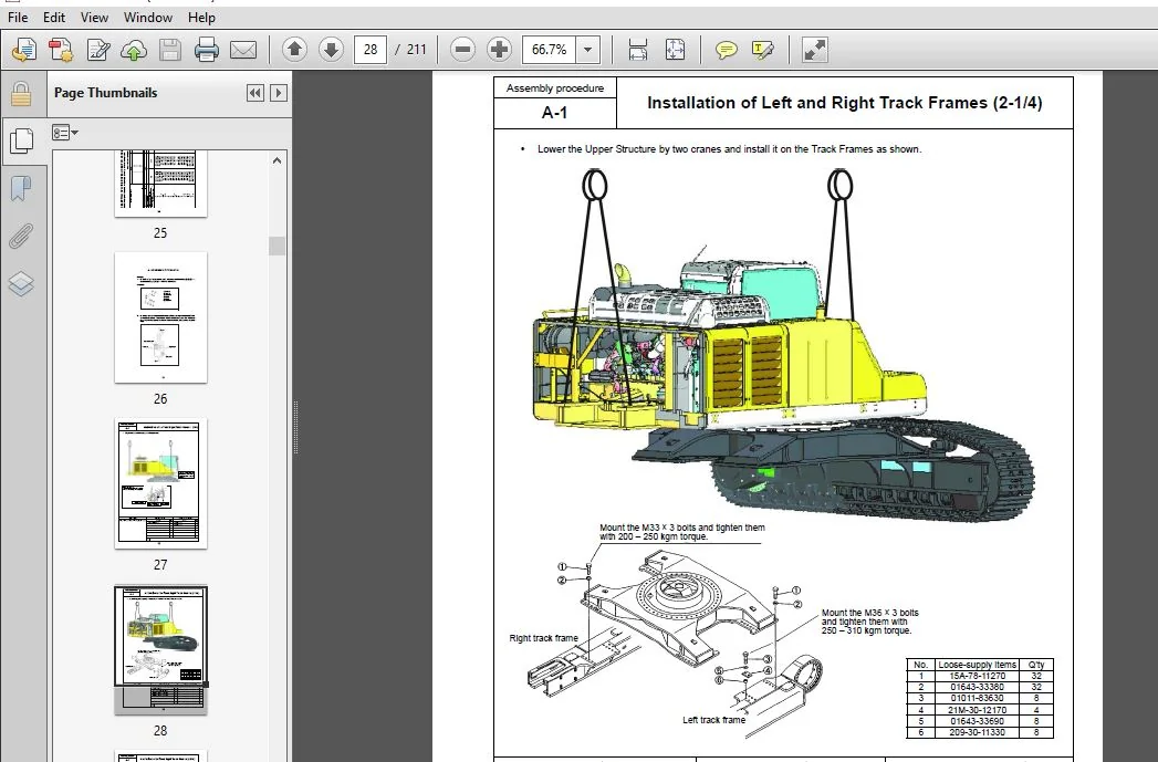
	A- 1. Installation of Left and Right Track Frames............................... 27
	A- 2. Installation of Travel Pipe............................................... 32
	A- 3. Installation of Operator Cab’s Left Handrail.............................. 37
	A- 4. Installation of Operator Cab’s Door Stopper and Striker................... 38
	A- 5. Installation of Rearview Mirror........................................... 40
	A- 6. Installation of Handrail.................................................. 45
	A- 7-1 Installation of Step..................................................... 48
	A- 7-2 Installation of Step..................................................... 49
	A- 8. Installation of Left Side Step............................................ 50
	A- 9. Sticking Sheet to Counterweight........................................... 51
	A-10. Installation of Rear View Camera.......................................... 52
	A-11. Installation of Counterweight............................................. 57
	A-12. Installation of Step Light................................................ 59
	A-13. Bleeding of Air from Travel Motor......................................... 61
	A-14-1 Installation of Travel Piping Cover...................................... 62
	A-14-2 Installation of Travel Piping Cover...................................... 66
	A-15. Installation of Travel Motor Guard........................................ 69
	A-16. Testing Track Shoe Tension................................................ 70
	A-17. Check Fuel, Coolant and Oil Levels........................................ 73
B. ASSEMBLING OF WORK EQUIPMENT..................................................... 76
	B- 1. Assembly of Arm Cylinder.................................................. 77
	B- 2. Connection of Arm Cylinder Hoses.......................................... 78
	B- 3. Installation of Boom Cylinder............................................. 79
	B- 4. Installation of Boom Cylinder Hoses....................................... 80
	B- 5. Installation of Boom Foot Dust Seal....................................... 81
	B- 6. Assembly of Boom Assembly................................................. 82
	B- 7. Installation of Hoses from Chassis Along Top of Boom...................... 83
	B- 8. Connection of Boom Cylinder Head.......................................... 85
	B- 9. Installation of Arm Assembly.............................................. 86
	B-10. Installation of Bucket Cylinder Hoses between Boom and Bucket Cylinder.... 88
	B-11. Installation of Bucket.................................................... 89
	B-12. Connection of Work Equipment Grease Piping................................ 92
	B-13. Connection of Work Equipment Wiring....................................... 93
	B-14. Greasing after Assembling Work Equipment.................................. 95
	B-15. Bleeding Air from Work Equipment Circuit.................................. 96
	B-16. Parts to be Touched up After Field Assembly............................... 97
C. Assembling of Work Equipment of Loading Shovel................................... 98
	C- 1. Releasing residual pressure in hydraulic circuit.......................... 99
	C- 2. Pulling out boom foot pin and boom cylinder foot pin......................100
	C- 3. Installation of boom cylinder foot........................................101
	C- 4. Installation of boom and arm assembly.....................................102
	C- 5. Installation of boom cylinder hoses.......................................103
	C- 6. Installation of boom cylinder rod pin.....................................104
	C- 7. Installation of boom cylinder.............................................105
	C- 8. Installation of arm cylinder hoses........................................106
	C- 9. Installation of bucket cylinder...........................................107
	C-10. Installation of bucket cylinder hoses.....................................108
	C-11. Installation of connecting hoses between chassis and boom top.............109
	C-12. Installation of bottom dump cylinder hoses................................110
	C-13. Installation of bucket assembly...........................................111
	C-14. Installation of working lamps.............................................113
	C-15. Installation of work equipment grease piping..............................115
	C-16. Greasing after assembling of work equipment...............................116
	C-17. Bleeding air from work equipment circuit..................................117
	C-18. Checking oil level in hydraulic tank and adding oil.......................118
D. ASSEMBLING OF COUNTERWEIGHT REMOVER..............................................120
	D- 1. Sticking Sheet to Counterweight...........................................121
	D- 2. Adjustment of Shims for Counterweight.....................................122
	D- 3. Greasing..................................................................127
	D- 4. Installation of Counterweight Remover.....................................128
	D- 5. Installation of Covers....................................................129
	D- 6. Installation of Clamps....................................................130
	D- 7. Installation of Hoses.....................................................133
	D- 8. Bleeding Air from Counterweight Remover Circuit...........................134
	D- 9. Installation of Counterweight.............................................135
	D-10. Installation of Accessories...............................................137
	D-11. Check of Operation........................................................138
M. PROCEDURE FOR INSPECTION AND MAINTENANCE AFTER COMPLETION OF ASSEMBLY............140
	M- 1. Inspection of Oil Level in Hydraulic Tank and Refill......................141
	M- 2. Replacement of Return Filter (Standard Filter to Flushing Filter).........143
	M- 3. Flushing of Hydraulic Circuit.............................................146
	M- 4. Failure code..............................................................148
	M- 5. Operating Method of ......................................................153
Field Assembly Inspection Report (Backhoe)..........................................160
Field Assembly Inspection Report (Loading Shovel)...................................186
PLEASE NOTE:
⦁ This is the same manual used by the DEALERSHIPS to SERVICE your vehicle.
⦁ The manual can be all yours – Once payment is complete, you will be taken to the download page from where you can download the manual. All in 2-5 minutes time!!
⦁ Need any other service / repair / parts manual, please feel free to contact us at heydownloadss @gmail.com . We may surprise you with a nice offer



