
Komatsu PC70-8 Hydraulic Excavator Shop Manual SEN06204-02 PDF
$36.95
Komatsu PC70-8 Hydraulic Excavator Shop Manual SEN06204-02 – PDF DOWNLOAD
- SERIAL NUMBERS 10011 and up
Description
Komatsu PC70-8 Hydraulic Excavator Shop Manual SEN06204-02 – PDF DOWNLOAD
FILE DETAILS:
Komatsu PC70-8 Hydraulic Excavator Shop Manual SEN06204-02 – PDF DOWNLOAD
Language : English
Pages : 1134
Downloadable : Yes
File Type : PDF
IMAGES PREVIEW OF THE MANUAL:
TABLE OF CONTENTS:
Komatsu PC70-8 Hydraulic Excavator Shop Manual SEN06204-02 – PDF DOWNLOAD
- SERIAL NUMBERS 10011 and up
Cover . 1
00 Index and foreword . 3
100 Index . 3
Composition of shop manual 4
Table of contents . 6
200 Foreword and general information 17
Foreword, safety and general information 18
How to read the shop manual . 25
Explanation of terms for maintenance standard . 27
Handling equipment of fuel system devices . 29
Handling of intake system parts . 30
Handling of hydraulic equipment . 31
Method of disconnecting and connecting of push-pull type coupler 33
Handling of electrical equipment 36
How to read electric wire code 45
Precautions when performing operation . 48
Practical use of KOMTRAX 51
Standard tightening torque table 52
List of abbreviation 56
Conversion table 61
01 Specification 67
100 Specification and technical data 67
Specification drawing . 68
Working range drawings 69
Specification . 70
Weight table 74
Table of fuel, coolant, and lubricants 76
10 Structure, function and maintenance standard . 79
100 Engine and cooling system . 79
Engine mount 80
PTO . 81
Cooling system 82
200 Power train . 85
Power train system 86
Swing circle 88
Swing machinery . 90
300 Undercarriage and frame . 93
Track frame . 94
Idler cushion . 95
Idler . 96
Track roller 97
Carrier roller 98
Sprocket 99
Track shoe 100
401 Hydraulic system, Part 1 105
Hydraulic component layout 106
Valve control . 108
Hydraulic tank 109
Hydraulic tank 111
CLSS 113
Main pump . 116
402 Hydraulic system, Part 2 135
Control valve . 136
Each function and operation by valve 148
403 Hydraulic system, Part 3 183
Swing motor . 185
Travel motor 195
PPC valve . 203
Solenoid valve 218
Center swivel joint . 221
Accumulator . 223
500 Work equipment 225
Work equipment 226
Dimensions of work equipment 228
Work equipment cylinder . 232
600 Electrical system . 235
Electrical control system . 236
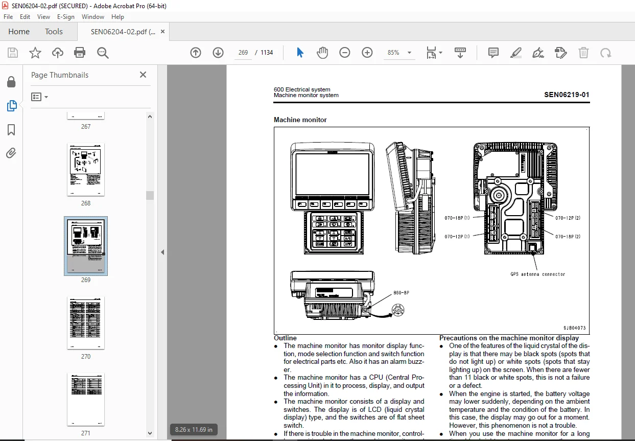
Machine monitor system 268
KOMTRAX system 282
Sensors . 286
20 Standard value table . 293
100 Standard service value table 293
Standard value table for engine . 294
Standard value table for machine 295
30 Testing and adjusting 307
101 Testing and adjusting, Part 1 . 307
Tools for testing, adjusting, and troubleshooting . 309
Testing engine speed 314
Testing exhaust gas color . 315
Testing exhaust gas temperature . 316
Adjusting valve clearance . 317
Testing compression pressure 319
Testing blowby pressure . 322
Testing engine oil pressure . 323
Handling equipment of fuel system devices . 324
Releasing remaining pressure from fuel system . 324
Testing fuel pressure . 325
Testing fuel return rate and leakage 326
Bleeding air from fuel circuit 328
Testing fuel circuit for leakage 330
Handling cylinder cutout mode operation . 330
Handling No-injection cranking operation 331
Testing and adjusting fan belt tension 332
Testing and adjusting air conditioner compressor belt tension . 334
Testing swing circle bearing clearance 335
Testing and adjusting track tension . 336
Testing and adjusting oil pressure in work equipment and travel circuits 337
Testing and adjusting oil pressure in swing and blade circuits (blade specification) 339
Testing source pressure of control circuit 342
Testing and adjusting oil pressure in pump PC control circuit . 343
Testing LS differential pressure and adjusting LS valve . 347
Testing solenoid valve output pressure 349
Testing PPC valve output pressure . 351
Adjusting play of work equipment and swing PPC valves . 353
Isolating parts causing hydraulic drift in work equipment . 354
Testing and adjusting travel deviation 355
Releasing remaining pressure in hydraulic circuit . 357
Testing oil leakage . 358
Bleeding air from each part . 361
Adjusting mirror 363
Testing and adjusting hood catcher 364
102 Testing and adjusting, Part 2 . 367
Special functions of machine monitor 368
103 Testing and adjusting, Part 3 . 417
Handling voltage circuit of engine controller . 418
Preparation for troubleshooting of electrical system 419
Handling battery disconnect switch 423
Testing diodes 424
Pm Clinic service . 425
40 Troubleshooting 431
100 Failure code table and fuse locations . 431
Failure codes table . 432
Fuse locations 436
200 Related information on troubleshooting 439
Troubleshooting points 440
Sequence of events in troubleshooting . 441
Checks before troubleshooting . 443
Classification and procedures for troubleshooting . 444
Symptom of failures and troubleshooting numbers . 447
Information described in troubleshooting table 450
Connection table for connector pin numbers 452
T-box and T-adapter table . 488
Procedure for troubleshooting wiring harness of pressure sensor system for open circuit . 492
301 Troubleshooting by failure code, Part 1 . 497
Failure code [989L00] Engine Controller Lock Caution 1 499
Failure code [989M00] Engine Controller Lock Caution 2 500
Failure code [989N00] Engine Controller Lock Caution 3 501
Failure code [AA10NX] Air Cleaner Clogging 502
Failure code [AB00KE] Charge Voltage Low 504
Failure code [B@BAZG] Eng Oil Press Low . 506
Failure code [B@BCNS] Eng Water Overheat 507
Failure code [B@HANS] Hyd Oil Overheat 508
Failure code [CA111] ECM Critical Internal Failure 509
Failure code [CA115] Eng Ne and Bkup Speed Sens Error . 510
Failure code [CA122] Chg Air Press Sensor High Error 512
Failure code [CA123] Chg Air Press Sensor Low Error . 514
Failure code [CA131] Throttle Sensor High Error . 516
Failure code [CA132] Throttle Sensor Low Error 518
Failure code [CA144] Coolant Temp Sens High Error . 520
Failure code [CA145] Coolant Temp Sens Low Error 522
Failure code [CA153] Chg Air Temp Sensor High Error . 524
Failure code [CA154] Chg Air Temp Sensor Low Error 526
Failure code [CA187] Sensor 2 Supply Volt Low Error . 528
Failure code [CA221] Ambient Press Sensor High Error 530
Failure code [CA222] Ambient Press Sens Low Error . 532
Failure code [CA227] Sensor 2 Supply Volt High Error 534
Failure code [CA234] Eng Overspeed 534
Failure code [CA238] Ne Speed Sensor Supply Volt Error 535
Failure code [CA271] IMV/PCV1 Short Error . 536
Failure code [CA272] IMV/PCV1 Open Error 537
Failure code [CA322] Inj #1(L#1) Open/Short Error . 538
Failure code [CA324] Inj #3(L#3) Open/Short Error . 540
Failure code [CA331] Inj #2(L#2) Open/Short Error . 542
Failure code [CA332] Inj #4(L#4) Open/Short Error . 544
Failure code [CA351] Injectors Drive Circuit Error 546
302 Troubleshooting by failure code, Part 2 . 549
Failure code [CA352] Sensor 1 Supply Volt Low Error . 550
Failure code [CA386] Sensor 1 Supply Volt High Error 552
Failure code [CA428] Water in Fuel Sensor High Error 554
Failure code [CA429] Water in Fuel Sensor Low Error . 556
Failure code [CA435] Eng Oil Press Sw Error . 559
Failure code [CA441] Battery Voltage Low Error 560
Failure code [CA442] Battery Voltage High Error . 564
Failure code [CA449] Rail Press Very High Error . 565
Failure code [CA451] Rail Press Sensor High Error . 566
Failure code [CA452] Rail Press Sensor Low Error 568
Failure code [CA553] Rail Press High Error 570
Failure code [CA559] Rail Press Low Error . 571
Failure code [CA689] Eng Ne Speed Sensor Error 574
Failure code [CA731] Eng Bkup Speed Sens Phase Error 576
Failure code [CA757] All Continuous Data Lost Error . 577
Failure code [CA778] Eng Bkup Speed Sensor Error 578
Failure code [CA1633] KOMNET Datalink Timeout Error . 581
Failure code [CA2185] Throt Sensor Sup Volt High Error 582
Failure code [CA2186] Throt Sensor Sup Volt Low Error . 583
Failure code [CA2249] Rail Press Very Low Error . 584
Failure code [CA2311] IMV Solenoid Error 585
303 Troubleshooting by failure code, Part 3 . 587
Failure code [D110KB] Battery Relay Drive Short Circuit . 588
Failure code [D19JKZ] Personal Code Relay Abnormality . 590
Failure code [D862KA] GPS Antenna Open Circuit 593
Failure code [DA22KK] Pump Solenoid Power Low Error . 594
Failure code [DA25KP] 5 V Sensor 1 Power Abnormality 596
Failure code [DA25KP] 5 V Sensor 1 Power Abnormality (Machines equipped with large capacity prefilter) 598
Failure code [DA29KQ] Model Selection Abnormality . 600
Failure code [DA2RMC] CAN Discon (Pump Con Detected) 602
Failure code [DAFGMC] GPS Module Error 608
Failure code [DAFRMC] CAN Discon (Monitor Detected) . 609
Failure code [DGH2KB] Hyd Oil Sensor Short Circuit 614
Failure code [DHPAMA] Pump Press Sensor Abnormality . 616
Failure code [DHS5KX] Travel PPC Press Sensor Abnormality . 618
Failure code [DHSAMA] Swing RH PPC Press Sensor Abnormality . 620
Failure code [DHSBMA] Swing LH PPC Press Sensor Abnormality . 622
Failure code [DV20KB] Travel Alarm Short Circuit 624
304 Troubleshooting by failure code, Part 4 . 627
Failure code [DW43KA] Travel Speed Sol Open Circuit . 628
Failure code [DW43KB] Travel Speed Sol Short Circuit 630
Failure code [DW45KA] Swing Brake Sol Open Circuit 632
Failure code [DW45KB] Swing Brake Sol Short Circuit . 634
Failure code [DWJ0KA] Merge-divider Sol Open Circuit 638
Failure code [DWJ0KB] Merge-divider Sol Short Circuit . 640
Failure code [DXA8KA] PC-EPC Sol Open Circuit . 642
Failure code [DXA8KB] PC-EPC Sol Short Circuit 644
Failure code [DY20KA] Wiper Working Abnormality . 646
Failure code [DY20MA] Wiper Parking Abnormality . 648
Failure code [DY2CKB] Washer Drive Short Circuit 650
Failure code [DY2DKB] Wiper Drive (Fwd) Short Circuit . 652
Failure code [DY2EKB] Wiper Drive (Rev) Short Circuit . 654
400 Troubleshooting of electrical system (E-mode) . 657
Fuse locations 660
Information described in troubleshooting table 662
E-1 Engine does not start (Engine does not crank) . 665
E-2 Preheater does not operate 670
E-3 When starting switch is turned to ON position, machine monitor displays nothing . 673
E-4 Precaution monitor lights up while engine is running 676
E-5 Emergency stop monitor lights up while engine is running 678
E-6 Fuel level gauge does not indicate correct level 679
E-7 Engine coolant temperature gauge does not indicate correct temperature 681
E-8 Hydraulic oil temperature gauge does not indicate correct temperature . 682
E-9 Displays on machine monitor are different from those for actual machine . 685
E-10 Some areas of machine monitor screen are not displayed . 686
E-11Function switch does not work . 686
E-12 Automatic warm-up system does not operate (in cold season) . 687
E-13 Auto-decelerator does not operate properly . 688
E-14 Working mode does not change . 689
E-15 Travel speed does not change . 690
E-16 Alarm buzzer does not stop sounding 691
E-17 Service meter is not displayed, while starting switch is in OFF position . 691
E-18 Service mode cannot be selected 691
E-19 All work equipment, and swing and travel system do not operate, or cannot be locked 692
E-20 Swing parking brake does not operate properly 694
E-21 Horn does not sound or does not stop sounding 698
E-22 Windshield wiper and window washer do not operate 700
E-23 “BOOM LOWER” indicator is not displayed properly with monitoring function 702
E-24 “Arm OUT” is not displayed properly with monitoring function . 704
E-25 “ARM IN” indicator is not displayed properly with monitoring function 706
E-26 Boom RAISE ON is not displayed correctly with monitoring function 708
E-27 “Bucket CURL” is not displayed correctly with monitoring function 710
E-28 “Bucket DUMP” is not displayed correctly with monitoring function 712
E-29 “Blade RAISE” is not displayed correctly with monitoring function 714
E-30 “Blade LOWER” operation is not displayed normally by monitoring function . 716
E-31 “Swing” is not displayed correctly with monitoring function 718
E-32 “Travel” indicator is not displayed properly with monitoring function 718
E-33 “Service” is not displayed normally by monitoring function . 720
E-34 KOMTRAX system does not operate properly . 722
500 Troubleshooting of hydraulic and mechanical system (H-mode) . 725
Information described in troubleshooting table (H mode) . 727
System chart of hydraulic and mechanical systems 728
H-1 All of work equipments, swing and travel operations lack speed or power . 732
H-2 Engine speed drops largely or engine stalls . 733
H-3 Any of work equipment, swing and travel does not work . 734
H-4 Unusual noise is heard from around hydraulic pump . 734
H-5 Fine control performance or response of work equipment and travel is poor . 735
H-6 Boom speed or power is low 736
H-7 Arm speed or power is low . 737
H-8 Bucket speed or power is low 738
H-9 Blade speed or power is low . 739
H-10 Work equipment does not move in single operation . 740
H-11 Hydraulic drift of work equipment is large . 741
H-12 Time lag of work equipment is large 743
H-13 In combined operation of work equipment, equipment having heavier load moves slower 744
H-14 Boom RAISE speed is low in combined operation of swing and boom RAISE 744
H-15 In combined operation of swing and travel, travel speed drops largely 745
H-16 Machine does not travel straight . 746
H-17 Travel speed is slow . 747
H-18 Machine is hard to steer or travel power is low 748
H-19 Travel speed does not change, or travel speed is too slow or fast 749
H-20 One of tracks does not run . 749
H-21 Upper structure does not swing . 750
H-22 Swing acceleration or swing speed is low, or swing power is low 751
H-23 Upper structure overruns excessively when it stops swinging 752
H-24 Shock is large when upper structure stops swinging . 753
H-25 Large unusual noise is heard when upper structure stops swinging . 753
H-26 Swing drift on a slope is large 754
600 Troubleshooting of engine (S-mode) 757
Method of using troubleshooting chart . 758
S-1 Starting performance is poor 762
S-2 Engine does not start . 763
S-3 Engine does not pick up smoothly 766
S-4 Engine stops during operations 767
S-5 Engine does not rotate smoothly . 768
S-6 Engine lacks output (or lacks power) 769
S-7 Exhaust smoke is black (incomplete combustion) 770
S-8 Oil consumption is excessive (or exhaust smoke is blue) . 771
S-9 Oil becomes contaminated quickly 772
S-10 Fuel consumption is excessive 773
S-11 Oil is in coolant (or coolant spurts back or coolant level goes down) 774
S-12 Oil pressure drops . 775
S-13 Oil level rises (Entry of coolant or fuel) . 776
S-14 Coolant temperature becomes too high (overheating) . 777
S-15 Abnormal noise is made . 778
S-16 Vibration is excessive . 779
50 Disassembly and assembly . 781
100 General information on disassembly and assembly . 781
How to read this manual . 782
Coating materials list 783
Special tools list 787
Sketches of special tools . 790
200 Engine and cooling system . 797
Removal and installation of fuel injector assembly 798
Removal and installation of fuel supply pump assembly . 802
Removal and installation of engine front oil seal . 806
Removal and installation of engine rear oil seal 808
Removal and installation of cylinder head assembly 810
Removal and installation of cylinder head assembly (precleaner specification) . 820
Removal and installation of radiator assembly . 830
Removal and installation of aftercooler assembly 832
Removal and installation of aftercooler assembly (precleaner specification) . 835
Removal and installation of work equipment oil cooler assembly 838
Removal and installation of work equipment oil cooler assembly (precleaner specification) . 842
Removal and installation of engine and hydraulic pump assembly 846
Removal and installation of engine and hydraulic pump assembly (precleaner specification) . 854
Removal and installation of engine hood assembly 863
Removal and installation of fuel tank assembly 864
300 Power train . 867
Removal and installation of travel motor and final drive assembly . 868
Disassembly and assembly of travel motor and final drive assembly . 870
Removal and installation of swing motor and swing machinery assembly 908
Disassembly and assembly of swing machinery assembly 910
Removal and installation of swing circle assembly . 917
400 Undercarriage and frame . 919
Separation and connection of track shoe assembly 920
Removal and installation of idler and recoil spring assembly 922
Removal and installation of track roller assembly . 923
Removal and installation of carrier roller assembly . 924
Disassembly and assembly of idler assembly 925
Disassembly and assembly of recoil spring assembly 928
Disassembly and assembly of track roller assembly . 930
Removal and installation of sprocket 933
Removal and installation of revolving frame assembly 934
Removal and installation of counterweight assembly 936
500 Hydraulic system 941
Removal and installation of center swivel joint assembly 942
Disassembly and assembly of center swivel joint assembly 944
Removal and installation of hydraulic tank assembly . 946
Removal and installation of hydraulic pump assembly . 949
Removal and installation of control valve assembly 953
Disassembly and assembly of control valve . 957
Disassembly and assembly of work equipment PPC valve assembly . 960
Disassembly and assembly of travel PPC valve assembly . 961
Disassembly and assembly of hydraulic cylinder assembly . 963
600 Work equipment 969
Removal and installation of work equipment assembly . 970
Removal and installation of blade assembly 973
700 Cab and its attachments . 977
Removal and installation of operator’s cab assembly . 978
Removal and installation of operator’s cab glass (adhered window glass) . 986
Removal and installation of front window assembly . 995
Removal and installation of air conditioner compressor assembly . 996
Removal and installation of air conditioner condenser assembly 998
Removal and installation of air conditioner unit assembly . 999
800 Electrical system .1003
Removal and installation of machine monitor assembly 1004
Removal and installation of engine controller assembly 1006
Removal and installation of pump controller assembly 1008
Removal and installation of KOMTRAX terminal assembly .1009
80 Appendix .1011
100 Air conditioner .1011
Precautions for refrigerant .1013
Air conditioner component .1014
Configuration and function of refrigeration cycle .1016
Outline of refrigeration cycle 1017
Air conditioner unit 1019
Air conditioner controller 1024
Compressor 1025
Condenser .1026
Receiver drier 1027
Sunlight sensor .1028
Procedure for testing and troubleshooting .1029
System diagram 1032
Circuit diagram and arrangement of connector pins .1035
Parts and connectors layout .1038
Testing air leakage (duct) 1042
Testing with self-diagnosis function 1043
Teating temperature control .1046
Testing vent (mode) changeover 1048
Testing Recirc/Fresh changeover .1050
Checking evaporator temperature sensor 1052
Testing relays 1053
Troubleshooting chart 1 .1054
Troubleshooting chart 2 .1056
Information in troubleshooting table 1058
Troubleshooting for power supply and CAN communication system (Air conditioner does not operate) 1059
Troubleshooting for compressor and refrigerant system (Air is not cooled) .1062
Troubleshooting for blower motor system (No air comes out or air flow is abnormal) 1065
Troubleshooting for temperature control .1068
Troubleshooting for vent (mode) changeover 1070
Troubleshooting for FRESH/RECIRC air changeover .1072
Troubleshooting for evaporator temperature sensor .1074
Troubleshooting for inside air temperature sensor .1076
Troubleshooting for sunlight sensor .1078
Troubleshooting with gauge pressure .1080
Connection of service tool 1082
Precautions for disconnecting and connecting air conditioner piping .1083
Handling of compressor oil 1085
90 Diagrams and drawings 1089
100 Hydraulic diagrams and drawings .1089
Symbols in hydraulic circuit diagram 1090
Hydraulic circuit diagram .1093
200 Electrical diagrams and drawings 1099
Symbols in electric circuit diagram .1100
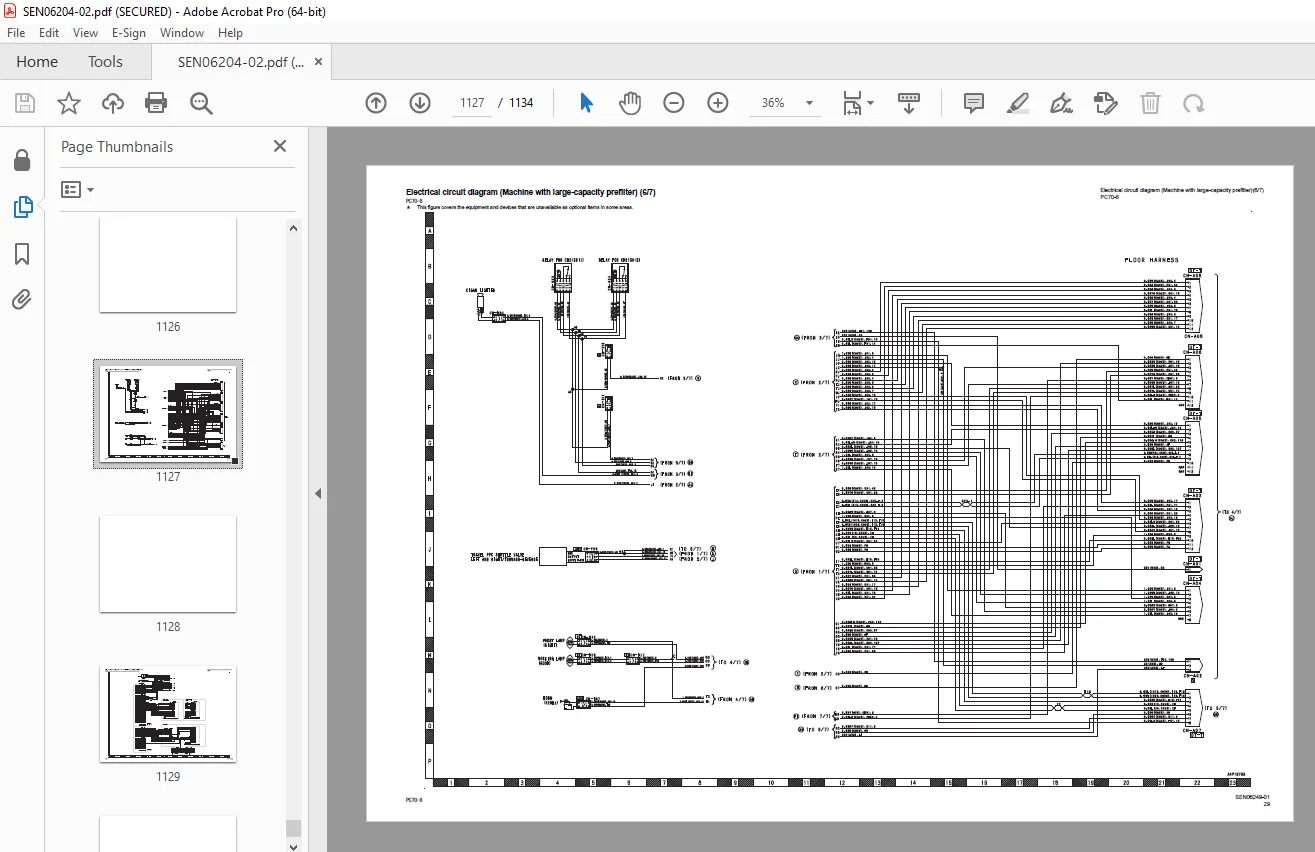
Electrical circuit diagram 1103
Air conditioner electrical circuit diagram 1131
DESCRIPTION:
Komatsu PC70-8 Hydraulic Excavator Shop Manual SEN06204-02 – PDF DOWNLOAD
- SERIAL NUMBERS 10011 and up
- GENERAL PRECAUTIONS:
- Before performing any greasing or repairs, read all the safety labels stuck to the machine. For the locations of the safety labels and detailed explanation of precautions, see the operation and maintenance manual.
- Locate a place in the repair workshop to keep the tools and removed parts. Always keep the tools and parts in their correct places. Always keep the work area clean and make sure that there is no dirt, water or oil on the floor. Smoke only in the areas provided for smoking. Never smoke while working.
- When performing any work, always wear the safety shoes and helmet. Do not wear loose work cloths, or clothes with buttons missing.
- 1. Always wear the protective eyeglasses when hitting parts with a hammer.
- 2. Always wear the protective eyeglasses when grinding parts with a grinder, etc.
- When performing any work with two or more workers, always agree on the working procedure before starting. While working, always keep conversations of the work between your fellow workers and your self on any step of the work. During the work, hang the warning tag of “UNDER WORKING” in the operator’s compartment.
- Only qualified workers must perform the work and operation which require license or qualification. q Keep the tools in good condition. And learn the correct way to use the tools, and use the proper ones among them. Before starting the work, thoroughly check the tools, forklift truck, service car, etc.
- If welding repairs is required, always have a trained and experienced welder with good knowledge of welding perform the work. When performing welding work, always wear welding gloves, apron, shielding goggles, cap, etc.
- Before starting work, warm up your body thoroughly to start work under good condition.
- Avoid continuing work for long hours and take rests with proper intervals to keep your body in good condition. Take a rest in a specified safe place
- Preparation:
- Before adding oil or making any repairs, place the machine on a firm and level ground, and apply the parking brake and chock the wheels or tracks to prevent the machine from moving.
- Before starting work, lower the work equipment (blade, ripper, bucket, etc.) to the ground. If it is not possible to lower the equipment to the ground, insert the lock pin or use blocks to prevent the work equipment from falling. And be sure to lock all the work equipment control levers and hang a warning tag on them.
- When performing the disassembling or assembling work, support the machine securely with blocks, jacks, or stands before starting the work.
- Remove all of mud and oil from the steps or other places used to get on and off the machine completely. Always use the handrails, ladders of steps when getting on or off the machine. Never jump on or off the machine. When the scaffold is not provided, use steps or stepladder to secure your footing.
- Precautions during work:
- For the machine equipped with the battery disconnect switch, check that the system operating lamp is turned off before starting the work. Then, turn the battery disconnect switch to OFF (Q) position and remove the switch key. For the machine not equipped with the battery disconnect switch, remove the cable from the battery before starting the work. Be sure to remove the negative end (-) of the battery cable first.
- Release the remaining pressure in the circuits completely before the work when the parts in the circuits of oil, fuel, coolant and air are disconnected or removed. When the cap of the oil filter, drain plug or oil pressure pickup plug is removed, loose them slowly to prevent the oil from spurting out.
- When removing or installing the checking plug or the piping in the fuel circuit, wait 30 seconds or longer after the engine is shut down and start the work after the remaining pressure is released from the fuel circuit.
- Immediately after the engine is shut down, the coolant and oil in the circuits are hot. Be careful not to get scalded by the hot coolant and oil. Start the work after checking that the coolant and oil are cooled down sufficiently.
- Start the work after the engine is shut down. Be sure to shut down the engine when working on or around the rotating parts in particular. When checking the machine without shutting down the engine (measuring oil pressure, rotational speed, oil or coolant temperature), take extreme care not to get caught in the rotating parts or the working equipment.
G.B 27/12/24



