
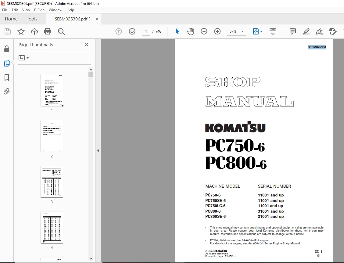
Komatsu PC750-6 PC800-6 Hydraulic Excavator Shop Manual SEBM025306 PDF
$32.95
Komatsu PC750-6 PC800-6 Hydraulic Excavator Shop Manual SEBM025306 – PDF DOWNLOAD
- MACHINE MODEL SERIAL NUMBER
PC750-6 11001 and up
PC750SE-6 11001 and up
PC750LC-6 11001 and up
PC800-6 31001 and up
PC800SE-6 31001 and up
Description
Komatsu PC750-6 PC800-6 Hydraulic Excavator Shop Manual SEBM025306 – PDF DOWNLOAD
FILE DETAILS:
Komatsu PC750-6 PC800-6 Hydraulic Excavator Shop Manual SEBM025306 – PDF DOWNLOAD
Language : English
Pages : 776
Downloadable : Yes
File Type : PDF
IMAGES PREVIEW OF THE MANUAL:
TABLE OF CONTENTS:
Komatsu PC750-6 PC800-6 Hydraulic Excavator Shop Manual SEBM025306 – PDF DOWNLOAD
- MACHINE MODEL SERIAL NUMBER
PC750-6 11001 and up
PC750SE-6 11001 and up
PC750LC-6 11001 and up
PC800-6 31001 and up
PC800SE-6 31001 and up
COVER 1
CONTENTS 2
01 GENERAL 29
SPECIFICATION DRAWINGS 30
SPECIFICATIONS 34
WEIGHT TABLE 42
FUEL, COOLANT AND LUBRICANTS 46
10 STRUCTURE, FUNCTION AND MAINTENANCE STANDARD 47
PTO 48
PTO LUBRICATION SYSTEM 49
POWER TRAIN 50
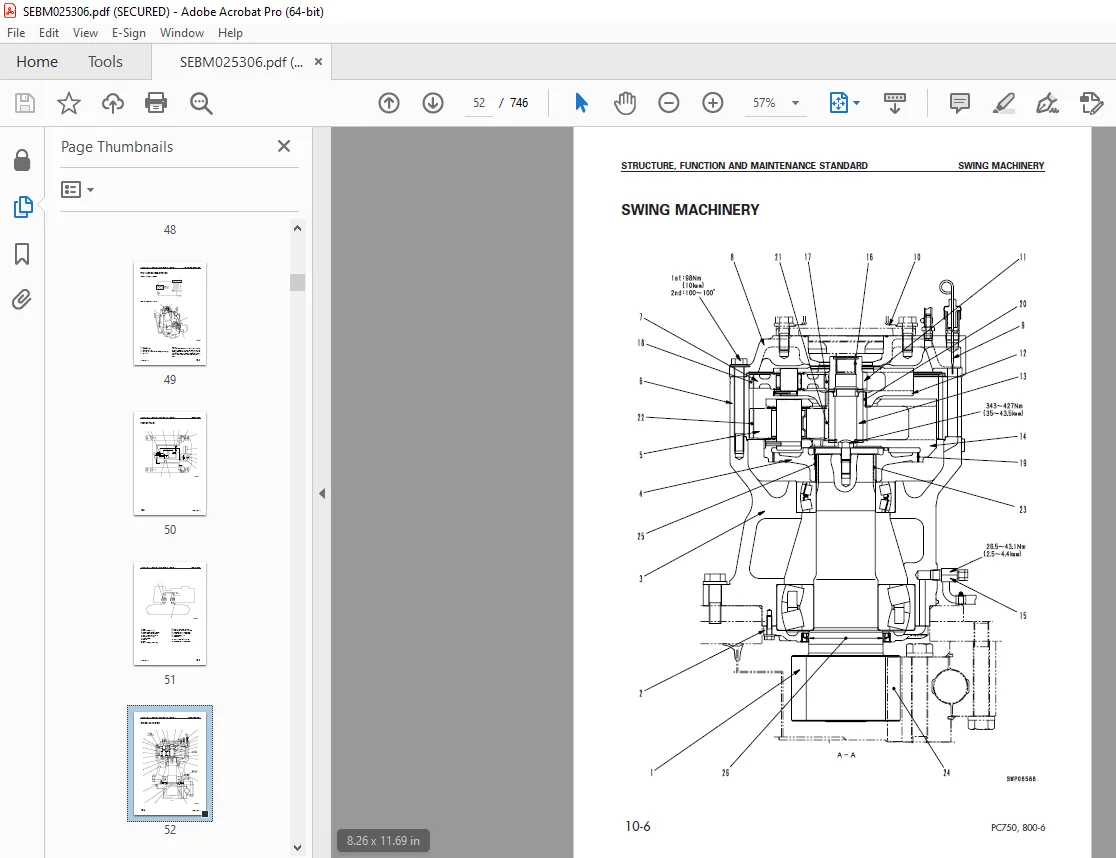
SWING MACHINERY 52
SWING CIRCLE 54
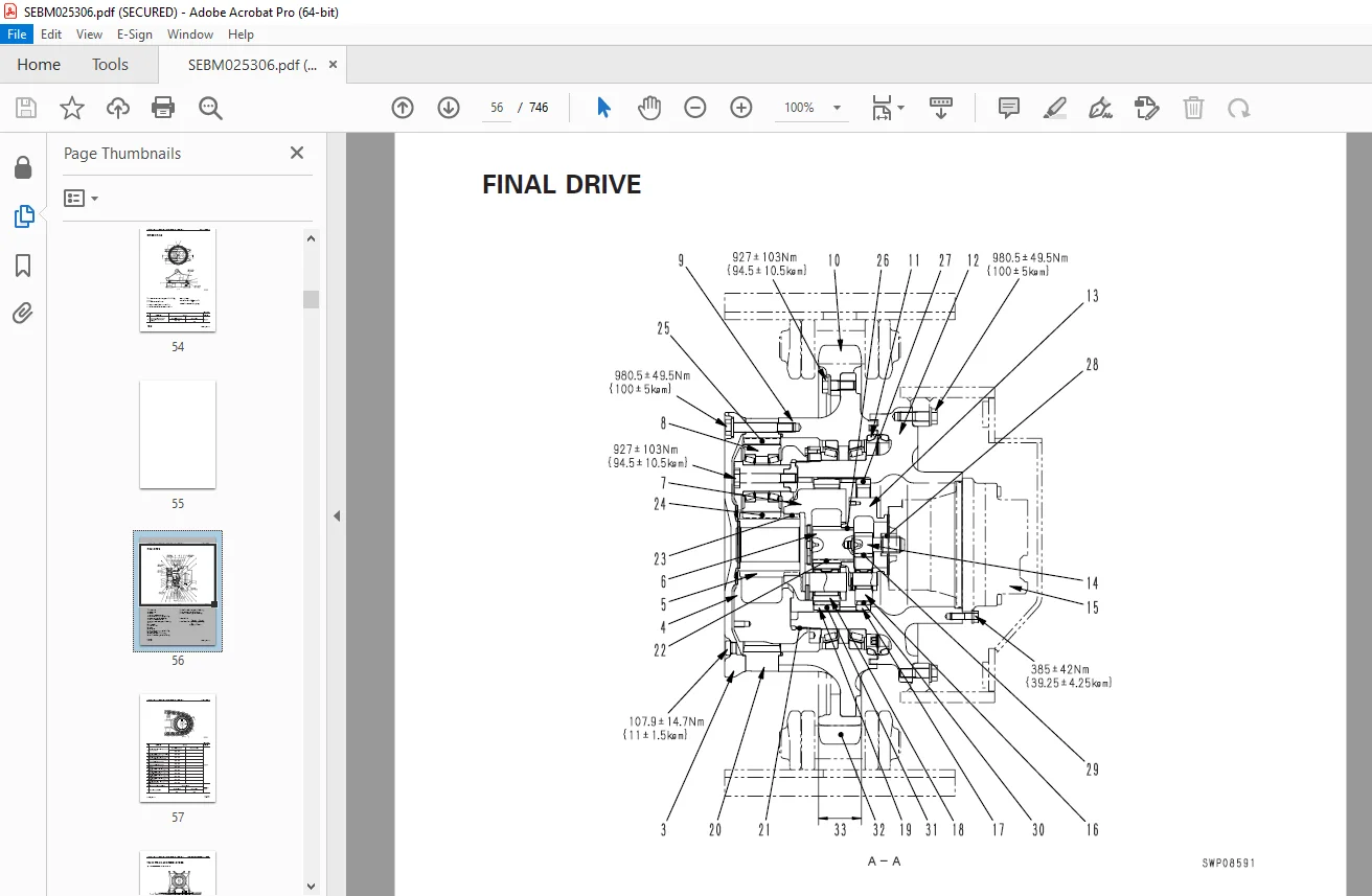
FINAL DRIVE 56
TRACK FRAME AND RECOIL SPRING 58
IDLER 60
CARRIER ROLLER 62
TRACK ROLLER 63
TRACK SHOE 64
MOTOR GREASE PUMP 69
HYDRAULIC TANK 70
HYDRAULIC PUMP 72
LINE OIL FILTER 102
PILOT OIL FILTER 102
DRAIN OIL FILTER 103
L H 5-SPOOL CONTROL VALVE 104
R H 4-SPOOL CONTROL VALVE 110
STRAIGHT-TRAVEL VALVE 116
SWING MOTOR 119
CENTER SWIVEL JOINT 124
TRAVEL MOTOR 125
PPC CONTROL RELIEF VALVE 135
SAFETY LOCK VALVE 136
PPC ACCUMULATOR 137
VALVE CONTROL 138
WORK EQUIPMENT, SWING PPC VALVE 139
TRAVEL PPC VALVE 144
SOLENOID VALVE 148
HYDRAULIC CYLINDER 154
WORK EQUIPMENT 162
DIMENSIONS OF WORK EQUIPMENT 170
AIR CONDITIONER 174
ENGINE CONTROL 175
MACHINE CONTROL SYSTEM 180
MONITOR SYSTEM 208
SENSORS 215
20 TESTING AND ADJUSTING 219
STANDARD VALUE TABLE FOR ENGINE 220
STANDARD VALUE TABLE FOR CHASSIS 221
STANDARD VALUE TABLE FOR ELECTRICAL PARTS 230
TOOLS FOR TESTING, ADJUSTING, AND TROUBLESHOOTING 243
MEASURING AIR SUPPLY PRESSURE (BOOST PRESSURE) 246
MEASURING EXHAUST TEMPERATURE 247
MEASURING EXHAUST COLOR 248
ADJUSTING VALVE CLEARANCE 249
MEASURING BLOW-BY PRESSURE 250
MEASURING COMPRESSION PRESSURE 250
MEASURING ENGINE OIL PRESSURE 251
HANDLING EQUIPMENT IN FUEL CIRCUIT 252
RELEASING REMAINING PRESSURE IN FUEL SYSTEM 252
MEASURING FUEL PRESSURE 253
REDUCED CYLINDER MODE OPERATION FOR ENGINE 254
BLEEDING AIR FROM FUEL CIRCUIT 256
CHECKING FOR LEAKAGE IN FUEL CIRCUIT 258
TESTING AND ADJUSTING ALTERNATOR BELT TENSION 259
TESTING AND ADJUSTING FAN BELT TENSION 260
TESTING AND ADJUSTING AIR CONDITIONER COMPRESSOR DRIVE BELT TENSION 261
HANDLING ENGINE CONTROLLER HIGH VOLTAGE CIRCUIT 262
ADJUSTING ENGINE SPEED SENSOR 263
TESTING AND ADJUSTING HYDRAULIC PRESSURE IN WORK EQUIPMENT, SWING, TRAVEL CIRCUIT 264
TESTING AND ADJUSTING CONTROL PUMP CIRCUIT OIL PRESSURE 267
TESTING AND ADJUSTING PISTON PUMP CONTROL PRESSURE 269
MEASURING SERVO PISTON STROKE 275
MEASURING PPC VALVE OUTPUT PRESSURE 276
TESTING SOLENOID VALVE OUTPUT PRESSURE 277
ADJUSTING WORK EQUIPMENT, SWING PPC VALVE 278
TESTING TRAVEL DEVIATION 279
TESTING LOCATIONS CAUSING HYDRAULIC DRIFT OF WORK EQUIPMENT 282
MEASURING OIL LEAKAGE 283
TESTING CLEARANCE OF SWING CIRCLE BEARING 288
TESTING AND ADJUSTING TRACK SHOE TENSION 289
BLEEDING AIR 290
RELEASING REMAINING PRESSURE IN HYDRAULIC CIRCUIT 292
PROCEDURE FOR CHECKING DIODE 293
TROUBLESHOOTING 295
POINTS TO REMEMBER WHEN TROUBLESHOOTING 296
SEQUENCE OF EVENTS IN TROUBLESHOOTING 297
POINTS TO REMEMBER WHEN CARRYING OUT MAINTENANCE 298
CHECKS BEFORE TROUBLESHOOTING 306
CONNECTOR TYPES AND MOUNTING LOCATIONS 307
CONNECTION TABLE FOR CONNECTOR PIN NUMBERS 314
EXPLANATION OF CONTROL MECHANISM FOR ELECTRICAL SYSTEM 337
DISPLAY METHOD AND SPECIAL FUNCTIONS OF MONITOR PANEL 338
METHOD OF USING JUDGEMENT TABLE 353
METHOD OF USING TROUBLESHOOTING CHARTS 355
DETAILS OF TROUBLESHOOTING AND TROUBLESHOOTING PROCEDURE 356
TROUBLESHOOTING OF COMMUNICATION ABNORMALITY SYSTEM (N MODE) 361
ACTION TAKEN BY CONTROLLER WHEN ABNORMALITY OCCURS AND PROBLEMS ON MACHINE 362
ELECTRICAL CIRCUIT DIAGRAM FOR N MODE SYSTEM 364
N-1 [E117, E118 occur at same time] Monitor panel communication abnormality 365
N-2 [E117, E218 occur at same time] Engine controller communication abnormality 367
N-3 [E118, E955 occur at same time] Pump controller communication abnormality 369
TROUBLESHOOTING OF ENGINE CONTROLLER SYSTEM (E MODE) 371
ACTION TAKEN BY CONTROLLER AND CONDITION OF MACHINE WHEN ERROR CODE IS DISPLAYED 372
JUDGEMENT TABLE FOR ENGINE CONTROLLER AND ENGINE RELATED PARTS 380
ELECTRICAL CIRCUIT DIAGRAM FOR E MODE SYSTEM 382
E-1 [E91b] (Abnormality in engine speed Ne sensor system) is displayed 384
E-2 [E91C] (Abnormality in engine G rotation sensor system) is displayed 385
E-3 [E920] (Abnormality in model selection system) is displayed 386
E-4 [E922] (Engine overrun) is displayed 387
E-5 [E924] (Drop in engine oil pressure) is displayed 388
E-6 [E931] (Abnormality in fuel control dial sensor system) is displayed 389
E-7 [E934] (Abnormality in engine water high-temperature sensor system) is displayed 390
E-8 [E936] (Abnormality in engine oil pressure switch system) is displayed 391
E-9 [E93C] (Abnormality in boost pressure sensor system) is displayed 393
E-10 [E93d] (Abnormality in fuel temperature sensor system) is displayed 394
E-11 [E954] (Short circuit in starting switch C system) is displayed 395
E-12 [E955] (Abnormality in network system) is displayed 395
E-13 [E956] (Power source system abnormality 1) is displayed 396
E-14 [E957] (Power source system abnormality 2) is displayed 398
E-15 [E95A] (Abnormality in fuel injection amount adjustment switch signal) is displayed 398
E-16 [E96A] (Abnormality in engine water low-temperature sensor system) is displayed 399
E-17 [E970] (Excess current in fuel supply pump PCV1 system) is displayed 400
E-18 [E971] (Excess current in fuel supply pump PCV2 system) is displayed 401
E-19 [E974] (Disconnection in fuel supply pump PCV1 system) is displayed 402
E-20 [E975] (Disconnection in fuel supply pump PCV2 system) is displayed 403
E-21 [E977] (Abnormality in common rail fuel pressure sensor system) is displayed 404
E-22 [E979] (Common rail fuel high pressure abnormality 1) is displayed
[E97A] (Common rail fuel high pressure abnormality 2) is displayed 405
E-23 [E97b] (Fuel supply pump non-force feed 1) is displayed
[E97C] (Fuel supply pump non-force feed 2) is displayed 406
E-24 [E97d] (Abnormality in common rail fuel pressure) is displayed 408
E-25 [E980] (Defective engine controller) is displayed 408
E-26 [E981] (Disconnection in No 1 fuel injector system) is displayed 409
E-27 [E982] (Disconnection in No 2 fuel injector system) is displayed 410
E-28 [E983] (Disconnection in No 3 fuel injector system) is displayed 411
E-29 [E984] (Disconnection in No 4 fuel injector system) is displayed 412
E-30 [E985] (Disconnection in No 5 fuel injector system) is displayed 413
E-31 [E986] (Disconnection in No 6 fuel injector system) is displayed 414
E-32 [E98A] (Short circuit in No 1, No 2, No 3 fuel injector system) is displayed 415
E-33 [E98b] (Short circuit in No 3, No 4, No 5 fuel injector system) is displayed 419
TROUBLESHOOTING OF PUMP CONTROLLER SYSTEM (C MODE) 423
POINTS TO REMEMBER WHEN TROUBLESHOOTING CONTROLLER SYSTEM 424
ACTION TAKEN BY CONTROLLER WHEN ABNORMALITY OCCURS AND PROBLEMS ON MACHINE 426
JUDGEMENT TABLE FOR PUMP CONTROLLER AND HYDRAULIC RELATED PARTS 434
ELECTRICAL CIRCUIT DIAGRAM FOR C MODE SYSTEM 436
C-1 Abnormality in controller power source system (controller LED is OFF) 438
C-2 [E232] Short circuit in pump TVC solenoid system is displayed 439
C-3 [E233] Disconnection in pump TVC solenoid system is displayed 441
C-4 [E203] Short circuit in swing holding brake solenoid system is displayed 443
C-5 [E213] Disconnection in swing holding brake solenoid system is displayed 445
C-6 [E201] Short circuit in CO cancel solenoid system is displayed 447
C-7 [E211] Disconnection in CO cancel solenoid system is displayed 448
C-8 [E202] Short circuit in straight-travel solenoid system is displayed 449
C-9 [E212] Disconnection in straight-travel solenoid system is displayed 450
C-10 [E204] Short circuit in 2-stage relief solenoid system is displayed 451
C-11 [E214] Disconnection in 2-stage relief solenoid system is displayed 452
C-12 [E205] Short circuit in swing priority selector solenoid system is displayed 453
C-13 [E211] Disconnection in swing priority selector solenoid system is displayed 454
C-14 [E206] Short circuit in travel speed solenoid system is displayed 455
C-15 [E216] Disconnection in travel speed solenoid system is displayed 456
C-16 [E217] Model selection input error is displayed 457
C-17 [E227] Abnormality in engine speed sensor system is displayed 459
C-18 Abnormality in machine push-up solenoid system (no service code displayed 460
C-19 Abnormality in shockless boom solenoid system (no service code displayed) 462
C-20 [E207] Short circuit in flash light relay drive system is displayed 465
C-21 Flash light relay does not work 466
C-22 [E231] Abnormality (short circuit) in power source holding relay output system for step light is displayed 467
C-23 Step light switch does not work 468
C-24 [E302] Short circuit in step light relay drive system is displayed 469
C-25 [303] Disconnection in step light relay drive system is displayed 470
C-26 Step light does not light up 471
C-27 [E228] Abnormality in auto-deceleration output system is displayed 472
TROUBLESHOOTING OF ENGINE THROTTLE & PUMP CONTROLLER (INPUT SIGNAL SYSTEM) (F MODE) 473
ELECTRICAL CIRCUIT DIAGRAM FOR F MODE SYSTEM 474
F-1 [Bit pattern 20-(1)] Swing oil pressure switch does not light up 476
F-2 [Bit pattern 20-(2)] R H travel oil pressure switch does not light up 477
F-3 [Bit pattern 20-(3)] Boom LOWER oil pressure switch does not light up 478
F-4 [Bit pattern 20-(4)] Boom RAISE oil pressure switch does not light up 479
F-5 [Bit pattern 20-(5)] Arm IN oil pressure switch does not light up 480
F-6 [Bit pattern 20-(6)] Arm OUT oil pressure switch does not light up 481
F-7 [Bit pattern 21-(1)] Bucket CURL oil pressure switch does not light up 482
F-8 [Bit pattern 21-(2)] Bucket DUMP oil pressure switch does not light up 483
F-9 [Bit pattern 20-(5)] L H travel oil pressure switch does not light up 484
F-10 [Bit pattern 21-(4)] Service oil pressure switch does not light up 485
F-11 [Bit pattern 21-(3)] Swing lock switch does not light up 486
F-12 [Bit pattern 24-(1)] When step light switch is ON, it does not go out 487
F-13 [Bit pattern 24-(2)] When horn switch is ON, it does not go out 488
TROUBLESHOOTING OF HYDRAULIC, MECHANICAL SYSTEM (H MODE) 489
TABLE OF FAILURE MODES AND CAUSES 490
BEFORE CARRYING OUT TROUBLESHOOTING OF HYDRAULIC SYSTEM (H MODE) 492
H-1 Speeds of all work equipment, swing, travel are slow or lack power 495
H-2 There is excessive drop in engine speed, or engine stalls 496
H-3 No work equipment, travel, swing move 498
H-4 Abnormal noise generated (around pump) 499
H-5 Auto-deceleration does not work 499
H-6 Work equipment speed is slow (boom, arm, bucket) 500
H-7 Work equipment (boom, arm, bucket) does not move (but travel and swing are normal) 502
H-8 Excessive hydraulic drift 502
H-9 Excessive time lag 503
H-10 Excessive shock when boom is stopped 503
H-11 Defective actuation of machine push-up function 503
H-12 Travel deviation is excessive during compound operations 504
H-13 Machine deviates naturally to one side during travel operations 505
H-14 Deviation is excessive when starting 507
H-15 Travel speed is slow 508
H-16 Travel speed does not switch 509
H-17 Travel does not move (one side only) 509
H-18 Does not swing 510
H-19 Swing speed is slow or swing acceleration is poor 512
H-20 Swing speed is slow or swing acceleration is poor during compound operations with arm, bucket 513
H-21 Swing speed is slow or swing acceleration is poor during compound operations with boom RAISE when swing priority is ON 514
H-22 Excessive overrun when stopping swing 515
H-23 Excessive shock when stopping swing 516
H-24 Excessive abnormal noise when stopping swing 517
H-25 Excessive hydraulic drift of swing 518
TROUBLESHOOTING OF MACHINE MONITOR SYSTEM (M MODE) 519
ACTION TAKEN BY MONITOR PANEL WHEN ABNORMALITY OCCURS AND PROBLEMS ON MACHINE 520
ELECTRICAL CIRCUIT DIAGRAM FOR M MODE SYSTEM 522
M-1 [E101] (Abnormality in error data) or [E102] (Abnormality in clock data) is displayed 524
M-2 [E103] (Short circuit in buzzer output system) is displayed 525
M-3 [E104] (Air cleaner clogging detection) is displayed 526
M-4 [E108] (Engine water temperature 105°C) is displayed 526
M-5 When starting switch is turned ON, none of lamps on monitor panel light up for 3 seconds 527
M-6 When starting switch is turned ON, monitor panel lamps all stay lighted up and do not go out 529
M-7 When starting switch is turned ON, items lighted up on monitor panel are different from actual machine 529
M-8 When starting switch is turned ON (engine stopped), basic check items flash 530
M-9 Preheating is not being used but preheating display motor lamp lights up 533
M-10 When engine is started, basic check items flash 534
M-11 When starting switch is turned ON (engine stopped), CAUTION items and EMERGENCY STOP items flash 535
M-12 When engine is started, CAUTION items and EMERGENCY STOP items flash 536
M-13 Operation of alarm buzzer is not normal 540
M-14 Night lighting on monitor panel does not light up 542
M-15 Engine water temperature display is not normal 543
M-16 Fuel level gauge display is not normal 544
M-17 Swing lock switch is turned ON but swing lock monitor lamp does not light up 546
M-18 When swing brake release switch is set to RELEASE (EMERGENCY), swing lock monitor lamp does not flash 547
M-19 Service meter does not give normal display 548
M-20 Defective fuel level sensor system 549
M-21 Defective engine oil level sensor system 550
M-22 Defective coolant level sensor system 551
M-23 Defective hydraulic oil level sensor system 552
M-24 Wiper is not actuated when wiper switch is operated or wiper is actuated when wiper switch is not operated 553
M-25 Window washer is not actuated when wiper switch is operated or window washer is actuated when switch is not operated 558
M-26 Electric grease gun does not work (machines equipped with electric grease gun) 561
30 DISASSEMBLY AND ASSEMBLY 563
METHOD OF USING MANUAL 565
PRECAUTIONS WHEN CARRYING OUT OPERATION 568
SPECIAL TOOL LIST 570
SKETCHES OF SPECIAL TOOLS 577
FUEL SUPPLY PUMP ASSEMBLY 581
REMOVAL 581
INSTALLATION 583
FUEL INJECTOR ASSEMBLY 584
REMOVAL 584
INSTALLATION 586
NOZZLE TIP 588
REMOVAL 588
INSTALLATION 589
ENGINE FRONT SEAL 591
REMOVAL 591
INSTALLATION 591
ENGINE REAR SEAL 593
REMOVAL 593
INSTALLATION 594
CYLINDER HEAD ASSEMBLY 598
REMOVAL 598
INSTALLATION 601
AFTERCOOLER CORE 605
REMOVAL 605
INSTALLATION 605
FAN GUARD, RADIATOR AND HYDRAULIC OIL COOLER ASSEMBLY 606
REMOVAL 606
INSTALLATION 608
FUEL COOLER AND AIR CONDITIONER CONDENSER ASSEMBLY 609
REMOVAL 609
INSTALLATION 609
FUEL TANK ASSEMBLY 610
REMOVAL 610
INSTALLATION 611
ENGINE, PTO AND HYDRAULIC PUMP ASSEMBLY 612
REMOVAL 612
INSTALLATION 616
PTO ASSEMBLY 617
REMOVAL 617
INSTALLATION 618
DISASSEMBLY 619
ASSEMBLY 620
FINAL DRIVE ASSEMBLY 623
DISASSEMBLY 623
ASSEMBLY 628
REVOLVING FRAME ASSEMBLY 636
REMOVAL 636
INSTALLATION 637
SWING MACHINERY ASSEMBLY 638
REMOVAL 638
INSTALLATION 638
DISASSEMBLY 639
ASSEMBLY 643
SWING CIRCLE ASSEMBLY 648
REMOVAL 648
INSTALLATION 648
TRACK SHOE ASSEMBLY 649
REMOVAL 649
INSTALLATION 650
ONE LINK IN FIELD 651
DISASSEMBLY 651
ASSEMBLY 653
IDLER ASSEMBLY 655
REMOVAL 655
INSTALLATION 655
DISASSEMBLY 656
ASSEMBLY 658
IDLER ADJUSTMENT CYLINDER ASSEMBLY 660
DISASSEMBLY 660
ASSEMBLY 660
RECOIL SPRING ASSEMBLY 661
REMOVAL 661
INSTALLATION 661
DISASSEMBLY 663
ASSEMBLY 664
CARRIER ROLLER ASSEMBLY 665
REMOVAL 665
INSTALLATION 665
DISASSEMBLY 666
ASSEMBLY 667
TRACK ROLLER ASSEMBLY 668
REMOVAL 668
INSTALLATION 668
DISASSEMBLY 669
ASSEMBLY 670
HYDRAULIC TANK ASSEMBLY 672
REMOVAL 672
INSTALLATION 674
MAIN PUMP (NO 1 PUMP) ASSEMBLY 675
REMOVAL 675
INSTALLATION 676
MAIN PUMP (NO 2 PUMP) 677
REMOVAL 677
INSTALLATION 678
MAIN PUMP INPUT SHAFT OIL SEAL 679
REMOVAL 679
INSTALLATION 679
CONTROL • PTO LUBRICATION PUMP ASSEMBLY 680
REMOVAL 680
INSTALLATION 680
MAIN RELIEF VALVE ASSEMBLY 681
DISASSEMBLY 681
ASSEMBLY 681
CONTROL VALVE ASSEMBLY 682
REMOVAL 682
INSTALLATION 684
DISASSEMBLY 686
ASSEMBLY 688
SOLENOID VALVE ASSEMBLY 690
REMOVAL 690
INSTALLATION 691
BOOM DAMPING VALVE ASSEMBLY 692
REMOVAL 692
INSTALLATION 692
SWING MOTOR ASSEMBLY 693
REMOVAL 693
INSTALLATION 693
CENTER SWIVEL JOINT 694
REMOVAL 694
INSTALLATION 694
DISASSEMBLY 695
ASSEMBLY 695
TRAVEL MOTOR ASSEMBLY 696
REMOVAL 696
INSTALLATION 696
WORK EQUIPMENT PPC VALVE ASSEMBLY 697
DISASSEMBLY 697
ASSEMBLY 698
TRAVEL PPC VALVE ASSEMBLY 699
DISASSEMBLY 699
ASSEMBLY 700
BUCKET CYLINDER ASSEMBLY 701
REMOVAL 701
INSTALLATION 703
ARM CYLINDER ASSEMBLY 705
REMOVAL 705
INSTALLATION 707
BOOM CYLINDER ASSEMBLY 709
REMOVAL 709
INSTALLATION 711
BOTTOM DUMP CYLINDER ASSEMBLY 713
REMOVAL 713
INSTALLATION 714
HYDRAULIC CYLINDER ASSEMBLY 715
DISASSEMBLY 715
ASSEMBLY 717
BUCKET ASSEMBLY 720
REMOVAL 720
INSTALLATION 722
ARM ASSEMBLY 724
REMOVAL 724
INSTALLATION 726
BOOM ASSEMBLY 728
REMOVAL 728
INSTALLATION 730
WORK EQUIPMENT 732
REMOVAL 732
INSTALLATION 734
OPERATOR’S CAB ASSEMBLY 736
REMOVAL 736
INSTALLATION 737
COUNTERWEIGHT ASSEMBLY 738
REMOVAL 738
INSTALLATION 738
90 OTHERS 739
HYDRAULIC CIRCUIT DRAWING (BACKHOE SPECIFICATION) 741
HYDRAULIC CIRCUIT DRAWING (LOADING SHOVEL SPECIFICATION) 742
ELECTRIC CIRCUIT DIAGRAM (1/4) 743
ELECTRIC CIRCUIT DIAGRAM (2/4) 744
ELECTRIC CIRCUIT DIAGRAM (3/4) 745
ELECTRIC CIRCUIT DIAGRAM (4/4) 746
DESCRIPTION:
Komatsu PC750-6 PC800-6 Hydraulic Excavator Shop Manual SEBM025306 – PDF DOWNLOAD
- MACHINE MODEL SERIAL NUMBER
PC750-6 11001 and up
PC750SE-6 11001 and up
PC750LC-6 11001 and up
PC800-6 31001 and up
PC800SE-6 31001 and up
GENERAL PRECAUTIONS:
Mistakes in operation are extremely dangerous. Read the Operation and Maintenance Manual carefully BEFORE operating the machine.
1. Before carrying out any greasing or repairs, read all the precautions given on the decals which are fixed to the machine.
2. When carrying out any operation, always wear safety shoes and helmet. Do not wear loose work clothes, or clothes with buttons missing.
• Always wear safety glasses when hitting parts with a hammer.
Always wear safety glasses when grinding parts with a grinder, etc.
3. If welding repairs are needed, always have a trained, experienced welder carry out the work. When carrying out welding work, always wear welding gloves, apron, glasses, cap and other clothes suited for welding work.
4. When carrying out any operation with two or more workers, always agree on the operating procedure before starting. Always inform your fellow workers before starting any step of the operation. Before starting work, hang UNDER REPAIR signs on the controls in the operator’s compartment.
5. Keep all tools in good condition and learn the correct way to use them.
6. Decide a place in the repair workshop to keep tools and removed parts. Always keep the tools and parts in their correct places. Always keep the work area clean and make sure that there is no dirt or oil on the floor. Smoke only in the areas provided for smoking. Never smoke while working.
PREPARATIONS FOR WORK:
7. Before adding oil or making any repairs, park the machine on hard, level ground, and block the wheels or tracks to prevent the machine from moving.
8. Before starting work, lower blade, ripper, bucket or any other work equipment to the ground. If this is not possible, insert the safety pin or use blocks to prevent the work equipment from falling. In addition, be sure to lock all the control levers and hang warning signs on them.
9. When disassembling or assembling, sup- port the machine with blocks, jacks or stands before starting work.
10. Remove all mud and oil from the steps or other places used to get on and off the machine. Always use the handrails, ladders or steps when getting on or off the machine. Never jump on or off the machine. If it is impossible to use the handrails, ladders or steps, use a stand to provide safe footing.
PRECAUTIONS DURING WORK:
11. When removing the oil filler cap, drain plug or hydraulic pressure measuring plugs, loosen them slowly to prevent the oil from spurting out.
Before disconnecting or removing components of the oil, water or air circuits, first remove the pressure completely from the circuit.
12. The water and oil in the circuits are hot when the engine is stopped, so be careful not to get burned.
Wait for the oil and water to cool before carrying out any work on the oil or water circuits.
13. Before starting work, remove the leads from the battery. Always remove the lead from the negative (-) terminal first.
14. When raising heavy components, use a hoist or crane.
Check that the wire rope, chains and hooks are free from damage.
Always use lifting equipment which has ample capacity.
Install the lifting equipment at the correct places. Use a hoist or crane and operate slowly to prevent the component from hit- ting any other part. Do not work with any part still raised by the hoist or crane.
15. When removing covers which are under internal pressure or under pressure from a spring, always leave two bolts in position on opposite sides. Slowly release the pressure, then slowly loosen the bolts to remove.
16. When removing components, be careful not to break or damage the wiring. Damaged wiring may cause electrical fires.
17. When removing piping, stop the fuel or oil from spilling out. If any fuel or oil drips on to the floor, wipe it up immediately. Fuel or oil on the floor can cause you to slip, or can even start fires.
G.B 18/12/24



