
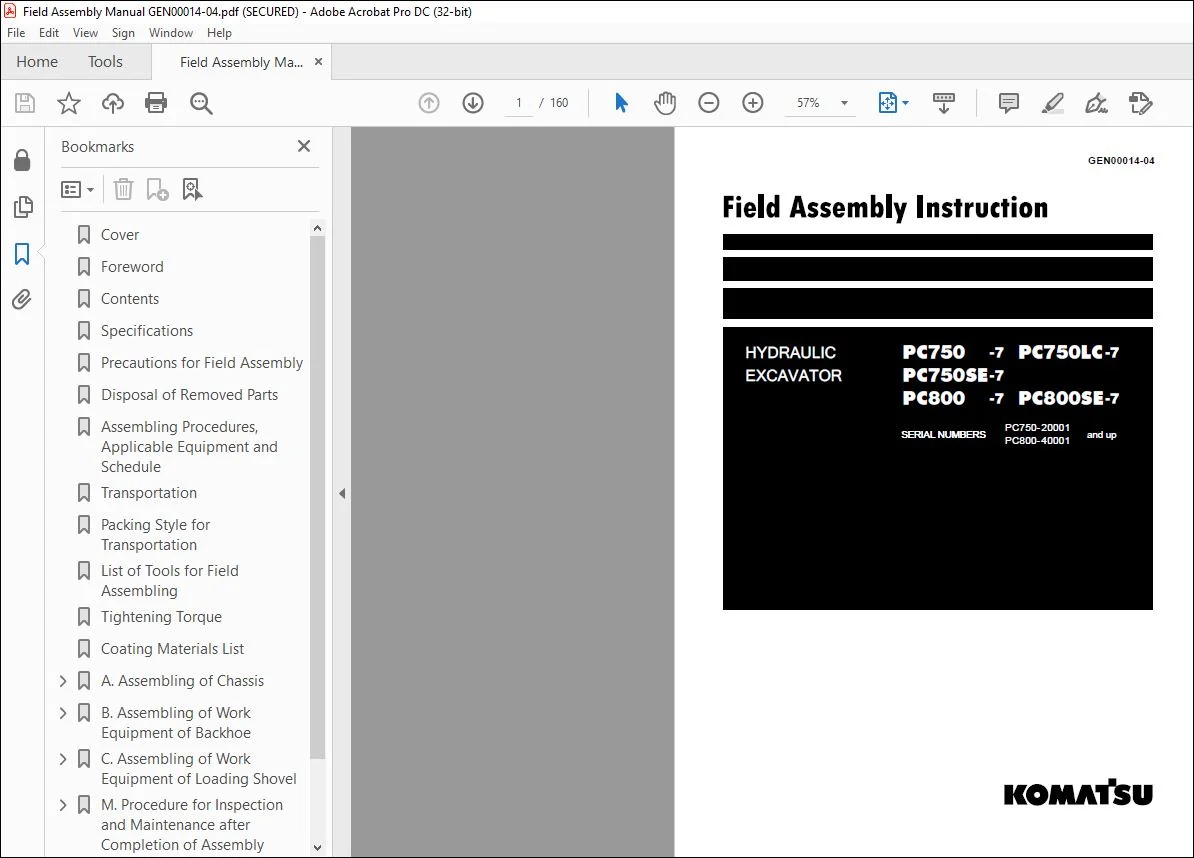
Komatsu PC750-7 PC750LC-7 PC750SE-7 PC800-7 PC800SE-7 Hydraulic Excavator Field Assembly Manual GEN00014-04 – PDF DOWNLOAD
Original price was: $89.95.$26.95Current price is: $26.95.
Komatsu PC750-7 PC750LC-7 PC750SE-7 PC800-7 PC800SE-7 Hydraulic Excavator Field Assembly Manual GEN00014-04 – PDF DOWNLOAD
SERIAL NUMBERS
PC750-20001 and up
PC800-40001 and up
Description
Komatsu PC750-7 PC750LC-7 PC750SE-7 PC800-7 PC800SE-7 Hydraulic Excavator Field Assembly Manual GEN00014-04 – PDF DOWNLOAD
IMAGES PREVIEW OF THE MANUAL:
DESCRIPTION:
Komatsu PC750-7 PC750LC-7 PC750SE-7 PC800-7 PC800SE-7 Hydraulic Excavator Field Assembly Manual GEN00014-04 – PDF DOWNLOAD
SERIAL NUMBERS
PC750-20001 and up
PC800-40001 and up
Foreword:
Since this machine is large in size, it is divided into some units to meet the transportation conditions and regulations applied to the transporta- tion route when shipped from our factory. This manual describes how to assemble the units into the complete machine in the field.
- We hope that this machine will display its quality and you will use it safely according to the operation manual. Many units are large in size and heavy in weight and may be handled in a dangerous place or posture and many workers may have to work together to sling them with cranes.
- Accordingly, before starting the assembly work, the work supervisor is required to hold a safety meeting to oblige the workers to put on pro- tective gear and appoint a work leader and a crane work signal man and allot roles to all the workers for safe work. In particular, the above meeting is more important when worker of dif- ferent languages and customs work together.
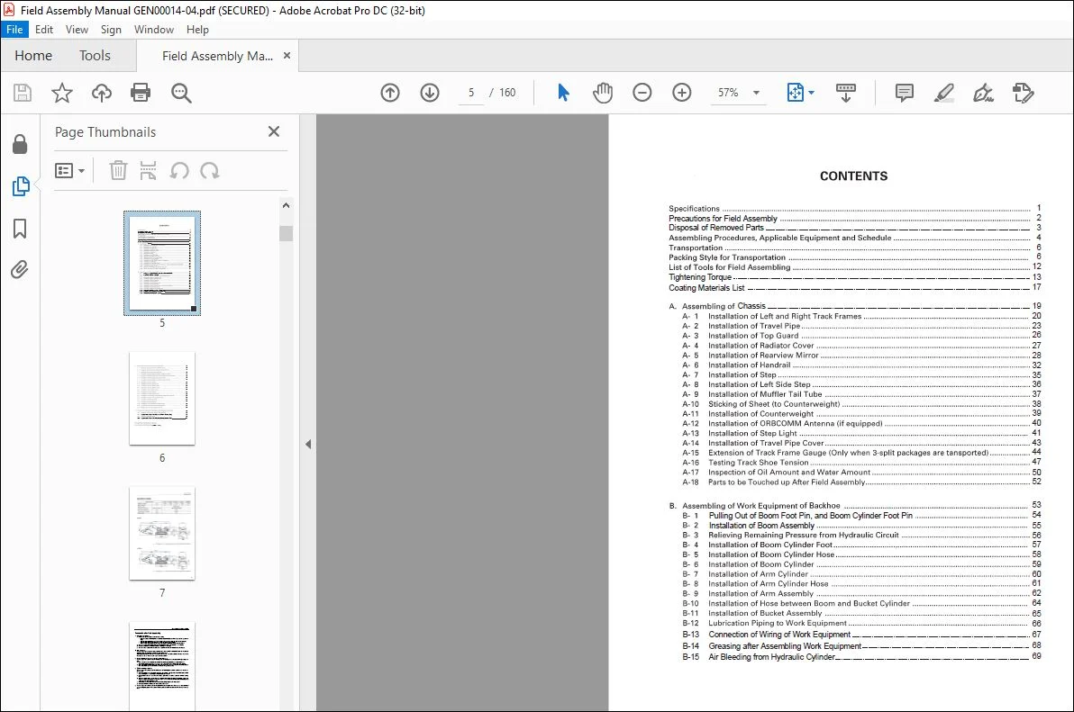
TABLE OF CONTENTS:
Komatsu PC750-7 PC750LC-7 PC750SE-7 PC800-7 PC800SE-7 Hydraulic Excavator Field Assembly Manual GEN00014-04 – PDF DOWNLOAD
Cover 1
Foreword 3
Contents 5
Specifications 7
Precautions for Field Assembly 8
Disposal of Removed Parts 9
Assembling Procedures, Applicable Equipment and Schedule 10
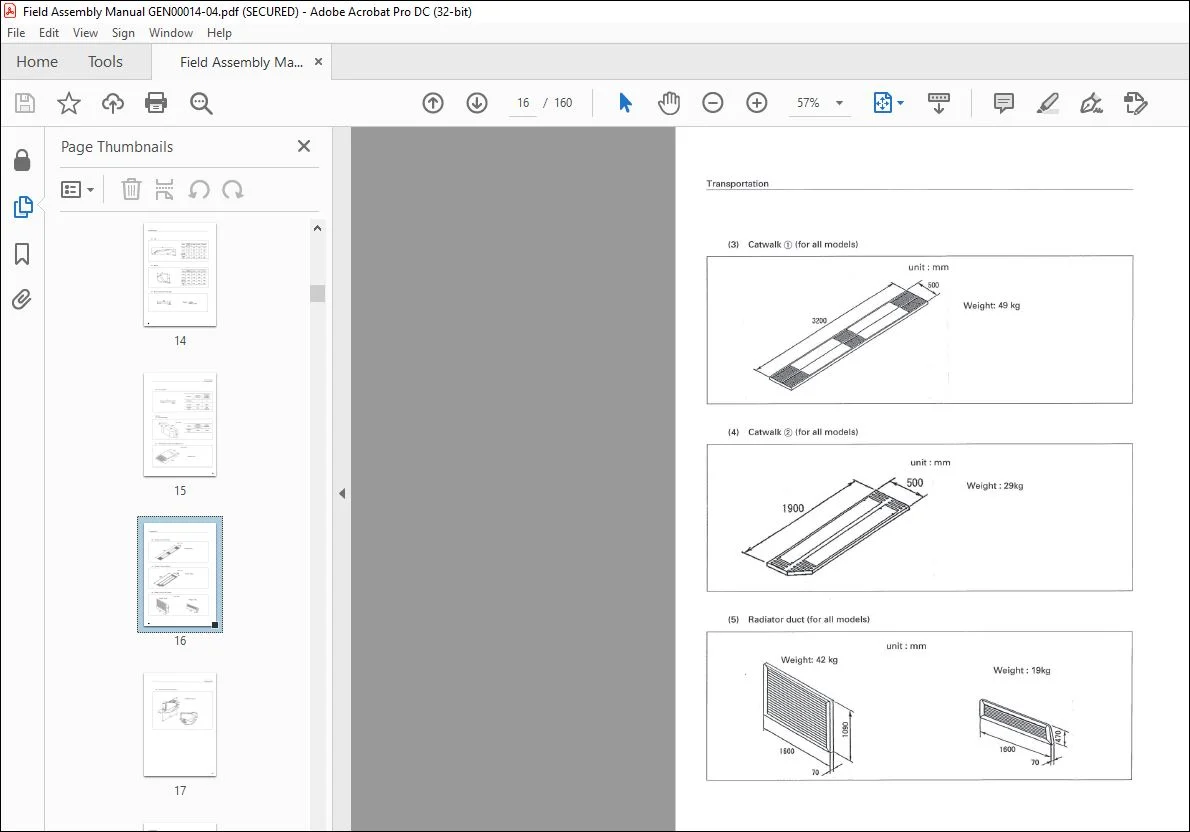
Transportation 12
Packing Style for Transportation 12
List of Tools for Field Assembling 18
Tightening Torque 19
Coating Materials List 23
A Assembling of Chassis 25
A-1 Installation of Left and Right Track Frames 26
A-2 Installation of Travel Pipe 29
A-3 Installation of Top Guard 32
A-4 Installation of Radiator Cover 33
A-5 Installation of Rearview Mirror 34
A-6 Installation of Handrail 38
A-7 Installation of Step 41
A-8 Installation of Left Side Step 42
A-9 Installation of Muffler Tail Tube 43
A-10 Sticking of Sheet (to Counterweight) 44
A-11 Installation of Counterweight 45
A-12 Installation of ORBCOMM Antenna (if equipped) 46
A-13 Installation of Step Light 47
A-14 Installation of Travel Pipe Cover 49
A-15 Extension of Track Frame Gauge (Only when 3-split packages are tansported) 50
A-16 Testing Track Shoe Tension 53
A-17 Inspection of Oil Amount ans Water Amount 56
A-18 Parts to be Touched up After Field Assembly 58
B Assembling of Work Equipment of Backhoe 59
B-1 Pulling Out of Boom Foot Pin, and Boom Cylinder Foot Pin 60
B-2 Installation of Boom Assembly 61
B-3 Relieving Remaining Pressure from Hydraulic Circuit 62
B-4 Installation of Boom Cylinder Foot 63
B-5 Installation of Boom Cylinder Hose 64
B-6 Installation of Boom Cylinder 65
B-7 Installation of Arm Cylinder 66
B-8 Installation of Arm Cylinder Hose 67
B-9 Installation of Arm Assembly 68
B-10 Installation of of Hose between Boom and Bucket Cylinder 70
B-11 Installation of Bucket Assembly 71
B-12 Lubrication Piping to Work Equipment 72
B-13 Connection of Wiring of Work Equipment 73
B-14 Greasing after Assembling Work Equipment 74
B-15 Air Bleeding from Hydraulic Cylinder 75
C Assembling of Work Equipment of Loading Shovel 77
C-1 Releasing residual pressure in hydraulic circuit 78
C-2 Pulling out boom foot pin and boom cylinder foot pin 79
C-3 Installation of boom and arm assembly 80
C-4 Installation of flushing piping between chassis and boom 81
C-5 Installation of flushing piping for boom cylinder and arm cylinder 82
C-6 Installation of flushing piping for bucket cylinder 83
C-7 Installation of flushing piping for bottom dump cylinder 84
C-8 Installation of boom cylinder 86
C-9 Installation of boom cylinder foot 87
C-10 Installation of boom cylinder hoses 88
C-11 Installation of boom cylinder rod pin 89
C-12 Installation of arm cylinder hoses 90
C-13 Installation of bucket cylinder 91
C-14 Installation of bucket cylinder hose 92
C-15 Installation of connecting hoses between chassis and boom top 93
C-16 Installation of bottom dump cylinder hose 94
C-17 Installation of bucket assembly 95
C-18 Installation of working lamps 97
C-19 Installation of work equipment drease piping 98
C-20 Greasing after assembling of work equipment 99
C-21 Bleeding air from work equipment circuit 100
M Procedure for Inspection and Maintenance after Completion of Assembly 101
M-1 Inspection of Oil level in Hydraulic Tank and Refill 102
M-2 Replacement of Return Filter (Standard Filter to Flushing Filter) 104
M-3 Flushing of Hydraulic Circuit 105
M-4 Replacement of Return Filter (Flushing Filter to Standard Filter) 107
Field Assembly Inspection Report (Backhoe) 109
Field Assembly Inspection Report (Loading Shovel) 135
Customer Support: [email protected]
https://vimeo.com/743012083
PLEASE NOTE:
- This is the same manual used by the dealers to diagnose and troubleshoot your vehicle
- You will be directed to the download page as soon as the purchase is completed. The whole payment and downloading process will take anywhere between 2-5 minutes
- Need any other service / repair / parts manual, please feel free to contact [email protected] . We still have 50,000 manuals unlisted
S.V



