Komatsu PC750SE-6K, PC750LC-6K Hydraulic Excavator Shop Manual K32001 and up – PDF DOWNLOAD
Original price was: $65.95.$28.95Current price is: $28.95.
Komatsu PC750SE-6K, PC750LC-6K Hydraulic Excavator Shop Manual
Book Code: UEBM001801
MACHINE MODEL SERIAL NUMBER
PC750SE-6 K32001 and up
PC750LC-6 K32001 and up
Description
Komatsu PC750SE-6K, PC750LC-6K Hydraulic Excavator Shop Manual
FILE DETAILS:
Komatsu PC750SE-6K, PC750LC-6K Hydraulic Excavator Shop Manual
Brands: Komatsu
Equipment Type: Hydraulic Excavator
Manuals Type: Shop Manual
Machine Model: PC750SE-6K, PC750LC-6K
Serial Number: K32001 and up
Book Code: UEBM001801
Language: English
Pages: 701
File Format: Portable Document Format (PDF)
KOMATSU PC750SE-6K, PC750LC-6K HYDRAULIC EXCAVATOR SHOP MANUAL K32001 AND UP – PDF DOWNLOAD:
IMAGES PREVIEW OF THE MANUAL:
DESCRIPTION:
Komatsu PC750SE-6K, PC750LC-6K Hydraulic Excavator Shop Manual
FOREWORD:
GENERAL:
- This shop manual has been prepared as an aid to improve the quality of repairs by giving the serviceman an accurate understanding of the product and by showing him the correct way to perform repairs and make judgements. Make sure you understand the contents of this manual and use it to full effect at every opportunity.
- This shop manual mainly contains the necessary technical information for operations performed in a service workshop. For ease of understanding, the manual is divided into the following chapters; these chapters are further divided into the each main group of components.
STRUCTURE AND FUNCTION:
This section explains the structure and function of each component. It serves not only to give an understanding of the structure, but also serves as reference material for troubleshooting. In addition, this section may contain hydraulic circuit diagrams, electric circuit diagrams, and maintenance standards.
TESTING AND ADJUSTING:
This section explains checks to be made before and after performing repairs, as well as adjustments to be made at completion of the checks and repairs. Troubleshooting charts correlating “Problems” with “Causes” are also included in this section.
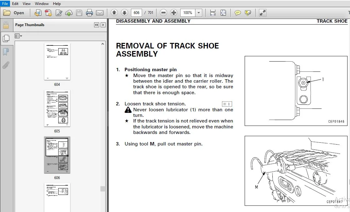
DISASSEMBLY AND ASSEMBLY:
This section explains the procedures for removing, installing, disassembling and assembling each component, as well as precautions for them.
MAINTENANCE STANDARD:
This section gives the judgment standards for inspection of disassembled parts. The contents of this section may be described in STRUCTURE AND FUNCTION.
OTHERS:
This section mainly gives hydraulic circuit diagrams and electric circuit diagrams. In addition, this section may give the specifications of attachments and options together.
TABLE OF CONTENTS:
Komatsu PC750SE-6K, PC750LC-6K Hydraulic Excavator Shop Manual
GENERAL .......................................................................................................................................................................................................................................................................... 29
	SPECIFICATION DRAWINGS ....................................................................................................................................................................................................................................................... 30
	FUEL, COOLANT AND LUBRICANTS ................................................................................................................................................................................................................................................. 38
PTO .............................................................................................................................................................................................................................................................................. 40
PTO LUBRICATION SYSTEM ........................................................................................................................................................................................................................................................... 41
POWER TRAIN SWING MACHINERY SWING CIRCLE ......................................................................................................................................................................................................................................... 46
FINAL DRIVE ...................................................................................................................................................................................................................................................................... 48
TRACK FRAME AND RECOIL SPRING .................................................................................................................................................................................................................................................... 50
IDLER CARRIER ROLLER ............................................................................................................................................................................................................................................................. 54
TRACK ROLLER ..................................................................................................................................................................................................................................................................... 55
TRACK SHOE ( 1/ 2) ............................................................................................................................................................................................................................................................... 56
( 2/ 2) .......................................................................................................................................................................................................................................................................... 58
MOTOR GREASE PUMP ................................................................................................................................................................................................................................................................ 61
HYDRAULIC TANK ................................................................................................................................................................................................................................................................... 62
HYDRAULIC PUMP ................................................................................................................................................................................................................................................................... 64
LINE OIL FILTER .................................................................................................................................................................................................................................................................. 94
PILOT OIL FILTER ................................................................................................................................................................................................................................................................. 94
DRAIN OIL FILTER ................................................................................................................................................................................................................................................................. 95
L. H. 5- SPOOL CONTROL VALVE ..................................................................................................................................................................................................................................................... 96
R. H. 4- SPOOL CONTROL VALVE .....................................................................................................................................................................................................................................................102
STRAIGHT- TRAVEL VALVE ...........................................................................................................................................................................................................................................................108
SWING MOTOR ......................................................................................................................................................................................................................................................................111
CENTER SWIVEL JOINT ..............................................................................................................................................................................................................................................................116
TRAVEL MOTOR .....................................................................................................................................................................................................................................................................117
PPC CONTROL RELIEF VALVE .........................................................................................................................................................................................................................................................127
SAFETY LOCK VALVE ................................................................................................................................................................................................................................................................128
PPC ACCUMULATOR ..................................................................................................................................................................................................................................................................129
VALVE CONTROL ....................................................................................................................................................................................................................................................................130
WORK EQUIPMENT, SWING PPC VALVE ..................................................................................................................................................................................................................................................131
TRAVEL PPC VALVE .................................................................................................................................................................................................................................................................136
SOLENOID VALVE ...................................................................................................................................................................................................................................................................140
HYDRAULIC CYLINDER ...............................................................................................................................................................................................................................................................146
WORK EQUIPMENT ...................................................................................................................................................................................................................................................................150
DIMENSIONS OF WORK EQUIPMENT .....................................................................................................................................................................................................................................................154
AIR CONDITIONER ..................................................................................................................................................................................................................................................................158
ENGINE CONTROL ...................................................................................................................................................................................................................................................................159
MACHINE CONTROL SYSTEM ...........................................................................................................................................................................................................................................................164
MONITOR SYSTEM ...................................................................................................................................................................................................................................................................192
SENSORS ..........................................................................................................................................................................................................................................................................199
TESTING AND ADJUSTING ............................................................................................................................................................................................................................................................203
	STANDARD VALUE TABLE FOR ENGINE ..............................................................................................................................................................................................................................................204
	STANDARD VALUE TABLE FOR CHASSIS .............................................................................................................................................................................................................................................205
STANDARD VALUE TABLE FOR ELECTRICAL PARTS ........................................................................................................................................................................................................................................214
TOOLS FOR TESTING, ADJUSTING, AND TROUBLESHOOTING ................................................................................................................................................................................................................................227
MEASURING AIR SUPPLY PRESSURE ( BOOST PRESSURE) ..................................................................................................................................................................................................................................230
MEASURING EXHAUST TEMPERATURE ....................................................................................................................................................................................................................................................231
MEASURING EXHAUST COLOR ..........................................................................................................................................................................................................................................................232
ADJUSTING VALVE CLEARANCE ........................................................................................................................................................................................................................................................233
MEASURING BLOW- BY PRESSURE ......................................................................................................................................................................................................................................................234
MEASURING COMPRESSION PRESSURE ...................................................................................................................................................................................................................................................234
MEASURING ENGINE OIL PRESSURE ....................................................................................................................................................................................................................................................235
HANDLING EQUIPMENT IN FUEL CIRCUIT ...............................................................................................................................................................................................................................................236
RELEASING REMAINING PRESSURE IN FUEL SYSTEM ......................................................................................................................................................................................................................................236
MEASURING FUEL PRESSURE ..........................................................................................................................................................................................................................................................237
REDUCED CYLINDER MODE OPERATION FOR ENGINE .......................................................................................................................................................................................................................................238
BLEEDING AIR FROM FUEL CIRCUIT ...................................................................................................................................................................................................................................................240
CHECKING FOR LEAKAGE IN FUEL CIRCUIT .............................................................................................................................................................................................................................................242
TESTING AND ADJUSTING ALTERNATOR BELT TENSION ....................................................................................................................................................................................................................................243
TESTING AND ADJUSTING FAN BELT TENSION ...........................................................................................................................................................................................................................................244
TESTING AND ADJUSTING AIR CONDITIONER COMPRESSOR DRIVE BELT TENSION ..............................................................................................................................................................................................................245
HANDLING ENGINE CONTROL- LER HIGH VOLTAGE CIRCUIT ................................................................................................................................................................................................................................246
ADJUSTING ENGINE SPEED SENSOR ....................................................................................................................................................................................................................................................247
TESTING AND ADJUSTING HYDRAULIC PRESSURE IN WORK EQUIPMENT, SWING, TRAVEL CIRCUIT ................................................................................................................................................................................................248
TESTING AND ADJUSTING CONTROL PUMP CIRCUIT OIL PRESSURE ..........................................................................................................................................................................................................................251
TESTING AND ADJUSTING PISTON PUMP CONTROL PRESSURE ...............................................................................................................................................................................................................................253
MEASURING SERVO PISTON STROKE ....................................................................................................................................................................................................................................................259
MEASURING PPC VALVE OUT- PUT PRESSURE ............................................................................................................................................................................................................................................260
TESTING SOLENOID VALVE OUTPUT PRESSURE ...........................................................................................................................................................................................................................................261
ADJUSTING WORK EQUIP- MENT, SWING PPC VALVE ......................................................................................................................................................................................................................................262
TESTING TRAVEL DEVIATION .........................................................................................................................................................................................................................................................263
TESTING LOCATIONS CAUSING HYDRAULIC DRIFT OF WORK EQUIPMENT ......................................................................................................................................................................................................................266
MEASURING OIL LEAKAGE ............................................................................................................................................................................................................................................................267
TESTING CLEARANCE OF SWING CIRCLE BEARING ........................................................................................................................................................................................................................................272
TESTING AND ADJUSTING TRACK SHOE TENSION .........................................................................................................................................................................................................................................273
BLEEDING AIR .....................................................................................................................................................................................................................................................................274
RELEASING REMAINING PRESSURE IN HYDRAULIC CIRCUIT ................................................................................................................................................................................................................................276
PROCEDURE FOR CHECKING DIODE .....................................................................................................................................................................................................................................................277
POINTS TO REMEMBER WHEN TROUBLESHOOTING ..........................................................................................................................................................................................................................................280
SEQUENCE OF EVENTS IN TROUBLESHOOTING POINTS TO REMEMBER WHEN CARRYING OUT MAINTENANCE CHECKS BEFORE TROUBLESHOOTING .............................................................................................................................................................290
CONNECTOR TYPES AND MOUNTING LOCATIONS ...........................................................................................................................................................................................................................................291
CONNECTION TABLE FOR CONNECTOR PIN NUMBERS .......................................................................................................................................................................................................................................298
EXPLANATION OF CONTROL MECHANISM FOR ELECTRICAL SYSTEM ...........................................................................................................................................................................................................................321
DISPLAY METHOD AND SPECIAL FUNCTIONS OF MONITOR PANEL ............................................................................................................................................................................................................................322
METHOD OF USING JUDGEMENT TABLE ..................................................................................................................................................................................................................................................337
METHOD OF USING TROUBLESHOOTING CHARTS ...........................................................................................................................................................................................................................................339
DETAILS OF TROUBLESHOOTING AND TROUBLESHOOTING PROCEDURE .........................................................................................................................................................................................................................340
ACTION TAKEN BY CONTROLLER WHEN ABNORMALITY OCCURS AND PROBLEMS ON MACHINE .......................................................................................................................................................................................................346
N- 1 [ E117, E118 occur at same time ] Monitor panel communication abnormality ...................................................................................................................................................................................................349
N- 2 [ E117, E218 occur at same time ] Engine controller communication abnormality ...............................................................................................................................................................................................351
N- 3 [ E118, E955 occur at same time ] Pump controller communication abnormality .................................................................................................................................................................................................353
ACTION TAKEN BY CONTROLLER AND CONDITION OF MACHINE WHEN ERROR CODE IS DISPLAYED .................................................................................................................................................................................................356
ACTION TAKEN BY CONTROLLER AND CONDITION OF MACHINE WHEN ERROR CODE IS DISPLAYED .................................................................................................................................................................................................356
E- 1 [ E91b ] ( Abnormality in engine speed Ne sensor system) is displayed .......................................................................................................................................................................................................368
E- 2 [ E91C ] ( Abnormality in engine G rotation sensor system) is displayed .....................................................................................................................................................................................................369
E- 3 [ E920 ] ( Abnormality in model selection system) is displayed ..............................................................................................................................................................................................................370
E- 4 [ E922 ] ( Engine overrun) is displayed .....................................................................................................................................................................................................................................371
E- 5 [ E924 ] ( Drop in engine oil pressure) is displayed ........................................................................................................................................................................................................................372
E- 6 [ E931 ] ( Abnormality in fuel control dial sensor system) is displayed .....................................................................................................................................................................................................373
E- 7 [ E934 ] ( Abnormality in engine water high- temperature sensor system) is displayed ........................................................................................................................................................................................374
E- 8 [ E936 ] ( Abnormality in engine oil pressure switch system) is displayed ...................................................................................................................................................................................................375
E- 9 [ E93C ] ( Abnormality in boost pressure sensor system) is displayed ........................................................................................................................................................................................................377
E- 10 [ E93d ] ( Abnormality in fuel temperature sensor system) is displayed .....................................................................................................................................................................................................378
E- 11 [ E954 ] ( Short circuit in starting switch C system) is displayed .........................................................................................................................................................................................................379
12 [ E955 ] ( Abnormality in network system) is displayed ........................................................................................................................................................................................................................379
E- 13 [ E956 ] ( Power source system abnormality 1) is displayed .................................................................................................................................................................................................................380
E- 14 [ E957 ] ( Power source system abnormality 2) is displayed .................................................................................................................................................................................................................382
15 [ E95A ] ( Abnormality in fuel injection amount adjustment switch signal) is displayed ........................................................................................................................................................................................382
E- 16 [ E96A ] ( Abnormality in engine water low- temperature sensor system) is displayed ........................................................................................................................................................................................383
E- 17 [ E970 ] ( Excess current in fuel supply pump PCV1 system) is displayed ....................................................................................................................................................................................................384
E- 18 [ E971 ] ( Excess current in fuel supply pump PCV2 system) is displayed ....................................................................................................................................................................................................385
E- 19 [ E974 ] ( Disconnection in fuel supply pump PCV1 system) is displayed .....................................................................................................................................................................................................386
E- 20 [ E975 ] ( Disconnection in fuel supply pump PCV2 system) is displayed .....................................................................................................................................................................................................387
E- 21 [ E977 ] ( Abnormality in common rail fuel pressure sensor system) is displayed ............................................................................................................................................................................................388
E- 22 [ E979 ] ( Common rail fuel high pressure abnormality 1) is displayed [ E97A ] ( Common rail fuel high pressure abnormality 2) is displayed ................................................................................................................................389
E- 23 [ E97b ] ( Fuel supply pump non- force feed 1) is displayed [ E97C ] ( Fuel supply pump non- force feed 2) is displayed ....................................................................................................................................................390
E- 24 [ E97d ] ( Abnormality in common rail fuel pressure) is displayed ..........................................................................................................................................................................................................392
E- 25 [ E980 ] ( Defective engine controller) is displayed .......................................................................................................................................................................................................................392
E- 26 [ E981 ] ( Disconnection in No. 1 fuel injector system) is displayed .......................................................................................................................................................................................................393
E- 27 [ E982 ] ( Disconnection in No. 2 fuel injector system) is displayed .......................................................................................................................................................................................................394
E- 28 [ E983 ] ( Disconnection in No. 3 fuel injector system) is displayed .......................................................................................................................................................................................................395
E- 29 [ E984 ] ( Disconnection in No. 4 fuel injector system) is displayed .......................................................................................................................................................................................................396
E- 30 [ E985 ] ( Disconnection in No. 5 fuel injector system) is displayed .......................................................................................................................................................................................................397
E- 31 [ E986 ] ( Disconnection in No. 6 fuel injector system) is displayed .......................................................................................................................................................................................................398
E- 32 [ E98A ] ( Short circuit in No. 1, No. 2, No. 3 fuel injector system) is displayed .........................................................................................................................................................................................399
E- 33 [ E98b ] ( Short circuit in No. 3, No. 4, No. 5 fuel injector system) is displayed .........................................................................................................................................................................................403
TROUBLESHOOTING OF PUMP CONTROLLER SYSTEM ( C MODE) ..............................................................................................................................................................................................................................407
	POINTS TO REMEMBER WHEN TROUBLESHOOTING CONTROLLER SYSTEM ....................................................................................................................................................................................................................408
	ACTION TAKEN BY CONTROLLER WHEN ABNORMALITY OCCURS AND PROBLEMS ON MACHINE ...................................................................................................................................................................................................410
	JUDGEMENT TABLE FOR PUMP CONTROLLER AND HYDRAULIC RELATED PARTS ..............................................................................................................................................................................................................418
POINTS TO REMEMBER WHEN TROUBLESHOOTING CONTROLLER SYSTEM ........................................................................................................................................................................................................................408
ACTION TAKEN BY CONTROLLER WHEN ABNORMALITY OCCURS AND PROBLEMS ON MACHINE .......................................................................................................................................................................................................410
JUDGEMENT TABLE FOR PUMP CONTROLLER AND HYDRAULIC RELATED PARTS ..................................................................................................................................................................................................................418
C- 1 Abnormality in controller power source system ( controller LED is OFF) ......................................................................................................................................................................................................422
	C- 1 Related electrical circuit diagram ......................................................................................................................................................................................................................................422
	TROUBLESHOOTING C- 2 .........................................................................................................................................................................................................................................................423
C- 2 [ E232 ] Short circuit in pump TVC solenoid system is displayed .............................................................................................................................................................................................................423
	TROUBLESHOOTING C- 2 C- 2 Related electrical circuit diagram TROUBLESHOOTING C- 3 ............................................................................................................................................................................................425
C- 3 [ E233 ] Disconnection in pump TVC solenoid system is displayed .............................................................................................................................................................................................................425
	TROUBLESHOOTING C- 3 C- 3 Related electrical circuit diagram TROUBLESHOOTING C- 4 ............................................................................................................................................................................................427
C- 4 [ E203 ] Short circuit in swing holding brake solenoid system is displayed ..................................................................................................................................................................................................427
	TROUBLESHOOTING C- 4 C- 4 Related electrical circuit diagram TROUBLESHOOTING C- 5 ............................................................................................................................................................................................429
C- 5 [ E213 ] Disconnection in swing holding brake solenoid system is displayed ..................................................................................................................................................................................................429
	TROUBLESHOOTING C- 5 C- 5 Related electrical circuit diagram TROUBLESHOOTING C- 6 ............................................................................................................................................................................................431
C- 6 [ E201 ] Short circuit in CO cancel solenoid system is displayed ............................................................................................................................................................................................................431
	C- 6 Related electrical circuit diagram ......................................................................................................................................................................................................................................431
	TROUBLESHOOTING C- 7 .........................................................................................................................................................................................................................................................432
C- 7 [ E211 ] Disconnection in CO cancel solenoid system is displayed ............................................................................................................................................................................................................432
	C- 7 Related electrical circuit diagram ......................................................................................................................................................................................................................................432
	TROUBLESHOOTING C- 8 .........................................................................................................................................................................................................................................................433
C- 8 [ E202 ] Short circuit in straight- travel solenoid system is displayed .....................................................................................................................................................................................................433
	C- 8 Related electrical circuit diagram ......................................................................................................................................................................................................................................433
	TROUBLESHOOTING C- 9 .........................................................................................................................................................................................................................................................434
C- 9 [ E212 ] Disconnection in straight- travel solenoid system is displayed .....................................................................................................................................................................................................434
	C- 9 Related electrical circuit diagram ......................................................................................................................................................................................................................................434
	TROUBLESHOOTING C- 10 ........................................................................................................................................................................................................................................................435
C- 10 [ E204 ] Short circuit in 2- stage relief solenoid system is displayed .....................................................................................................................................................................................................435
	C- 10 Related electrical circuit diagram .....................................................................................................................................................................................................................................435
	TROUBLESHOOTING C- 11 ........................................................................................................................................................................................................................................................436
C- 11 [ E214 ] Disconnection in 2- stage relief solenoid system is displayed .....................................................................................................................................................................................................436
	C- 11 Related electrical circuit diagram .....................................................................................................................................................................................................................................436
	TROUBLESHOOTING C- 12 ........................................................................................................................................................................................................................................................437
C- 12 [ E205 ] Short circuit in swing priority selector solenoid system is displayed .............................................................................................................................................................................................437
	C- 12 Related electrical circuit diagram .....................................................................................................................................................................................................................................437
	TROUBLESHOOTING C- 13 ........................................................................................................................................................................................................................................................438
C- 13 [ E211 ] Disconnection in swing priority selector solenoid system is displayed .............................................................................................................................................................................................438
	C- 13 Related electrical circuit diagram .....................................................................................................................................................................................................................................438
	TROUBLESHOOTING C- 14 ........................................................................................................................................................................................................................................................439
C- 14 [ E206 ] Short circuit in travel speed solenoid system is displayed ........................................................................................................................................................................................................439
	C- 14 Related electrical circuit diagram .....................................................................................................................................................................................................................................439
	TROUBLESHOOTING C- 15 ........................................................................................................................................................................................................................................................440
C- 15 [ E216 ] Disconnection in travel speed solenoid system is displayed ........................................................................................................................................................................................................440
	C- 15 Related electric circuit diagram .......................................................................................................................................................................................................................................440
	TROUBLESHOOTING C- 16 ........................................................................................................................................................................................................................................................441
C- 16 [ E217 ] Model selection input error is displayed ..........................................................................................................................................................................................................................441
	TROUBLESHOOTING C- 16 C- 16 Related electrical circuit diagram TROUBLESHOOTING C- 17 .........................................................................................................................................................................................443
C- 17 [ E227 ] Abnormality in engine speed sensor system is displayed ............................................................................................................................................................................................................443
	C- 17 Related electrical circuit diagram .....................................................................................................................................................................................................................................443
	TROUBLESHOOTING C- 18 ........................................................................................................................................................................................................................................................444
C- 18 Abnormality in machine push- up solenoid system ( no service code displayed) ...............................................................................................................................................................................................444
	a) Even when machine push- up switch is set to low pressure, solenoid is not switched ON .....................................................................................................................................................................................444
	C- 19 Related electrical circuit diagram .....................................................................................................................................................................................................................................444
	TROUBLESHOOTING C- 18 b) Even when machine push- up switch is set to high pressure, solenoid is not switched OFF .............................................................................................................................................................445
	C- 18 Related electrical circuit diagram .....................................................................................................................................................................................................................................445
	TROUBLESHOOTING C- 19 ........................................................................................................................................................................................................................................................446
C- 19 Abnormality in shockless boom solenoid system ( no service code displayed) .................................................................................................................................................................................................446
	a) Shockless mode cannot be canceled ( solenoid is not switched ON) ..........................................................................................................................................................................................................446
	TROUBLESHOOTING C- 19 C- 19 Related electrical circuit diagram ...............................................................................................................................................................................................................447
	TROUBLESHOOTING C- 19 ........................................................................................................................................................................................................................................................448
	b) Shockless mode is not actuated ............................................................................................................................................................................................................................................448
	C- 19 Related electric circuit diagram TROUBLESHOOTING C- 20 C- 20 Related electrical circuit diagram ........................................................................................................................................................................449
C- 20 [ E207 ] Short circuit in flash light relay drive system is displayed ......................................................................................................................................................................................................449
	TROUBLESHOOTING C- 21 ........................................................................................................................................................................................................................................................450
C- 21 Flash light relay does not work ............................................................................................................................................................................................................................................450
	C- 21 Related electrical circuit diagram .....................................................................................................................................................................................................................................450
	TROUBLESHOOTING C- 22 ........................................................................................................................................................................................................................................................451
C- 22 [ E231 ] Abnormality ( short circuit) in power source holding relay output system for step light is displayed ..............................................................................................................................................................451
	C- 22 Related electrical circuit diagram .....................................................................................................................................................................................................................................451
	TROUBLESHOOTING C- 23 ........................................................................................................................................................................................................................................................452
C- 23 Step light switch does not work ............................................................................................................................................................................................................................................452
	C- 23 Related electrical circuit diagram .....................................................................................................................................................................................................................................452
	TROUBLESHOOTING C- 24 ........................................................................................................................................................................................................................................................453
C- 24 [ E302 ] Short circuit in step light relay drive system is displayed .......................................................................................................................................................................................................453
	C- 24 Related electrical circuit diagram .....................................................................................................................................................................................................................................453
	TROUBLESHOOTING C- 25 ........................................................................................................................................................................................................................................................454
C- 25 [ 303 ] Disconnection in step light relay drive system is displayed ........................................................................................................................................................................................................454
	C- 25 Related electrical circuit diagram .....................................................................................................................................................................................................................................454
	TROUBLESHOOTING C- 26 ........................................................................................................................................................................................................................................................455
C- 26 Step light does not light up ...............................................................................................................................................................................................................................................455
	C- 26 Related electrical circuit diagram .....................................................................................................................................................................................................................................455
	TROUBLESHOOTING C- 27 ........................................................................................................................................................................................................................................................456
C- 27 [ E228 ] Abnormality in auto- deceleration output system is displayed ......................................................................................................................................................................................................456
	C- 27 Related electrical circuit diagram .....................................................................................................................................................................................................................................456
TROUBLESHOOTING OF ENGINE THROTTLE & PUMP CONTROLLER ( INPUT SIGNAL SYSTEM) ( F MODE) ............................................................................................................................................................................................457
F- 1 [ Bit pattern 20- ( 1) ] Swing oil pressure switch does not light up ........................................................................................................................................................................................................460
	TROUBLESHOOTING F- 2 F- 2 Related electrical circuit diagram .................................................................................................................................................................................................................461
F- 2 [ Bit pattern 20- ( 2) ] R. H. travel oil pressure switch does not light up .................................................................................................................................................................................................461
	F- 3 Related electrical circuit diagram TROUBLESHOOTING F- 3 .................................................................................................................................................................................................................462
F- 3 [ Bit pattern 20- ( 3) ] Boom LOWER oil pressure switch does not light up ...................................................................................................................................................................................................462
	TROUBLESHOOTING F- 4 F- 4 Related electrical circuit diagram .................................................................................................................................................................................................................463
F- 4 [ Bit pattern 20- ( 4) ] Boom RAISE oil pressure switch does not light up ...................................................................................................................................................................................................463
	F- 5 Related electrical circuit diagram TROUBLESHOOTING F- 5 .................................................................................................................................................................................................................464
F- 5 [ Bit pattern 20- ( 5) ] Arm IN oil pressure switch does not light up .......................................................................................................................................................................................................464
	TROUBLESHOOTING F- 6 F- 6 Related electrical circuit diagram .................................................................................................................................................................................................................465
F- 6 [ Bit pattern 20- ( 6) ] Arm OUT oil pressure switch does not light up ......................................................................................................................................................................................................465
	F- 7 Related electrical circuit diagram TROUBLESHOOTING F- 7 .................................................................................................................................................................................................................466
F- 7 [ Bit pattern 21- ( 1) ] Bucket CURL oil pressure switch does not light up ..................................................................................................................................................................................................466
	TROUBLESHOOTING F- 8 F- 8 Related electrical circuit diagram .................................................................................................................................................................................................................467
F- 8 [ Bit pattern 21- ( 2) ] Bucket DUMP oil pressure switch does not light up ..................................................................................................................................................................................................467
	F- 9 Related electrical circuit diagram TROUBLESHOOTING F- 9 .................................................................................................................................................................................................................468
F- 9 [ Bit pattern 20- ( 5) ] L. H. travel oil pressure switch does not light up .................................................................................................................................................................................................468
	TROUBLESHOOTING F- 10 F- 10 Related electrical circuit diagram ...............................................................................................................................................................................................................469
F- 10 [ Bit pattern 21- ( 4) ] Service oil pressure switch does not light up .....................................................................................................................................................................................................469
	F- 11 Related electrical circuit diagram TROUBLESHOOTING F- 11 ...............................................................................................................................................................................................................470
F- 11 [ Bit pattern 21- ( 3) ] Swing lock switch does not light up ...............................................................................................................................................................................................................470
	TROUBLESHOOTING F- 12 F- 12 Related electrical circuit diagram ...............................................................................................................................................................................................................471
F- 12 [ Bit pattern 24- ( 1) ] When step light switch is ON, it does not go out ..................................................................................................................................................................................................471
	F- 13 Related electrical circuit diagram TROUBLESHOOTING F- 13 ...............................................................................................................................................................................................................472
F- 13 [ Bit pattern 24- ( 2) ] When horn switch is ON, it does not go out ........................................................................................................................................................................................................472
TABLE OF FAILURE MODES AND CAUSES ................................................................................................................................................................................................................................................474
	TROUBLESHOOTING TABLE OF FAILURE MODES AND CAUSES ............................................................................................................................................................................................................................475
BEFORE CARRYING OUT TROUBLESHOOTING OF HYDRAULIC SYSTEM ( H MODE) ................................................................................................................................................................................................................476
	1. Actuation and combination of main pumps ...................................................................................................................................................................................................................................476
	2. Judgement procedure .......................................................................................................................................................................................................................................................476
	BEFORE CARRYING OUT TROUBLESHOOTING TROUBLESHOOTING OF HYDRAULIC SYSTEM ( H MODE) ............................................................................................................................................................................................476
	BEFORE CARRYING OUT TROUBLESHOOTING TROUBLESHOOTING OF HYDRAULIC SYSTEM ( H MODE) TROUBLESHOOTING BEFORE CARRYING OUT TROUBLESHOOTING OF HYDRAULIC SYSTEM ( H MODE)   Hydraulic circuit diagram after interchanging hoses   Method of interchanging hoses TROUBLESHOOTING ....479
	TROUBLESHOOTING H- 2 .........................................................................................................................................................................................................................................................480
	TROUBLESHOOTING H- 2 .........................................................................................................................................................................................................................................................481
	TROUBLESHOOTING H- 3 .........................................................................................................................................................................................................................................................482
	H- 3 Related circuit diagram .................................................................................................................................................................................................................................................482
	TROUBLESHOOTING H- 4, H- 5 ...................................................................................................................................................................................................................................................483
	TROUBLESHOOTING H- 6 .........................................................................................................................................................................................................................................................484
	a) If work equipment speed ( boom, arm, bucket) is slow or lacks power in normal mode ........................................................................................................................................................................................484
	TROUBLESHOOTING H- 6 b) If boom RAISE speed is slow or lacks power in heavy lift mode ........................................................................................................................................................................................485
	c) If boom LOWER speed is slow or lacks power when machine push- up is ON TROUBLESHOOTING H- 7, H- 8 .........................................................................................................................................................................486
	TROUBLESHOOTING H- 9, H- 10, H- 11 ...........................................................................................................................................................................................................................................487
	TROUBLESHOOTING H- 12 ........................................................................................................................................................................................................................................................488
	TROUBLESHOOTING H- 13 ........................................................................................................................................................................................................................................................489
	a) Direction of deviation is same in FORWARD and REVERSE .....................................................................................................................................................................................................................489
	TROUBLESHOOTING H- 13 b) Direction of deviation is different in FORWARD and REVERSE ..........................................................................................................................................................................................490
	TROUBLESHOOTING H- 14 ........................................................................................................................................................................................................................................................491
	TROUBLESHOOTING H- 14, H- 15 .................................................................................................................................................................................................................................................492
	TROUBLESHOOTING H- 16, H- 17 .................................................................................................................................................................................................................................................493
	TROUBLESHOOTING H- 18 ........................................................................................................................................................................................................................................................494
	TROUBLESHOOTING H- 18 ........................................................................................................................................................................................................................................................495
	TROUBLESHOOTING H- 19 ........................................................................................................................................................................................................................................................496
	TROUBLESHOOTING H- 19, H- 20 .................................................................................................................................................................................................................................................497
	TROUBLESHOOTING H- 21 ........................................................................................................................................................................................................................................................498
	TROUBLESHOOTING H- 22 ........................................................................................................................................................................................................................................................499
	TROUBLESHOOTING H- 23 ........................................................................................................................................................................................................................................................500
	TROUBLESHOOTING H- 24 ........................................................................................................................................................................................................................................................501
	TROUBLESHOOTING H- 25 ........................................................................................................................................................................................................................................................502
	a) When swing holding brake is released ......................................................................................................................................................................................................................................502
ACTION TAKEN BY MONITOR PANEL WHEN ABNORMALITY OCCURS AND PROBLEMS ON MACHINE ....................................................................................................................................................................................................504
	M- 1 [ E101 ] ( Abnormality in error data) or [ E102 ] ( Abnormality in clock data) is displayed .............................................................................................................................................................................508
	M- 2 [ E103 ] ( Short circuit in buzzer output system) is displayed ..........................................................................................................................................................................................................509
	M- 3 [ E104 ] ( Air cleaner clogging detection) is displayed .................................................................................................................................................................................................................510
	M- 4 [ E108 ] ( Engine water temperature 105 .................................................................................................................................................................................................................................510
	C) is displayed ..............................................................................................................................................................................................................................................................510
	M- 5 When starting switch is turned ON, none of lamps on monitor panel light up for 3 seconds ................................................................................................................................................................................511
	M- 6 When starting switch is turned ON, monitor panel lamps all stay lighted up and do not go out ............................................................................................................................................................................513
	M- 7 When starting switch is turned ON, items lighted up on monitor panel are different from actual machine ..................................................................................................................................................................513
	M- 8 When starting switch is turned ON ( engine stopped) , basic check items flash ...........................................................................................................................................................................................514
	M- 9 Preheating is not being used but preheating display motor lamp lights up ................................................................................................................................................................................................517
	M- 10 When engine is started, basic check items flash ........................................................................................................................................................................................................................518
	M- 11 When starting switch is turned ON ( engine stopped) , CAUTION items and EMERGENCY STOP items flash .....................................................................................................................................................................519
	M- 12 When engine is started, CAUTION items and EMERGENCY STOP items flash ...................................................................................................................................................................................................520
	M- 13 Operation of alarm buzzer is not normal ................................................................................................................................................................................................................................524
	M- 14 Night lighting on monitor panel does not light up ......................................................................................................................................................................................................................526
	M- 15 Engine water temperature display is not normal .........................................................................................................................................................................................................................527
	M- 16 Fuel level gauge display is not normal .................................................................................................................................................................................................................................528
	M- 17 Swing lock switch is turned ON but swing lock monitor lamp does not light up ...........................................................................................................................................................................................530
	M- 18 When swing brake release switch is set to RELEASE ( EMERGENCY) , swing lock monitor lamp does not flash ................................................................................................................................................................531
	M- 19 Service meter does not give normal display .............................................................................................................................................................................................................................532
	M- 20 Defective fuel level sensor system .....................................................................................................................................................................................................................................533
	M- 21 Defective engine oil level sensor system ...............................................................................................................................................................................................................................534
	M- 22 Defective coolant level sensor system ..................................................................................................................................................................................................................................535
	M- 23 Defective hydraulic oil level sensor system ............................................................................................................................................................................................................................536
	M- 24 Wiper is not actuated when wiper switch is operated or wiper is actuated when wiper switch is not operated .............................................................................................................................................................537
	M- 25 Window washer is not actuated when wiper switch is operated or window washer is actuated when switch is not operated ...................................................................................................................................................542
	M- 26 Electric grease gun does not work ( machines equipped with electric grease gun) ........................................................................................................................................................................................545
METHOD OF USING MANUAL ...........................................................................................................................................................................................................................................................548
	1. When removing or installing unit assemblies ...............................................................................................................................................................................................................................548
	2. ...........................................................................................................................................................................................................................................................................548
	3. Listing of special tools ..................................................................................................................................................................................................................................................548
	A1 ...........................................................................................................................................................................................................................................................................548
	DISASSEMBLY AND ASSEMBLY METHOD OF USING MANUAL ..............................................................................................................................................................................................................................549
	6. Tightening torque of split flange bolts ...................................................................................................................................................................................................................................549
	5. Tightening torque of hose nuts ............................................................................................................................................................................................................................................549
	4. Standard tightening torques of bolts and nuts DISASSEMBLY AND ASSEMBLY METHOD OF USING MANUAL .............................................................................................................................................................................550
	7. Tightening torque of O- ring boss connector ...............................................................................................................................................................................................................................550
	8. Tightening torque of O- ring boss connector ...............................................................................................................................................................................................................................550
	DISASSEMBLY AND ASSEMBLY PRECAUTIONS WHEN CARRYING OUT OPERATION .............................................................................................................................................................................................................551
PRECAUTIONS WHEN CARRYING OUT OPERATION ..........................................................................................................................................................................................................................................551
	1. Precautions when carrying out removal work ................................................................................................................................................................................................................................551
SPECIAL TOOL LIST ................................................................................................................................................................................................................................................................553
SKETCHES OF SPECIAL TOOLS ........................................................................................................................................................................................................................................................560
REMOVAL OF AFTERCOOLER CORE ......................................................................................................................................................................................................................................................562
INSTALLATION OF AFTERCOOLER CORE .................................................................................................................................................................................................................................................562
REMOVAL OF FAN GUARD, RADIATOR AND HYDRAULIC OIL COOLER ASSEMBLY .................................................................................................................................................................................................................563
INSTALLATION OF FAN GUARD, RADIATOR AND HYDRAULIC OIL COOLER ASSEMBLY ............................................................................................................................................................................................................565
	  Water Filling ..............................................................................................................................................................................................................................................................565
	  Filling ( Hydraulic Tank) with Oil .........................................................................................................................................................................................................................................565
	  Filling of Air Conditioner Gas .............................................................................................................................................................................................................................................565
	  Alignment of Engine Pulley and Fan Pulley ..................................................................................................................................................................................................................................565
	  Filling ( Fuel Tank) with Diesel Fuel ......................................................................................................................................................................................................................................565
REMOVAL OF FUEL COOLER AND AIR CONDITIONER CONDENSER ASSEMBLY ....................................................................................................................................................................................................................566
INSTALLATION OF FUEL COOLER AND AIR CONDITIONER CONDENSER ASSEMBLY ...............................................................................................................................................................................................................566
REMOVAL OF FUEL TANK ASSEMBLY ....................................................................................................................................................................................................................................................567
INSTALLATION OF FUEL TANK ASSEMBLY ...............................................................................................................................................................................................................................................568
REMOVAL OF ENGINE, PTO AND HYDRAULIC PUMP ASSEMBLY ...............................................................................................................................................................................................................................569
INSTALLATION OF ENGINE, PTO AND HYDRAULIC PUMP ASSEMBLY ..........................................................................................................................................................................................................................573
	  Water Filling ..............................................................................................................................................................................................................................................................573
	  Air Bleeding ...............................................................................................................................................................................................................................................................573
REMOVAL OF PTO ASSEMBLY ..........................................................................................................................................................................................................................................................574
INSTALLATION OF PTO ASSEMBLY .....................................................................................................................................................................................................................................................575
DISASSEMBLY OF PTO ASSEMBLY ......................................................................................................................................................................................................................................................576
	1. Cover .....................................................................................................................................................................................................................................................................576
	2. Gear assembly .............................................................................................................................................................................................................................................................576
	3. Removal of bearing ........................................................................................................................................................................................................................................................576
ASSEMBLY OF PTO ASSEMBLY .........................................................................................................................................................................................................................................................577
	1. Bearings ..................................................................................................................................................................................................................................................................577
	2. Outer race at case end ....................................................................................................................................................................................................................................................577
	3. Nipples, plug .............................................................................................................................................................................................................................................................577
	4. Gears .....................................................................................................................................................................................................................................................................577
DISASSEMBLY OF FINAL DRIVE ASSEMBLY ..............................................................................................................................................................................................................................................580
ASSEMBLY OF FINAL DRIVE ASSEMBLY .................................................................................................................................................................................................................................................585
REMOVAL OF REVOLVING FRAME ASSEMBLY ..............................................................................................................................................................................................................................................593
INSTALLATION OF REVOLVING FRAME ASSEMBLY .........................................................................................................................................................................................................................................594
REMOVAL OF SWING MACHINERY ASSEMBLY ..............................................................................................................................................................................................................................................595
INSTALLATION OF SWING MACHINERY ASSEMBLY .........................................................................................................................................................................................................................................595
DISASSEMBLY OF SWING MACHINERY ASSEMBLY ..........................................................................................................................................................................................................................................596
ASSEMBLY OF SWING MACHINERY ASSEMBLY .............................................................................................................................................................................................................................................600
REMOVAL OF SWING CIRCLE ASSEMBLY .................................................................................................................................................................................................................................................605
INSTALLATION OF SWING CIRCLE ASSEMBLY ............................................................................................................................................................................................................................................605
REMOVAL OF TRACK SHOE ASSEMBLY ...................................................................................................................................................................................................................................................606
INSTALLATION OF TRACK SHOE ASSEMBLY ..............................................................................................................................................................................................................................................607
DISASSEMBLY OF ONE LINK IN FIELD .................................................................................................................................................................................................................................................608
FIELD ASSEMBLY OF ONE LINK .......................................................................................................................................................................................................................................................610
REMOVAL OF IDLER ASSEMBLY ........................................................................................................................................................................................................................................................612
INSTALLATION OF IDLER ASSEMBLY ...................................................................................................................................................................................................................................................612
DISASSEMBLY OF IDLER ASSEMBLY ....................................................................................................................................................................................................................................................613
ASSEMBLY OF IDLER ASSEMBLY .......................................................................................................................................................................................................................................................615
DISASSEMBLY OF IDLER ADJUSTMENT CYLINDER ASSEMBLY ................................................................................................................................................................................................................................617
ASSEMBLY OF IDLER ADJUSTMENT CYLINDER ASSEMBLY ...................................................................................................................................................................................................................................617
REMOVAL OF RECOIL SPRING ASSEMBLY ................................................................................................................................................................................................................................................618
INSTALLATION OF RECOIL SPRING ASSEMBLY ...........................................................................................................................................................................................................................................618
DISASSEMBLY OF RECOIL SPRING ASSEMBLY ............................................................................................................................................................................................................................................620
ASSEMBLY OF RECOIL SPRING ASSEMBLY ...............................................................................................................................................................................................................................................621
REMOVAL OF CARRIER ROLLER ASSEMBLY ...............................................................................................................................................................................................................................................622
INSTALLATION OF CARRIER ROLLER ASSEMBLY ..........................................................................................................................................................................................................................................622
DISASSEMBLY OF CARRIER ROLLER ASSEMBLY ...........................................................................................................................................................................................................................................623
ASSEMBLY OF CARRIER ROLLER ASSEMBLY ..............................................................................................................................................................................................................................................624
REMOVAL OF TRACK ROLLER ASSEMBLY .................................................................................................................................................................................................................................................625
INSTALLATION OF TRACK ROLLER ASSEMBLY ............................................................................................................................................................................................................................................625
DISASSEMBLY OF TRACK ROLLER ASSEMBLY .............................................................................................................................................................................................................................................626
ASSEMBLY OF TRACK ROLLER ASSEMBLY ................................................................................................................................................................................................................................................627
REMOVAL OF HYDRAULIC TANK ASSEMBLY ...............................................................................................................................................................................................................................................629
INSTALLATION OF HYDRAULIC TANK ASSEMBLY ..........................................................................................................................................................................................................................................631
REMOVAL OF MAIN PUMP ( NO. 1 PUMP) ASSEMBLY ......................................................................................................................................................................................................................................632
INSTALLATION OF MAIN PUMP ( NO. 1 PUMP) ASSEMBLY .................................................................................................................................................................................................................................633
REMOVAL OF MAIN PUMP ( NO. 2 PUMP) ...............................................................................................................................................................................................................................................634
INSTALLATION OF MAIN PUMP ( NO. 2 PUMP) ASSEMBLY .................................................................................................................................................................................................................................635
REMOVAL OF MAIN PUMP INPUT SHAFT OIL SEAL ........................................................................................................................................................................................................................................636
INSTALLATION OF MAIN PUMP INPUT SHAFT OIL SEAL ...................................................................................................................................................................................................................................636
REMOVAL OF CONTROL   PTO LUBRICATION PUMP ASSEMBLY ...............................................................................................................................................................................................................................637
INSTALLATION OF CONTROL   PTO LUBRICATION PUMP ASSEMBLY ..........................................................................................................................................................................................................................637
DISASSEMBLY OF MAIN RELIEF VALVE ASSEMBLY ........................................................................................................................................................................................................................................638
ASSEMBLY OF MAIN RELIEF VALVE ASSEMBLY ...........................................................................................................................................................................................................................................638
REMOVAL OF CONTROL VALVE ASSEMBLY ................................................................................................................................................................................................................................................639
INSTALLATION OF CONTROL VALVE ASSEMBLY ...........................................................................................................................................................................................................................................641
DISASSEMBLY OF CONTROL VALVE ASSEMBLY ( WORK EQUIPMENT) ..........................................................................................................................................................................................................................643
ASSEMBLY OF CONTROL VALVE ASSEMBLY ( WORK EQUIPMENT) .............................................................................................................................................................................................................................645
REMOVAL OF SOLENOID VALVE ASSEMBLY ...............................................................................................................................................................................................................................................647
INSTALLATION OF SOLENOID VALVE ASSEMBLY ..........................................................................................................................................................................................................................................648
REMOVAL OF BOOM DAMPING VALVE ASSEMBLY ...........................................................................................................................................................................................................................................649
INSTALLATION OF BOOM DAMPING VALVE ASSEMBLY ......................................................................................................................................................................................................................................649
REMOVAL OF SWING MOTOR ASSEMBLY ..................................................................................................................................................................................................................................................650
INSTALLATION OF SWING MOTOR ASSEMBLY .............................................................................................................................................................................................................................................650
REMOVAL OF CENTER SWIVEL JOINT ...................................................................................................................................................................................................................................................651
INSTALLATION OF CENTER SWIVEL JOINT ASSEMBLY .....................................................................................................................................................................................................................................651
DISASSEMBLY OF CENTER SWIVEL JOINT ASSEMBLY ......................................................................................................................................................................................................................................652
ASSEMBLY OF CENTER SWIVEL JOINT ASSEMBLY .........................................................................................................................................................................................................................................652
REMOVAL OF TRAVEL MOTOR ASSEMBLY .................................................................................................................................................................................................................................................653
INSTALLATION OF TRAVEL MOTOR ASSEMBLY ............................................................................................................................................................................................................................................653
DISASSEMBLY OF WORK EQUIPMENT PPC VALVE ASSEMBLY .................................................................................................................................................................................................................................654
ASSEMBLY OF WORK EQUIPMENT PPC VALVE ASSEMBLY ....................................................................................................................................................................................................................................655
DISASSEMBLY OF TRAVEL PPC VALVE ASSEMBLY .........................................................................................................................................................................................................................................656
ASSEMBLY OF TRAVEL PPC VALVE ASSEMBLY ............................................................................................................................................................................................................................................657
REMOVAL OF BUCKET CYLINDER ASSEMBLY ..............................................................................................................................................................................................................................................658
INSTALLATION OF BUCKET CYLINDER ASSEMBLY .........................................................................................................................................................................................................................................660
REMOVAL OF ARM CYLINDER ASSEMBLY .................................................................................................................................................................................................................................................662
INSTALLATION OF ARM CYLINDER ASSEMBLY ............................................................................................................................................................................................................................................664
REMOVAL OF BOOM CYLINDER ASSEMBLY ................................................................................................................................................................................................................................................666
INSTALLATION OF BOOM CYLINDER ASSEMBLY ...........................................................................................................................................................................................................................................668
REMOVAL OF BOTTOM DUMP CYLINDER ASSEMBLY .........................................................................................................................................................................................................................................670
INSTALLATION OF BOTTOM DUMP CYLINDER ASSEMBLY ....................................................................................................................................................................................................................................671
DISASSEMBLY OF HYDRAULIC CYLINDER ASSEMBLY .......................................................................................................................................................................................................................................672
ASSEMBLY OF HYDRAULIC CYLINDER ASSEMBLY ..........................................................................................................................................................................................................................................674
REMOVAL OF BUCKET ASSEMBLY .......................................................................................................................................................................................................................................................677
INSTALLATION OF BUCKET ASSEMBLY ..................................................................................................................................................................................................................................................679
REMOVAL OF ARM ASSEMBLY ..........................................................................................................................................................................................................................................................681
INSTALLATION OF ARM ASSEMBLY .....................................................................................................................................................................................................................................................683
REMOVAL OF BOOM ASSEMBLY .........................................................................................................................................................................................................................................................685
INSTALLATION OF BOOM ASSEMBLY ....................................................................................................................................................................................................................................................687
REMOVAL OF WORK EQUIPMENT ........................................................................................................................................................................................................................................................689
INSTALLATION OF WORK EQUIPMENT ASSEMBLY ..........................................................................................................................................................................................................................................691
REMOVAL OF OPERATOR   S CAB ASSEMBLY .............................................................................................................................................................................................................................................693
INSTALLATION OF OPERATOR   S CAB ASSEMBLY ........................................................................................................................................................................................................................................694
REMOVAL OF COUNTERWEIGHT ASSEMBLY ................................................................................................................................................................................................................................................695
INSTALLATION OF COUNTERWEIGHT ASSEMBLY ...........................................................................................................................................................................................................................................695
PLEASE NOTE:
- This is the same manual used by the dealers to diagnose and troubleshoot your vehicle
- You will be directed to the download page as soon as the purchase is completed. The whole payment and downloading process will take anywhere between 2-5 minutes
- Need any other service / repair / parts manual, please feel free to contact [email protected] . We still have 50,000 manuals unlisted


