
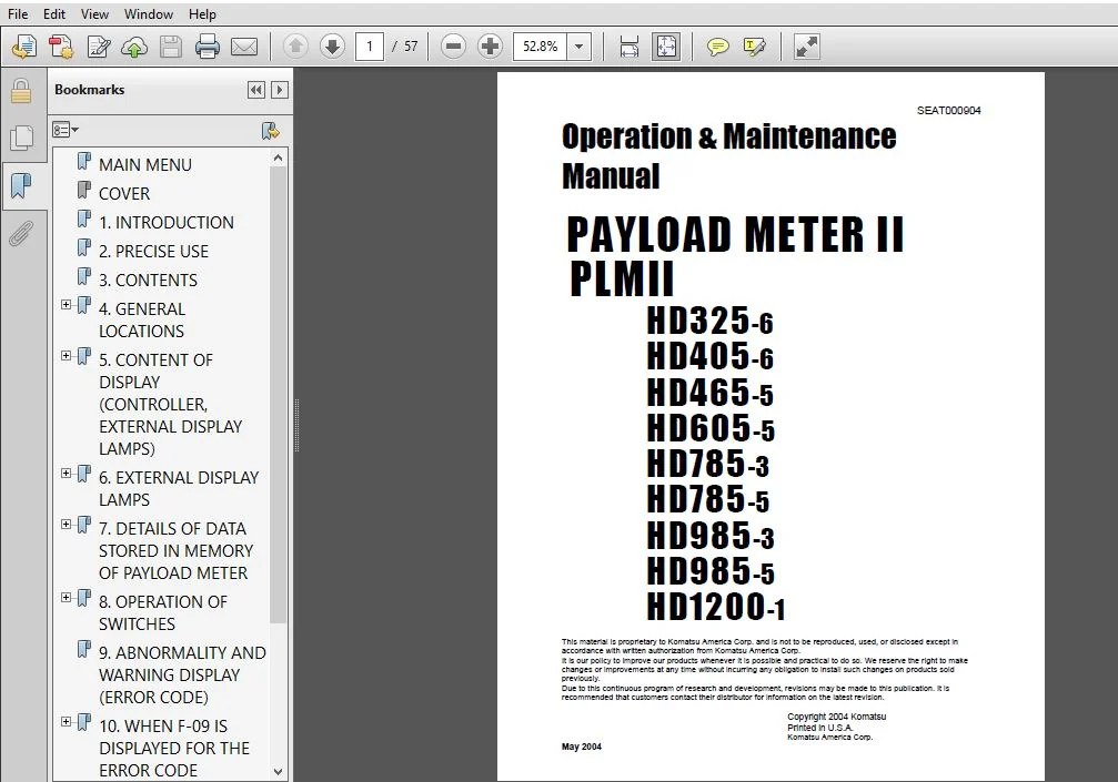
KOMATSU PLMII HD325-6 HD405-6 HD465-5 HD605-5 HD785-3 HD785-5 HD985-3 HD985-5 HD1200-1 PAYLOAD METER II OPERATION & MAINTENANCE MANUAL (SEAT000904) – PDF DOWNLOAD
Original price was: $71.95.$28.95Current price is: $28.95.
- KOMATSU PLMII HD325-6 HD405-6 HD465-5 HD605-5 HD785-3 HD785-5 HD985-3 HD985-5 HD1200-1 PAYLOAD METER II OPERATION & MAINTENANCE MANUAL
- PUBLICATION NUMBER:SEAT000904
Description
KOMATSU PLMII HD325-6 HD405-6 HD465-5 HD605-5 HD785-3 HD785-5 HD985-3 HD985-5 HD1200-1 PAYLOAD METER II OPERATION & MAINTENANCE MANUAL (SEAT000904)
KOMATSU PLMII HD325-6 HD405-6 HD465-5 HD605-5 HD785-3 HD785-5 HD985-3 HD985-5 HD1200-1 PAYLOAD METER II OPERATION & MAINTENANCE MANUAL (SEAT000904) – PDF DOWNLOAD:
IMAGE PREVIEW:
DESCRIPTION:
KOMATSU PLMII HD325-6 HD405-6 HD465-5 HD605-5 HD785-3 HD785-5 HD985-3 HD985-5 HD1200-1 PAYLOAD METER II OPERATION & MAINTENANCE MANUAL (SEAT000904)
- The signals from the pressure sensors, clinometer (not installed on 60°C specification machine), body float detection, and neutral detection are input to the payload meter. These signals are processed by the built-in micro computer, the payload is calculated and dis- played on the panel. At the same time, the external display lamps show the loading condition.
- The payload meter always carries out self diagnosis of this system, and if any abnormality or warning is generated, it displays the details. Using the control switches on the payload meter, it is possible to display various data, such as the total payload from a certain time, the overall number of cycles, or the abnormalities and warnings that are now being generated or have occurred and have already been corrected.
- The payload meter automatically stores in memory various operating data for the dump truck such as the payload, time, distance, travel speed for each cycle, the date and time that the engine was started and stopped, the date and time of abnormalities or warnings that occurred or were canceled, and the total payload and the overall number of cycles from a certain time.
- These automatically recorded data are retained even when the power is switched off, so if a personal computer is connected to the payload meter through the connection port for the communications cable inside the cab, it is possible to send (download) the data later to a personal computer using cable communication (ANSI/EIA RS—232C).
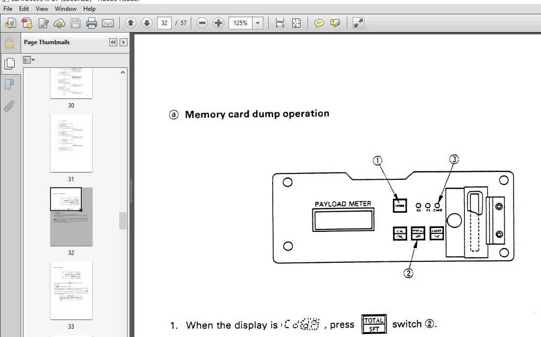
- In addition, based on these data, it is possible to display the operation data on the screen of the computer, to print out the data, or to convert the data for use with Lotus 1-2-3 or EXCEL. It is also possible to set a memory card in the payload meter and to write the various data to the memory card. This memory card can then be used to load the data into a personal computer and to carry out the same data processing that is available using cable communi- cations.
TABLE OF CONTENTS:
KOMATSU PLMII HD325-6 HD405-6 HD465-5 HD605-5 HD785-3 HD785-5 HD985-3 HD985-5 HD1200-1 PAYLOAD METER II OPERATION & MAINTENANCE MANUAL (SEAT000904)
MAIN MENU............................................................................. 0
COVER................................................................................. 1
1. INTRODUCTION....................................................................... 2
2. PRECISE USE........................................................................ 3
3. CONTENTS........................................................................... 4
4. GENERAL LOCATIONS.................................................................. 5
	4.1 FRONT FACE OF CONTROLLER...................................................... 5
	4.2 LEFT FACE OF CONTROLLER....................................................... 6
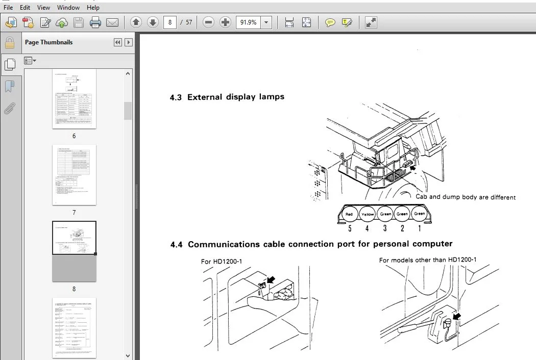
	4.3 EXTERNAL DISPLAY LAMPS........................................................ 8
	4.4 COMMUNICATIONS CABLE CONNECTION PORT FOR PERSONAL COMPUTER.................... 8
5. CONTENT OF DISPLAY (CONTROLLER, EXTERNAL DISPLAY LAMPS)............................ 9
	5.1 WHEN POWER IS ON.............................................................. 9
	5.2 DISPLAY DURING NORMAL OPERATIONS..............................................10
6. EXTERNAL DISPLAY LAMPS.............................................................14
	6.1 DISPLAY LEVEL FOR LAMPS.......................................................14
	6.2 ESTIMATE DISPLAY..............................................................15
7. DETAILS OF DATA STORED IN MEMORY OF PAYLOAD METER..................................16
	7.1 CYCLE DATA....................................................................17
	7.2 ENGINE ON/OFF DATA............................................................18
	7.3 ABNORMALITY, WARNING DATA.....................................................19
	7.4 TOTAL PAYLOAD, OVERALL NUMBER OF CYCLES DATA..................................20
	7.5 OTHER DATA....................................................................20
8. OPERATION OF SWITCHES..............................................................21
	8.1 CARRYING OUT CALIBRATION......................................................22
	8.2 FORCED DISPLAY OF TOTAL PAYLOAD AND OVERALL NUMBER OF CYCLES..................23
	8.3 OPERATOR CHECK MODE...........................................................27
	8.4 DIMMING LIGHTS ON MONITOR DISPLAY.............................................42
	8.5 ADJUSTING BUZZER SOUND LEVEL..................................................42
	8.6 SETTING MASS UNIT.............................................................42
	8.7 SETTING FORCED PROHIBITION FOR SWITCHES.......................................42
	8.8 SERVICE CHECK MODE............................................................43
9. ABNORMALITY AND WARNING DISPLAY (ERROR CODE).......................................44
10. WHEN F-09 IS DISPLAYED FOR THE ERROR CODE (PROCEDURE FOR REPLACING BATTERY).......52
	10.1 REPLACING BATTERY............................................................52
	10.2 AFTER REPLACING THE BATTERY, DO AS FOLLOWS...................................54
11. OPERATION IF F-CAL IS DISPLAYED AS AN ERROR CODE OR THE CONTROLLER IS REPLACED....55
PLEASE NOTE:
⦁ This is not a physical manual but a digital manual – meaning no physical copy will be couriered to you. The manual can be yours in the next 2 mins as once you make the payment, you will be directed to the download page IMMEDIATELY.
⦁ This is the same manual used by the dealers inorder to diagnose your vehicle of its faults.
⦁ Require some other service manual or have any queries: please WRITE to us at [email protected]



