Komatsu PW148-11 Wheeled Excavator Shop Manual VENBM68001 PDF
$37.95
Komatsu PW148-11 Wheeled Excavator Shop Manual VENBM68001 – PDF DOWNLOAD
MACHINE MODEL SERIAL NUMBER
PW148-11 H55051 AND UP
Description
Komatsu PW148-11 Wheeled Excavator Shop Manual VENBM68001 – PDF DOWNLOAD
FILE DETAILS:
Komatsu PW148-11 Wheeled Excavator Shop Manual VENBM68001 – PDF DOWNLOAD
Language : English
Pages : 1086
Downloadable : Yes
File Type : PDF
IMAGES PREVIEW OF THE MANUAL:
TABLE OF CONTENTS:
Komatsu PW148-11 Wheeled Excavator Shop Manual VENBM68001 – PDF DOWNLOAD
MACHINE MODEL SERIAL NUMBER
PW148-11 H55051 AND UP
VENBM68001 PW148-11 1
FOREWORD 5
Safety 5
Important safety notice 5
General precautions 5
Preparations for work 5
Precautions during work 6
General 7
General 7
Structure and function 7
Testing, adjusting and troubleshooting 7
Disassembly and assembly 7
Maintenance standard 7
How to read the shop manual 8
Volumes 8
Distribution and updating 8
Filing method 8
Revised edition mark 8
Revisions 8
Symbols 8
Hoisting instructions 9
Hoisting 9
Wire Ropes 9
Coating materials 10
Standard tightening torque 12
Standard tightening torque of bolts and nuts 12
Tightening torque of hose nuts 13
Tightening torque of split flange bolts 13
Tightening torques for hoses (taper seal type and face seal type) 13
Tightening torque for 107 engine series (bolts and nuts) 14
Tightening torque for 107 engine series (eye joints) 14
Tightening torque for 107 engine series (tapered screws) 14
Electric wire code 15
Classification by thickness 15
Classification by color and code 15
Conversion tables 16
Method of using the conversion table 16
Units 22
GENERAL 23
Specification dimension drawings 24
Dimensions 24
Working ranges 26
Working range: 1-piece boom 26
Working range: 2-piece boom 27
Weight table 31
1-piece boom 32
2-piece boom 33
Fuel, coolant and lubricants 34
STRUCTURE AND FUNCTION 35
Abbreviation list 38
List of abbreviations used in the text 38
List of abbreviations used in the circuit diagrams 42
UREA SCR system 43
Layout drawing of UREA SCR system 43
Detailed drawing of SCR assembly 46
Detailed drawing of AdBlue/DEF tank 47
UREA SCR system diagram 48
Function of UREA SCR system 49
Function of AdBlue/DEF system 50
AdBlue/DEF injection function 50
AdBlue/DEF purge function 51
Function of AdBlue/DEF thawing and preventing from freezing 51
Inducement strategy 52
Inducement strategy when the AdBlue/DEF level in the tank becomes low (for north America) 53
Inducement strategy when abnormality is found in the UREA SCR system devices (for north America) 54
Inducement strategy when abnormality is found in the KDOC system by the IREA SCR system (for north America) 56
Function of temporary restoration from inducement (for north America) 58
Inducement strategy for abnormality recurrence within 40 hours (for north America) 59
Inducement strategy when the AdBlue/DEF level in the tank becomes low (for European Union) 60
Inducement strategy when abnormality is found in the AdBlue/DEF quality or in the UREA SCR system devices (for European Union) 62
Inducement strategy when abnormality is found in the KDOC system by the IREA SCR system (for Europan Union) 64
Inducement strategy when abnormality is found in the EGR system by the IREA SCR system devices (foR European Union) 66
Function of temporary restoration from inducement (for European Union) 67
Inducement strategy for abnormality recurrence within 40 hours (for European Union 68
Component parts of UREA SCR system 69
AdBlue/DEF MIXING TUBE 69
SCR assembly 70
Structure of UREA SCR assembly 70
AdBlue/DEF tank 72
Structure of AdBlue/DEF tank 72
AdBlue/DEF tank sensor 73
Function of AdBlue tank sensor 73
AdBlue/DEF pump 74
AdBlue/DEF injector 75
AdBlue/DEF hose 76
AdBlue/DEF tank heating valve 77
BOOT-UP system 78
Layout drawing of BOOT-UP system 78
System operating lamp system 79
System operating lamp system diagram 79
Function of system operating lamp system 79
Battery disconnect switch 80
Function of battery disconnect switch 80
Engine system 82
Layout drawing of engine system 82
Function of engine system 83
Engine control system 83
Engine control system diagram 83
Function of engine control system 84
Auto-deceleration system 87
Auto-deceleration system diagram 87
Engine automatic warm-up system 89
Engine automatic warm-up system diagram 89
Function of engine automatic warm-up system 90
Overheat prevention system 91
Overheat prevention system diagram 91
Function of overheat prevention system 92
Turbocharger protection system 93
Turbocharger protection system diagram 93
Function of turbocharger protection system 94
Automatic idle stop system 95
Automatic idle stop system diagram 95
Function of automatic idle stop system 95
Abrupt engine stop is detected 98
Component parts of engine system 99
Structure of VGT 99
EGR system 102
Layout drawing of EGR system 102
Function of EGR system 102
Circuit diagram of EGR system 103
Operation of EGR system 103
EGR valve 104
Structure of EGR valve 104
General view and sectional view 104
Operation of EGR valve 105
EGR cooler 106
Structure of EGR cooler 106
General view and sectional view 106
Detailed drawing of flat tube 107
Operation of EGR cooler 107
KCCV system 108
Layout drawing of KCCV system 108
KCCV ventilator 110
Structure of KCCV ventilator 110
Function of KCCV ventilator 110
Operation of KCCV ventilator 111
CDR valve 111
KDOC 112
Structure of KDOC 112
Function of KDOC 113
Types of regeneration functions 113
Cooling system 116
Layout drawing of cooling system 116
Specifications of cooling system 117
Fan speed control system of fan clutch 118
Engine output control system of fan clutch 120
Engine output control system diagram of fan clutch 120
Function of engine output control system of fan clutch 121
Component parts of cooling system 122
Fan clutch 122
Power train 124
Swing circle 126
Specifications 126
Swing machinery & motor 127
Specification 128
Operation of swing lock 129
Relief valve portion 130
Operation 130
Undercarriage 132
Transmission 134
Specifications 135
Function 137
Trailer 138
Calculation of maximum coupling Load 138
Automatic trailer coupling for blade 139
Functional check 139
Possible faults in the coupling 140
Wear limits 141
Automatic Trailer Coupling For Outrigger 143
Functional check 143
Height Adjustment Components 144
Functional check 144
Possible faults in the coupling 145
Wear limits 147
Inspection 149
2nd Auxiliary circuit in the undercarriage 150
Function 150
Specifications 151
PW148-11: Schematic of auxiliary circuit 151
Hydraulic quick coupler 152
Schematic 152
Operation 153
Hydraulic quick coupler solenoid valve 153
Specification 153
Quick coupler error logic 154
Full hydraulic quick coupler 155
Travel motor 157
Function 158
Operation of travel motor 159
Clutch control circuit 161
Function 162
Axle 163
Outline 163
Suspension lock cylinder 166
Specifications 166
Structure and function 166
Circuit 167
Axle oscillation 167
Braking system 168
Structure and function 169
Gear pump 170
Specifications 170
Function 170
Priority valve 172
Specification 172
Function 172
Power brake valve 174
Specifications 175
Function 175
Accumulator for brake valve 176
Specifications 176
Structure and function 176
Steering system 177
Structure and function 177
Joystick steering system 178
Structure and function 179
Steering column JSS 180
Specifications 181
Steering column STD 183
Steering column JSS 184
Orbitrol valve STD 185
Specifications 185
Structure and function 185
Orbitrol valve JSS 186
Specifications 186
Structure and function 186
Hydraulic equipment layout drawings 188
Hydraulic circuit diagram 190
Hydraulic tank 191
Specifications 191
Hydraulic pump 192
Function 194
Structure 194
Operation 195
LS valve 197
PC valve 198
Function 199
Operation 200
1 LS valve 200
2 PC valve 204
LS(PC)-EPC valve 211
Function 212
Operation 212
Pilot pressure control (PPC) system 214
Function 215
Operation 215
Control main valve 216
Outline 216
CLSS 231
Outline of CLSS 231
Features 231
Structure 231
Basic Principle 232
Operation for each function and valve 234
Hydraulic circuit diagram and name of valves 234
1 Unload valve 236
Function 236
Operation 236
Operation 237
Operation 238
2 Introduction of LS pressure 239
Work equipment valve 239
Function 239
Operation 239
3 LS bypass plug 240
Outline 240
Operation 240
4 Pressure compensation valve 241
Function 241
Operation 242
5 Area ratio of pressure compensation valve 243
Function 243
6 Boom regeneration circuit 244
Function 244
Operation 244
Function 245
Operation 245
7 Arm regeneration circuit 246
Function 246
Operation 246
Function 247
Operation 247
8 Swing bleeding valve 248
Function 248
Operation (In fine control operation) 249
9 LS select valve 250
Function 250
Operation 250
Centre swivel joint 251
Travel PPC pedal 252
Work equipment – Swing PPC valve 254
Operation 256
Solenoid valve block with integrated ATT – EPC 258
ON / OFF Solenoid valves (3 way valve) 260
Operation 260
ON / OFF Solenoid valves (4 way valve) 262
Operation 262
Hi/ Lo Solenoid valve (4 way valve) 264
Attachment PPC valve 266
Function 267
Operation 267
Undercarriage solenoid valve block 269
Boom/Outrigger schematic 270
Undercarriage attachment schematic 271
Proportional attachment control 272
Proportional attachment schematic 273
Bucket to 2ATT 274
Function 274
Bucket to 2 ATT valve 275
Boom safety valve 276
Operation 277
Boom floating 278
PPC pressure reduction/ Boom floating logic 278
Hydraulic cylinder 284
Boom cylinder 284
Arm cylinder 284
Bucket cylinder 284
Adjust cylinder 285
Outrigger cylinder 286
Function 287
Dozer cylinder 288
Function 289
Work equipment 290
Work equipment 291
1 Dimension of arm 292
2 Dimension of bucket 294
Tool control 296
Tool control schematic (detail from hydraulic diagram) 297
ECSS 298
ECSS Logic 298
ESS Hydraulic Schematic 300
ECSS Accumulator position 301
ECSS Valve 302
ECSS Hydraulic diagram 303
Breaker return valve 304
Function 304
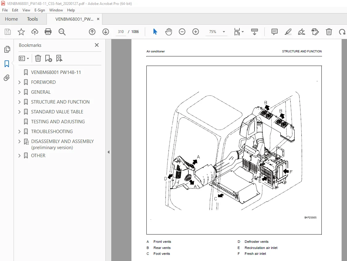
Air conditioner 308
Air conditioner component 308
Specifications of air conditioner 311
Electrical wiring diagram 312
Electrical system 313
Engine control 313
1 Operation of System 313
2 Component 314
Engine controller 315
Structure of engine controller 315
General view 315
Input and output signals of engine controller 315
Machine control system diagram 324
1 Engine and pump control function 325
Function 326
Function 330
Function 332
Function 334
Operation 335
Function 336
Function 340
Function 342
Function 345
Specifications 346
Function 346
Function 347
Operation 347
Machine monitor system 351
Function of machine monitor 353
Monitor display 358
Monitor items and display 360
Caution monitor 362
Pilot monitor 366
Monitor switches 370
Declaration of switch function on keypad 371
Guidance icon and function switch 373
Operator mode function 376
Service mode function of machine monitor 378
KOMTRAX system 380
KOMTRAX terminal 381
Structure of KOMTRAX terminal 381
Function of KOMTRAX terminal 381
KomVision system 383
Layout drawing of KomVision system 383
Chassis part 383
Around cab and floor 384
KomVision system diagram 384
Function of KomVision system 385
KomVision controller 386
Structure of KomVision controller 386
Structure of KomVision camera 390
Overload warning device 391
Outline 391
Function 391
Structure 391
Sensor 392
Ambient pressure sensor 394
Charge (boost) pressure and temperature sensor 395
Coolant temperature sensor 396
Ne (crankshaft) speed sensor 396
Bkup (camshaft) speed sensor 397
Common rail pressure sensor 397
Exhaust manifold pressure sensor 398
EGR orifice temperature sensor 398
Variable flow turbocharger motor (with built-in position sensor) 399
EGR valve (with built-in position sensor) 400
EGR valve lift sensor 401
KVGT speed sensor 402
KVGT position sensor 403
Mass air flow and temperature sensor 404
KDOC inlet temperature sensor 405
KDOC outlet temperature sensor 405
Crankcase pressure sensor 406
Engine oil level sensor 407
Fuel level sensor 408
WIF (Water-In-Fuel detection) sensor 409
Coolant level sensor 410
Hydraulic oil temperature sensor 411
Air cleaner clogging sensor 411
Overload Caution sensor 412
Swing proximity sensor 413
Brake sensors 413
Brake accumulator low pressure sensor (CN-P60) 414
Brake stop light sensor (CN-S19) 414
Service brake pressure sensor (CN-S40) 414
Service brake pressure sensor (CN-P62) 414
Park brake pressure sensor (CN-P61) 415
PPC pressure sensors 415
DPF-SCR Area 416
Main valve sensor 417
PPC levers 418
LH PPC lever 418
RH PPC lever 419
1st attachment circuit hydraulic performance (main valve bypassed) 420
Travel system 421
Travel circuit 421
Travel Motor Performance 422
Auto-grease pump 424
Overview 425
Display and control unit 425
LED-display 426
Push buttons 426
Three-digit LED display 427
Check central lubrication system, fill up grease 428
Lubrication diagrams 429
Auto-grease pump with one-piece boom 429
Auto-grease pump with two-piece boom 430
Manual system one-piece boom 431
Manual system two-piece boom 432
STANDARD VALUE TABLE 433
Engine and cooling system 466
Test engine speed 466
Method for testing engine speed 466
Replacing the fan belt 514
Measurement of clearance in swing circle bearing 515
Inspection and adjustment of hydraulic oil pressure in hydraulic circuit for work equipment, swing and travel 516
Measurement 516
Adjustment 517
Inspection and adjustment of control circuit oil pressure 519
Measurement 519
Procedure for pressure reducing adjustment 520
Inspection and adjustment of pump PC (valve inlet) control oil pressure 521
Measurement 521
Adjustment 523
Inspection and adjustment of pump LS differential pressure 524
Measurement 524
Adjustment 526
Measurement of solenoid valve output pressure 527
Checking Proportional Control PPC Circuit 529
Adjustment of work equipment and swing PPC valve 530
Measuring and adjusting quick coupler control valve output pressure 531
Testing travel motor relief pressure 532
Measuring travel motor relief pressure 532
Testing propshaft speed 533
Measuring rotating speed of propshaft 533
Testing transmission clutch control circuit 534
Description 534
Inspection of locations of hydraulic drift of work equipment 536
Release of remaining pressure in hydraulic circuit 538
Measurement of oil leakage 539
Air bleeding of various parts 542
Inspection procedures for diode 545
Electrical system 546
Special function of monitor panel 546
Service mode 556
Method for checking pre-defined monitoring information 559
Table of self-define monitoring 573
Abnormality record menu 584
Method for confirming maintenance record 589
Method For Operating Maintenance Mode Setting 590
Method for operating phone number entry setting 594
Diagnostic tests menu 607
Adjustment menu 616
KOMTRAX settings menu 624
Method for starting up KOMTRAX terminal 628
Inspection and adjustment of ECSS (ACCU pressure) 633
Maintenance 633
Inspection and adjustment of Tool control 636
Changing the lubrication interval times 642
Adjust rearview camera angle 644
Method for adjusting rear view camera angle 644
Adjust KomVision camera angle 646
Tools for adjusting KomVision camera angle 646
Method for adjusting KomVision camera angle 647
Angle adjustment method for front R H camera, rear R H camera, and rear L H camera 647
Angle adjustment method for rear camera 648
Adjust KomVision related items 650
Setting of KomVision (main setting) 651
Method for setting KomVision (main setting) 651
Setting of KomVision (camera setting) 653
Method for setting KomVision (camera setting) 653
Setting of KomVision (camera calibration) 653
Method for setting of KomVision (camera calibration) 654
TESTING AND ADJUSTING 463
TROUBLESHOOTING 665
Troubleshooting 665
Troubleshooting by failure code (Display of code) 666
Failure code table (Display of code) 666
Failure code [DB30KR] – Joystick steering controller malfunction 685
Failure code [DA22KK] – Pump solenoid power low error 686
Failure code [DCS2KK] – Machine controller solenoid power voltage low error 688
Failure code [DWB5KY] – Hot short circuit in 4th outrigger solenoid 690
DISASSEMBLY AND ASSEMBLY (preliminary version) 693
FRONT AXLE 693
Note 694
Table of contents 695
Preface 697
General 698
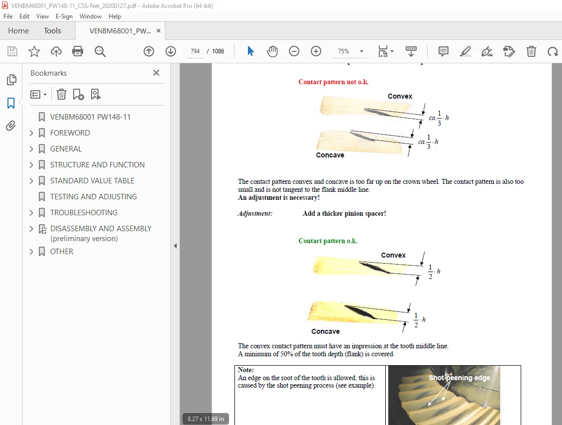
Examples of gear-tooth contact pattern for the Gleason gear-tooth system 700
Conversion table 704
Denomination of standard dimensions 0
Tightening torques for screws 706
Special tools 707
Commercial tools 719
1 Disassembly steering 724
2 Disassembly output 727
2 1 Disassembly planetary carrier 727
2 2 Disassembly brake 728
2 3 Disassembly hub 730
2 4 Disassembly knuckle housing 731
2 5 Disassembly output assy 733
3 Disassembly input 734
4 Disassembly differential 738
4 1 DZ-500 and D-500 738
4 2 DZ-750 and D-750 741
5 Reassembly differential 743
5 1 DZ-500 and D-500 743
5 2 DZ-750 and D-750 747
6 Reassembly input 751
6 1 Install input pinion 751
6 1 1 Determine thickness of the shim to obtain a correct contact pattern 751
6 1 2 Setting of rolling torque of the input pinion bearing 753
6 2 Setting instructions for bevel gear set backlash and bearing rolling torque of the differential bearing 755
6 2 1 Check of backlash pattern of the bevel gear set 757
6 3 Mount shaft seal ring (input flange) 759
7 Reassembly output 760
7 1 Preassembly axle housing 760
7 2 Reassembly knuckle housing 761
7 3 Reassembly hub 765
7 4 Reassembly disk brake 767
7 4 1 Make leakage test of multi-disk brake 770
7 4 2 Adjust and check piston stroke 771
7 5 Reassembly planetary carrier 773
7 6 Reassembly output assy 774
7 7 Reassembly pivot bearing 775
8 Reassembly steering 776
8 1 Preassemble steering 776
8 2 Mount steering 779
8 3 Track setting and checking 781
8 4 Steering angle setting 782
8 5 Check leakage of steering 783
REAR AXLE 784
Note 785
Table of contents 786
Preface 788
General 789
Examples of gear-tooth contact pattern for the Gleason gear-tooth system 791
Conversion table 795
Denomination of standard dimensions 796
Tightening torques for screws 797
Special tools 798
Commercial tools 805
1 Disassembly of output 810
1 1 Disassembly of planetary carrier 810
1 2 Disassembly of brake 811
1 3 Disassembly of hub 813
1 4 Disassembly of output assy 815
2 Disassembly of input 816
2 1 Version with HL transmission 816
2 2 Standard version 818
3 Disassembly differential 821
3 1 DZ-500 und D-500 821
3 2 DZ-750 und D-750 824
4 Reassembly differential 826
4 1 DZ-500 und D-500 826
4 2 DZ-750 und D-750 830
5 Reassembly of input 834
5 1 Version with HL-transmission 834
5 1 1 Determination of shims for setting the bearing rolling torque (differential bearing) and the backlash (bevel gear set) 834
5 2 Standard version (without HL transmission) 839
5 2 1 Reinstallation of input pinion 839
5 2 2 Adjust backlash of crown wheel set and bearing rolling torque of differential bearing 842
5 2 3 Fitting of shaft seal ring (input flange) 846
6 Reassembly of output 847
6 1 Reassembly of hub carrier 847
6 2 Reassembly of hub (Hub bearing SET-RIGHT) 847
6 3 Reassembly of multi-disk brake 850
6 3 1 Leakage test of multi-disk brake 853
6 3 2 Adjustment and check of piston stroke 854
6 4 Reassembly of planetary carrier 855
6 5 Reassembly of output assy 856
TRANSMISSION 857
Note 858
Table of contents 859
Preface 861
General 862
Conversion table 864
Denomination of standard dimensions 865
Torque limits for screws 866
Special tools 867
Commercial tools 876
1 Separate HL-Transmission from axle housing 881
2 Disassembly – Brake/Clutch/Planetary carrier 882
2 1 Lubrication pump and shift interlock 882
2 1 1 Version “Lubrication pump” 882
2 2 Speed sensor 883
2 3 Emergency release (Parking Brake) 883
2 4 Input housing and modulation valve 884
2 5 Brake and clutch 885
2 6 Planetary carrier 891
3 Disassembly – Output 894
3 1 Version “Axle attachment” 894
3 2 Version “Separate Installation” 898
4 Reassembly – Output 901
4 1 Version “Axle attachment” 901
4 1 1 Determine shim for pinion gap 903
4 1 2 Determine adjusting ring for rolling torque/pinion bearing 907
4 1 3 Check rolling torque of pinion bearing 908
4 1 4 Shaft seal output flange 909
4 1 5 Check the pinion gap 910
4 2 Version “Separate installation” 911
4 2 1 Shaft seal output flange 914
5 Reassembly – Brake/Clutch/Planety carrier 917
5 1 Planetary carrier 917
5 2 Brake and clutch 921
5 2 1 Disc components brake and clutch 923
5 2 1 1 Version “HL-290” 923
5 2 1 2 Version “HL-270” 0
5 2 1 3 Version “HL-250” 923
5 2 2 Adjust and check the disc clearance/piston stroke of brake and clutch 925
5 3 Install modulation valve and input housing 932
5 4 Emergency release (Parking brake) 934
5 4 1 Check emergency release for leak tightness 935
5 4 2 Check the multi-disk brake and multi-disc clutch for leak tightness as well as closing pressure 936
5 5 Speed sensor 937
5 6 Lubrication pump/shift interlock 937
6 Disassembly – Lubrication pump/shift interlock and valve block 939
6 1 Version “with” lubrication pump 939
6 2 Version “with” hydr shift interlock 942
6 3 Disassembly valve block 945
7 Reassembly Lubrication pump 947
8 Reassembly shift interlock 953
9 Valve block (shifting low gear – high gear) 961
10 Mount HL-Transmission to axle 962
OTHER 963
Hydraulic circuit diagram 967
Hydraulic circuit diagram (1/3) 967
Hydraulic circuit diagram (2/3) 969
Hydraulic circuit diagram (3/3) 971
Wiring circuit diagram 973
Contents 973
1-0 Power Supply 975
1-1 Grounding 976
1-2 Model Select 977
2-0 Engine PW180 978
2-1 Engine PW180 979
2-2 Engine PW48, PW160 980
2-3 Engine PW48, PW160 981
2-4 Engine Power Supply, Air Intake 982
2-5 Engine Start 983
2-6 2nd ENGINE STOP, OPERATING LAMP 984
2-7 ADBLUE/DEF DATALINK 985
2-8 ADDBLUE/DPF POWER 986
3-0 REFUELING SYSTEM, FUEL DIAL 987
3-1 BRAKE 988
3-2 EPC 989
3-3 CRUISE CONTROL 990
3-4 TRAVEL 991
3-5 SUS-LOCK, SPEEDSNR, JOYSTICK POTI 992
3-6 SENSORS ENGINE & OIL 993
4-0 QUICK COUPLER, PRESSURE SENSOR 994
4-1 PPC REDUCTION, FLOATING, PRESSURE SENSOR 995
4-2 SWING LOCK, PRESSURE SENSOR, JOYSTICK SW 996
4-3 BUCKET/2ATT SWITCHING 997
5-0 LOWER ATTACHMENTS 998
5-1 ROTO-TILT 999
5-2 BOOM/STABILISER, AUXILARY CIRCUIT, BREAKER 1000
6-0 ROAD LIGHT 1001
6-1 INDICATOR, SIDE LIGHT, STOP LIGHT 1002
6-2 ARM MARKER LIGHT + QC SIGNAL BOOM 1003
6-3 BEACON, TRAILER (OPT) 1004
6-4 WORKLAMP 1005
6-5 WORKLAMP 1006
6-6 CAMERA SW, SERVICE-CON , KOMTRAX, KOMNET 1007
6-7 KOMVISION 1008
7-0 AIR CONDITION, HEATED MIRROR 1009
7-1 RADIO, 12V, CIGAR LIGHTER, ROOM LAMP 1010
7-2 PPC-LOCK, STARTER CUT, SEAT 1011
7-3 ID-KEY 1012
7-4 HORN, TRAVEL ALARM 1013
7-5 WIPER 1014
8-0 CLS 1015
9-0 JOYSTICK STEERING 1016
10-0 FAN CLUTCH, TOOL CONTROL 1017
11-0 ECSS 1018
Harness Summary 1019
Harness Summary 1020
Connector List 1021
Connector List 1022
Connector List 1023
Connector List 1024
Connector List 1025
Connector List 1026
Connector List 1027
Pin Location List 1028
Pin Location List 1029
Pin Location List 1030
Pin Location List 1031
Pin Location List 1032
Pin Location List 1033
Pin Location List 1034
Pin Location List 1035
Pin Location List 1036
Pin Location List 1037
Pin Location List 1038
Pin Location List 1039
Pin Location List 1040
Pin Location List 1041
Pin Location List 1042
Pin Location List 1043
Pin Location List 1044
Pin Location List 1045
Pin Location List 1046
Pin Location List 1047
Pin Location List 1048
Pin Location List 1049
Pin Location List 1050
PinLocation List 1051
PinLocation List 1052
PinLocation List 1053
Pin Location List 1054
Pin Location List 1055
Pin Location List 1056
Pin Location List 1057
Pin Location List 1058
Pin Location List 1059
Pin Location List 1060
Pin Location List 1061
Pin Location List 1062
Pin Location List 1063
Pin Location List 1064
Pin Location List 1065
Pin Location List 1066
Pin Location List 1067
Pin Location List 1068
PARTS LIST 1069
PARTS LIST 1070
PARTS LIST 1071
PARTS LIST 1072
PARTS LIST 1073
Connector diagram 1075
Connector diagram 1/10 1075
Connector table for revolving frame harness 1 1075
Connector diagram 2/10 1076
Connector table for revolving frame harness 2 1076
Connector diagram 3/10 1077
Connector table for operator‘s cab wiring harness (Part 1/2) 1077
Connector diagram 4/10 1078
Connector table for operators cab wiring harness (Part 2/2) 1078
Connector diagram (5/10) 1079
Connector table switch group 1079
Connector diagram (6/10) 1080
Connector table steering 1080
Connector diagram (7/10) 1081
Connector table various wiring harness 1081
Connector diagram (8/10) 1082
Connector table optionally wiring harness (Part 1/3) 1082
Connector diagram (9/10) 1083
Connector table optionally wiring harness (Part 2/3) 1083
Connector diagram (10/10) 1084
DESCRIPTION:
Komatsu PW148-11 Wheeled Excavator Shop Manual VENBM68001 – PDF DOWNLOAD
MACHINE MODEL SERIAL NUMBER
PW148-11 H55051 AND UP
GENERAL PRECAUTIONS :
Mistakes in operation are extremely dangerous. Read the OPERATION & MAINTENANCE MANUAL carefully BEFORE operating the machine.
PREPARATIONS FOR WORK:
PRECAUTIONS DURING WORK :
S.V 30/12/24


