Komatsu PW148-11E0 PW158-11E0 Wheeled Excavator Shop Manual VENBM71001 PDF
$39.95
Komatsu PW148-11E0 PW158-11E0 Wheeled Excavator Shop Manual VENBM71001 – PDF DOWNLOAD
MACHINE MODEL SERIAL NUMBER
PW148-11E0 H56051 AND UP
PW158-11E0 H58551 AND UP
Description
Komatsu PW148-11E0 PW158-11E0 Wheeled Excavator Shop Manual VENBM71001 – PDF DOWNLOAD
FILE DETAILS:
Komatsu PW148-11E0 PW158-11E0 Wheeled Excavator Shop Manual VENBM71001 – PDF DOWNLOAD
Language : English
Pages : 2372
Downloadable : Yes
File Type : PDF
IMAGES PREVIEW OF THE MANUAL:
TABLE OF CONTENTS:
Komatsu PW148-11E0 PW158-11E0 Wheeled Excavator Shop Manual VENBM71001 – PDF DOWNLOAD
MACHINE MODEL SERIAL NUMBER
PW148-11E0 H56051 AND UP
PW158-11E0 H58551 AND UP
VENBM71001 PW148-11E0, PW158-11E0 1
FOREWORD 5
Safety 5
Important safety notice 5
General precautions 5
Preparations for work 5
Precautions during work 6
General 7
General 7
Structure and function 7
Testing, adjusting and troubleshooting 7
Disassembly and assembly 7
Maintenance standard 7
How to read the shop manual 8
Volumes 8
Distribution and updating 8
Filing method 8
Revised edition mark 8
Revisions 8
Symbols 8
Hoisting instructions 9
Hoisting 9
Wire Ropes 9
Coating materials 10
Standard tightening torque 12
Standard tightening torque of bolts and nuts 12
Tightening torque of hose nuts 13
Tightening torque of split flange bolts 13
Tightening torques for hoses (taper seal type and face seal type) 13
Tightening torque for 107 engine series (bolts and nuts) 13
Tightening torque for 107 engine series (eye joints) 14
Tightening torque for 107 engine series (tapered screws) 14
Electric wire code 15
Classification by thickness 15
Classification by color and code 15
Conversion tables 16
Method of using the conversion table 16
Units 22
GENERAL 23
Specification dimension drawings 24
Dimensions PW148-11E0 24
Dimensions PW158-11E0 26
Working ranges 28
Working range: 1-piece boom 28
Working range: 2-piece boom 29
Weight table 34
1-piece boom 36
2-piece boom 37
Fuel, coolant and lubricants 38
STRUCTURE AND FUNCTION 41
Abbreviation list 44
List of abbreviations used in the text 44
List of abbreviations used in the circuit diagrams 48
UREA SCR system 50
Layout drawing of UREA SCR system 50
Detailed drawing of SCR assembly 52
Detailed drawing of AdBlue/DEF tank 53
UREA SCR system diagram 54
Function of UREA SCR system 55
Function of AdBlue/DEF system 56
AdBlue/DEF injection function 56
AdBlue/DEF purge function 57
Function of AdBlue/DEF thawing and preventing from freezing 58
Inducement strategy 59
Inducement strategy when the AdBlue/DEF level in the tank becomes low (for European Union) 60
Inducement strategy when abnormality is found in the AdBlue/DEF quality or in the UREA SCR system devices (for European Union) 62
Inducement strategy when abnormality is found in the KDPF system by the UREA SCR system devices (for European Union) 64
Inducement strategy for abnormality recurrence within 40 hours 65
Component parts of UREA SCR system 66
SCR assembly 66
Structure of SCR assembly 66
AdBlue/DEF tank 68
Structure of AdBlue/DEF tank 68
AdBlue/DEF tank sensor 69
Function of AdBlue/DEF tank sensor 69
AdBlue/DEF pump 70
AdBlue/DEF injector 71
AdBlue/DEF hose 72
AdBlue/DEF tank heating valve 73
BOOT-UP system 74
Layout drawing of BOOT-UP system 74
System operating lamp system 75
System operating lamp system diagram 75
Function of system operating lamp system 75
Battery disconnect switch 76
Function of battery disconnect switch 76
Engine system 78
Layout drawing of engine system 78
Engine control system 79
Engine control system diagram 79
Function of engine control system 80
Auto-deceleration system 83
Auto-deceleration system diagram 83
Engine automatic warm-up system 85
Engine automatic warm-up system diagram 85
Function of engine automatic warm-up system 86
Overheat prevention system 87
Overheat prevention system diagram 87
Function of overheat prevention system 88
Turbocharger protection system 89
Turbocharger protection system diagram 89
Function of turbocharger protection system 90
Automatic idle stop system 91
Automatic idle stop system diagram 91
Function of automatic idle stop system 91
Abrupt engine stop is detected 94
Component parts of engine system 95
Structure of turbocharger 95
Crankcase ventilation system 97
System diagram of crankcase ventilation system 97
Function of crankcase ventilation system 97
Impactor (filterless) 98
Structure of impactor (filterless) 98
Operation of impactor (filterless) 98
Exhaust throttle valve 99
Structure of exhaust throttle valve 99
KDPF 100
Structure of KDPF 100
Function of KDPF 101
Types of regeneration functions 103
Cooling system 105
Layout drawing of cooling system 105
Specifications of cooling system 105
Fan speed control system of fan clutch 106
Engine output control system of fan clutch 108
Engine output control system diagram of fan clutch 108
Function of engine output control system of fan clutch 108
Component parts of cooling system 110
Fan clutch 110
Power train 112
Swing circle 114
Specifications 114
Swing machinery & motor 115
Specification 116
Operation of swing lock 117
Relief valve portion 118
Operation 118
Undercarriage 120
Transmission 122
Specifications 123
Function 125
Trailer 126
Calculation of maximum coupling Load 126
Automatic trailer coupling for blade 127
Functional check 127
Possible faults in the coupling 128
Wear limits 129
Automatic Trailer Coupling For Outrigger 131
Functional check 131
Height Adjustment Components 132
Functional check 132
Possible faults in the coupling 133
Wear limits 135
Inspection 137
2nd Auxiliary circuit in the undercarriage 138
Function 138
Specifications 139
Schematic of auxiliary circuit 139
Hydraulic quick coupler 140
Schematic 140
Operation 141
Hydraulic quick coupler solenoid valve 141
Specification 141
Quick coupler error logic 142
Full hydraulic quick coupler 143
Travel motor 145
Function 146
Operation of travel motor 147
Clutch control circuit 149
Function 150
Axle 151
Outline 151
Suspension lock cylinder 154
Specifications 154
Structure and function 154
Circuit 155
Axle oscillation 155
Braking system 156
Structure and function 157
Gear pump 158
Specifications 158
Function 158
Priority valve 160
Specification 160
Function 160
Power brake valve 162
Specifications 163
Function 163
Accumulator for brake valve 164
Specifications 164
Structure and function 164
Digging brake valve 165
Digging brake controller 166
Steering system 167
Structure and function 167
Joystick steering system 168
Structure and function 169
Steering column JSS 170
Specifications 171
Steering column STD 173
Steering column JSS 174
Orbitrol valve STD 175
Specifications 175
Structure and function 175
Orbitrol valve JSS 176
Specifications 176
Structure and function 177
Hydraulic equipment layout drawings 178
Hydraulic circuit diagram 180
Hydraulic tank 181
Specifications 181
Hydraulic pump 182
Function 184
Structure 184
Operation 185
LS valve 187
PC valve 188
Function 189
Operation 190
1 LS valve 190
2 PC valve 194
LS(PC)-EPC valve 201
Function 202
Operation 202
Pilot pressure control (PPC) system 204
Function 205
Operation 205
Control main valve 206
Outline 206
CLSS 221
Outline of CLSS 221
Features 221
Structure 221
Basic Principle 222
Operation for each function and valve 224
Hydraulic circuit diagram and name of valves 224
1 Unload valve 226
Function 226
Operation 226
Operation 227
Operation 228
2 Introduction of LS pressure 229
Work equipment valve 229
Function 229
Operation 229
3 LS bypass plug 230
Outline 230
Operation 230
4 Pressure compensation valve 231
Function 231
Operation 232
5 Area ratio of pressure compensation valve 233
Function 233
6 Boom regeneration circuit 234
Function 234
Operation 234
Function 235
Operation 235
7 Arm regeneration circuit 236
Function 236
Operation 236
Function 237
Operation 237
8 Swing bleeding valve 238
Function 238
Operation (In fine control operation) 239
9 LS select valve 240
Function 240
Operation 240
Centre swivel joint 241
Travel PPC pedal 242
Work equipment – Swing PPC valve 244
Operation 246
Solenoid valve block with integrated ATT – EPC 248
ON / OFF Solenoid valves (3 way valve) 250
Operation 250
ON / OFF Solenoid valves (4 way valve) 252
Operation 252
Hi/ Lo Solenoid valve (4 way valve) 254
Attachment PPC valve 256
Function 257
Operation 257
Undercarriage solenoid valve block 259
Boom/Outrigger schematic 260
Undercarriage attachment schematic 261
Proportional attachment control 262
Proportional attachment schematic 263
Bucket to 1ATT 264
Function 264
Bucket to 1 ATT valve 265
Boom safety valve 266
Operation 267
Boom floating 268
PPC pressure reduction/ Boom floating logic 268
Hydraulic cylinder 274
Boom cylinder 274
Arm cylinder 274
Bucket cylinder 274
Adjust cylinder 275
Outrigger cylinder 276
Function 277
Dozer cylinder 278
Function 279
Work equipment 280
Work equipment 281
1 Dimension of arm 282
2 Dimension of bucket 284
Tool control 286
Tool control schematic (detail from hydraulic diagram) 287
ECSS 288
ECSS Logic 288
ESS Hydraulic Schematic 290
ECSS Accumulator position 291
ECSS Valve 292
ECSS Hydraulic diagram 293
Breaker return valve 294
Function 294
Air conditioner 298
Air conditioner component 298
Specifications of air conditioner 301
Electrical wiring diagram 302
Electrical system 303
Engine control 303
1 Operation of System 303
2 Component 304
Engine controller 305
Structure of engine controller 305
General view 305
Input and output signals of engine controller 305
Pump controller 310
Machine controller 314
Machine control system diagram 318
1 Engine and pump control function 319
Function 320
Function 324
Function 326
Function 328
Operation 329
Function 330
Function 334
Function 336
Function 339
Specifications 340
Function 340
Function 341
Operation 341
Machine monitor system 345
Function of machine monitor 346
Monitor display 350
Monitor items and display 352
Caution monitor 354
Pilot monitor 358
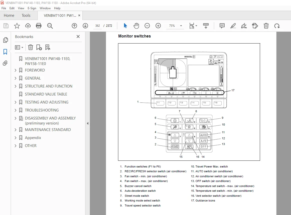
Monitor switches 362
Declaration of switch function on keypad 363
Guidance icon and function switch 365
Operator mode function 368
Service mode function of machine monitor 370
KOMTRAX system 372
Gateway Controller 373
Function of Gateway Controller 373
Communication Terminal 377
KomVision system 378
Layout drawing of KomVision system 378
Chassis part 378
Around cab and floor 379
KomVision system diagram 379
Function of KomVision system 380
KomVision controller 381
Structure of KomVision controller 381
Structure of KomVision camera 385
Overload warning device 386
Outline 386
Function 386
Structure 386
Sensors 387
Ambient pressure sensor 389
Charge (boost) pressure and temperature sensor 390
Coolant temperature sensor 391
Ne (crankshaft) speed sensor 391
Bkup (camshaft) speed sensor 392
Common rail pressure sensor 392
Exhaust manifold pressure sensor 393
Mass air flow and temperature sensor 394
KDPF differential pressure and outlet pressure sensor 395
KDOC inlet temperature sensor 396
KDOC outlet temperature sensor 396
Engine oil level sensor 397
Fuel level sensor 398
WIF (Water-In-Fuel detection) sensor 399
Coolant level sensor 400
Hydraulic oil temperature sensor 401
Air cleaner clogging sensor 401
Overload Caution sensor 402
Swing proximity sensor 403
Brake sensors 403
Brake accumulator low pressure sensor (CN-P60) 404
Brake stop light sensor (CN-S19) 404
Service brake pressure sensor (CN-S40) 404
Service brake pressure sensor (CN-P62) 404
Park brake pressure sensor (CN-P61) 405
PPC pressure sensors and switches 405
Main valve sensor 406
Block pressure sensors and switches 406
DPF-SCR Area 407
PPC levers 408
LH PPC lever 408
RH PPC lever 409
1st attachment circuit hydraulic performance (main valve bypassed) 410
Travel system 411
Travel circuit 411
Travel Motor Performance 412
Auto-grease pump 414
Overview 415
Display and control unit 415
LED-display 416
Push buttons 416
Three-digit LED display 417
Check central lubrication system, fill up grease 418
Lubrication diagrams 419
Auto-grease pump with one-piece boom 419
Auto-grease pump with two-piece boom 420
Manual system one-piece boom 421
Manual system two-piece boom 422
Standard value table for engine related parts 424
Standard value table for chassis related parts 432
Flow control characteristic of PC valve (STD) 444
PM clinic service 445
Check sheet 446
STANDARD VALUE TABLE 423
TESTING AND ADJUSTING 453
Abbreviation list 456
List of abbreviations used in the text 456
List of abbreviations used in the circuit diagrams 460
Engine and cooling system 461
Test engine speed 461
Method for testing engine speed 461
Test boost pressure 464
Method for testing boost pressure on machine monitor 464
Method for testing boost pressure 465
Test exhaust gas colour 466
Method for testing exhaust gas colour by handy smoke checker 466
Method for testing exhaust gas colour by smoke meter 467
Test and adjust valve clearance 469
Method for testing valve clearance 469
Method for adjusting valve clearance 471
Test compression pressure 471
Method for testing compression pressure 472
Test blow by pressure 477
Method for testing blow by pressure 477
Test engine oil pressure 479
Handling fuel system parts 480
Releasing residual pressure from fuel system 481
Test fuel pressure 481
Method for testing fuel pressure 483
Testing of low-pressure circuit (fuel main filter inlet side) 483
Testing of low-pressure circuit (pressure difference) 484
Testing of return circuit 485
Testing of negative pressure circuit 486
Test fuel discharge, return and leakage 487
Tools for testing fuel discharge, return and leakage 487
Method for testing fuel discharge, return and leakage 489
Testing supply pump discharge volume 489
Testing supply pump return rate 490
Testing of leakage from pressure limiter 491
Testing the fuel return rate from injector 492
Bleeding air from fuel system 493
Method for bleeding air from fuel system 493
Test fuel circuit for leakage 494
Method for testing fuel circuit for leakage 494
Testing method of fuel circuit for leakage at engine low idle 495
Testing method of fuel circuit for leakage at engine high idle 495
Testing method of fuel circuit for leakage at engine rated speed 496
Handle cylinder cut-out mode operation 497
Handle no-injection cranking operation 497
Test and adjust air conditioner compressor belt tension 498
Method for checking air conditioner compressor belt 498
Method for adjusting air conditioner compressor belt 498
Replacing the fan belt 500
Test cooling fan speed 501
Method for testing cooling fan speed 501
Write ash in soot accumulation correction to engine controller 502
Method for writing ash in soot accumulation correction to engine controller 502
Test SCR related functions 503
Test AdBlue/DEF pump raised pressure 506
Method for testing AdBlue/DEF pump raised pressure 507
Test injection amount from AdBlue/DEF injector 510
Tools for testing of injection amount from AdBlue/ DEF injector 510
Method for testing injection amount from AdBlue/DEF injector 511
Test AdBlue/DEF line heater relay 1 515
Tools for testing AdBlue/DEF line heater relay 1 515
Method for testing AdBlue/DEF line heater relay 1 516
Test AdBlue/DEF line heater relay 2 518
Tools for testing AdBlue/DEF line heater relay 2 518
Method for testing AdBlue/DEF line heater relay 2 519
Test AdBlue/DEF pump heater relay 521
Tools for testing AdBlue/DEF pump heater relay 521
Method for testing AdBlue/ DEF pump heater relay 522
Test AdBlue/DEF tank heater valve 524
Tools for testing AdBlue/DEF tank heater valve 524
Method for testing AdBlue/DEF tank heater valve 525
Test denitration efficiency of SCR 527
Method for testing denitration efficiency of SCR 528
Clean AdBlue/DEF tank 531
Testing tools for cleaning of AdBlue/DEF tank 531
Method for cleaning AdBlue/DEF tank 531
Bleed air from coolant circuit of AdBlue/ DEF tank 535
Method for bleeding air from coolant circuit of AdBlue/DEF tank 535
Measurement of clearance in swing circle bearing 537
Inspection and adjustment of hydraulic oil pressure in hydraulic circuit for work equipment, swing and travel 538
Measurement 538
Adjustment 539
Inspection and adjustment of control circuit oil pressure 542
Measurement 542
Procedure for pressure reducing adjustment 543
Inspection and adjustment of pump PC (valve inlet) control oil pressure 544
Measurement 544
Adjustment 546
Inspection and adjustment of pump LS differential pressure 548
Measurement 548
Adjustment 551
Measurement of solenoid valve output pressure 552
Checking Proportional Control PPC Circuit 554
Adjustment of work equipment and swing PPC valve 555
Measuring and adjusting quick coupler control valve output pressure 556
Specification 557
Testing travel motor relief pressure 558
Measuring travel motor relief pressure 558
Testing propshaft speed 559
Measuring rotating speed of propshaft 559
Testing transmission clutch control circuit 560
Description 560
Inspection of locations of hydraulic drift of work equipment 562
Release of remaining pressure in hydraulic circuit 564
Measurement of oil leakage 565
Air bleeding of various parts 568
Inspection procedures for diode 571
Electrical system 573
Set and operate machine monitor 573
Specification 574
Operator mode 577
Service mode 582
Table of self-define monitoring 599
Abnormality record menu 607
Default menu 621
Diagnostic tests menu 636
Adjustment menu 648
KOMTRAX settings menu 656
Method for starting up KOMTRAX terminal 660
Inspection and adjustment of ECSS (ACCU pressure) 666
Maintenance 666
Inspection and adjustment of Tool control 671
Troubleshooting 677
Changing the lubrication interval times 681
Changing the Joystick steering control 682
Inspection and adjustment digging brake system 683
Adjust rearview camera angle 685
Method for adjusting rear view camera angle 685
Adjust KomVision camera angle 688
Tools for adjusting KomVision camera angle 688
Method for adjusting KomVision camera angle 689
Angle adjustment method for front R H camera, rear R H camera, and rear L H camera 689
Angle adjustment method for rear camera 691
Adjust KomVision related items 693
Setting of KomVision (main setting) 693
Method for setting KomVision (main setting) 693
Setting of KomVision (camera setting) 696
Method for setting KomVision (camera setting) 696
Setting of KomVision (camera calibration) 696
Method for setting of KomVision (camera calibration) 697
TROUBLESHOOTING 711
Abbreviation list 712
List of abbreviations used in the text 712
List of abbreviations used in the circuit diagrams 716
Related information on troubleshooting 717
General troubleshooting points 717
When the failure code cannot be cleared by “Loaded Diagnostics Operation To Confirm Failure Correction” or “Loaded Diagnostics Operation To Clear Failure Code” 720
Sequence of events in troubleshooting 730
Walk-around check 734
Method for disconnecting and connecting connector with special lock 736
Connector table 747
T-Branch box and T-Branch adapter table 790
T-boxes and T-adapters table 795
Fuse location table 799
Precautions for replacing KDOC 801
Preparation of short circuit electrical connector (for failure codes [CA1883] and [CA3135]) 802
Failure code table (Display of code) 803
Troubleshooting when failure code is indicated 817
Troubleshooting by failure code (Display of code) 827
Failure code [2G00MA] – Brake oil pressure abnormality 827
Failure code [602ENX] – Return filter clogging 828
Failure code [6AZ0MA] – Quick coupler system defective function 829
Failure code [6AZ0ZG] – Quick coupler pressure low 830
Failure code [6B2JMA] – Travel hydraulic abnormality 832
Failure code [879AKA] – A/C recirculation air temperature sensor open circuit 833
Failure code [879AKB] – A/C inner sensor short circuit 834
Failure code [879BKA] – A/C outer sensor open circuit 836
Failure code [879BKB] – A/C outer sensor short circuit 838
Failure code [879CKA] – Ventilating sensor open circuit 840
Failure code [879CKB] – Ventilating sensor short circuit 841
Failure code [879DKZ] – Sunlight sensor open or short circuit 842
Failure code [879EMC] – Ventilation damper abnormality 844
Failure code [879FMC] – Air mix damper abnormality 845
Failure code [879GKX] – Refrigerant abnormality 846
Failure code [989L00] – Engine controller lock caution 1 848
Failure code [989M00] – Engine controller lock caution 2 849
Failure code [989N00] – Engine controller lock caution 3 850
Failure code [A1U0N3] – HC desorb request 1 851
Failure code [A1U0N4] – HC desorb request 2 852
Failure code [A900FR] – Abrupt engine stop by auto idling stop 3 853
Failure code [A900N6] – Abrupt engine stop by auto idling stop 1 854
Failure code [A900NY] – Abrupt engine stop by auto idling stop 2 855
Failure code [AA10NX] – Air cleaner clogging 856
Failure code [AB00KE] – Charge voltage low 858
Failure code [AQ10MB] – Manual stationary regeneration request 2 860
Failure code [AQ10N3] – Manual stationary regeneration request 861
Failure code [AS00R2] – Warning 2 862
Failure code [AS00R3] – Inducement 1 863
Failure code [AS00R4] – Inducement 2 864
Failure code [AS00R5] – Inducement 3 865
Failure code [AS00R6] – Temporary recovery of inducement 866
Failure code [AS00ZK] – AdBlue/DEF level low error 5 867
Failure code [AS10KM] – AdBlue/DEF Injector overheat warning 868
Failure code [AS10NR] – AdBlue/DEF injector high temperature warning 869
Failure code [AS10NT] – AdBlue/DEF injector overheat caution 870
Failure code [B@BAZG] – Engine oil pressure low 871
Failure code [B@BAZK] – Engine oil level low 872
Failure code [B@BCNS] – Engine coolant overheat 873
Failure code [B@BCQA] – Engine coolant level low 874
Failure code [B@BCZK] – Engine coolant level low 876
Failure code [B@HANS] – Hydraulic oil overheat 878
Failure code [CA115] – Engine neutral and backup speed sensor error 880
Failure code [CA122] – Charge air press sensor high error 882
Failure code [CA123] – Charge air press sensor low error 884
Failure code [CA131] – Throttle sensor high error 886
Failure code [CA132] – Throttle sensor low error 888
Failure code [CA144] – Coolant temperature sensor high error 890
Failure code [CA145] – Coolant temperature sensor low error 892
Failure code [CA153] – Charge air temperature sensor high error 894
Failure code [CA154] – Charge air temperature sensor low error 896
Failure code [CA187] – Sensor 2 supply voltage low error 898
Failure code [CA227] – Sensor 2 supply voltage high error 900
Failure code [CA234] – Engine overspeed 902
Failure code [CA238] – NE speed sensor supply voltage error 903
Failure code [CA239] – NE speed sensor supply voltage high error 904
Failure code [CA249] – Ambient air temp sensor high error 906
Failure code [CA256] – Ambient air temp sensor low error 908
Failure code [CA271] – PCV 1 short circuit error 910
Failure code [CA272] – PCV 1 open circuit error 912
Failure code [CA322] – Injector #1 (L#1) open circuit error or short circuit error 914
Failure code [CA324] – Injector #3 (L#3) open circuit error or short circuit error 916
Failure code [CA331] – Injector #2 (L#2) open circuit error or short circuit error 918
Failure code [CA332] – Injector #4 (L#4) open circuit error or short circuit error 920
Failure code [CA343] – Engine controller internal failure 922
Failure code [CA351] – Injectors drive circuit error 922
Failure code [CA352] – sensor 1 supply voltage low error 924
Failure code [CA386] – sensor 1 supply voltage high error 926
Failure code [CA428] – Water in fuel sensor high error 928
Failure code [CA429] – Water in fuel sensor low error 930
Failure code [CA435] – Engine oil pressure SW error 932
Failure code [CA441] – Battery voltage low error 934
Failure code [CA442] – Battery voltage high error 936
Failure code [CA451] – Common rail pressure sensor high error 938
Failure code [CA452] – Common rail pressure sensor low error 940
Failure code [CA488] – Charge air temperature high torque derate 941
Failure code [CA515] – Charge air temperature high torque derate 942
Failure code [CA516] – Common rail pressure sensor supply voltage low error 944
Failure code [CA553] – Common rail pressure high error 1 945
Failure code [CA555] – Crankcase pressure high error 1 946
Failure code [CA556] – Crankcase pressure high error 3 947
Failure code [CA559] – Common rail pressure low error 1 948
Failure code [CA689] – Engine NE speed sensor error 950
Failure code [CA691] – Intake air temperature sensor high error 952
Failure code [CA692] – Intake air temperature sensor low error 954
Failure code [CA697] – Engine controller internal temperature sensor high error 956
Failure code [CA698] – Engine controller internal temperature sensor low error 957
Failure code [CA731] – Engine backup speed sensor phase error 958
Failure code [CA741] – compressor inlet press sensor high error 960
Failure code [CA742] – compressor inlet press sensor low error 962
Failure code [CA743] – compressor inlet press sensor in range error 964
Failure code [CA778] – Engine backup speed sensor error 965
Failure code [CA1117] – Engine controller partial data lost error 970
Failure code [CA1664] – KDOC abnormality 972
Failure code [CA1669] – AdBlue/DEF level sensor voltage high error 974
Failure code [CA1673] – AdBlue/DEF level low error 3 975
Failure code [CA1677] – AdBlue/DEF temperature sensor low error 976
Failure code [CA1678] – AdBlue/DEF temperature sensor high error 977
Failure code [CA1682] – AdBlue/DEF pump priming error 978
Failure code [CA1683] – AdBlue/DEF tank heating valve voltage high error 980
Failure code [CA1684] – AdBlue/DEF tank heating valve voltage low error 982
Failure code [CA1686] – AdBlue/DEF quality sensor voltage high error 984
Failure code [CA1695] – Sensor 5 supply voltage high error 985
Failure code [CA1696] – Sensor 5 supply voltage low error 986
Failure code [CA1712] – AdBlue/DEF tank thawing error 988
Failure code [CA1713] – AdBlue/DEF tank heater valve open stuck error 990
Failure code [CA1714] – AdBlue/DEF quality sensor out of calibration error 992
Failure code [CA1715] – AdBlue/DEF quality sensor internal circuit error 993
Failure code [CA1776] – Sensor supply relay voltage high error 994
Failure code [CA1777] – Sensor supply relay voltage low error 996
Failure code [CA1843] – Crankcase pressure sensor high error 998
Failure code [CA1844] – Crankcase pressure sensor low error 1000
Failure code [CA1879] – KDPF differential pressure sensor high error 1002
Failure code [CA1881] – KDPF differential pressure sensor low error 1004
Failure code [CA1883] – KDPF differential pressure sensor in range error 1006
Failure code [CA1885] – Turbo outlet NOx sensor circuit error 1010
Failure code [CA1887] – SCR outlet NOx sensor circuit error 1012
Failure code [CA1921] – KDPF soot load high error 1 1014
Failure code [CA1922] – KDPF soot load high error 2 1016
Failure code [CA1942] – Crankcase pressure sensor in range error 1019
Failure code [CA1993] – KDPF differential pressure low error 1020
Failure code [CA2185] – Throttle sensor supply voltage high error 1022
Failure code [CA2186] – Throttle sensor supply voltage low error 1024
Failure code [CA2311] – IMV solenoid error 1025
Failure code [CA2373] – Exhaust manifold pressure sensor high error 1026
Failure code [CA2374] – Exhaust manifold pressure sensor low error 1028
Failure code [CA2554] – Exhaust manifold pressure sensor in range error 1030
Failure code [CA2555] – Intake air heater relay open circuit error 1032
Failure code [CA2556] – Intake air heater relay short circuit error 1034
Failure code [CA2637] – KDOC face plugging 1036
Failure code [CA2639] – Manual stationary regeneration request 1038
Failure code [CA2771] – SCR outlet NOx sensor datalink timeout error 1040
Failure code [CA2973] – Charge air pressure sensor in range error 1043
Failure code [CA2976] – AdBlue/DEF pump temperature sensor signal error 1044
Failure code [CA3133] – KDPF outlet pressure sensor high error 1046
Failure code [CA3134] – KDPF outlet pressure sensor low error 1048
Failure code [CA3135] – KDPF outlet pressure sensor in range error 1050
Failure code [CA3142] – SCR temperature sensor high error 1054
Failure code [CA3143] – SCR temperature sensor low error 1055
Failure code [CA3144] – SCR temperature sensor in rage error 1056
Failure code [CA3146] – SCR outlet temperature sensor high error 1058
Failure code [CA3147] – SCR outlet temperature sensor low error 1059
Failure code [CA3148] – SCR outlet temperature sensor in range error 1060
Failure code [CA3151] – SCR catalyst efficiency low error 2 1062
Failure code [CA3165] – SCR outlet temperature high error 1068
Failure code [CA3228] – Turbo outlet NOx sensor in range error 1070
Failure code [CA3229] – SCR temperature high error 1072
Failure code [CA3231] – SCR temperature high error non regeneration 1074
Failure code [CA3232] – Turbo outlet NOx sensor datalink timeout error 1076
Failure code [CA3235] – SCR outlet temperature high error – non regeneration 1080
Failure code [CA3239] – AdBlue/DEF line heater 2 voltage high error 1082
Failure code [CA3241] – AdBlue/DEF line heater 2 voltage low error 1084
Failure code [CA3242] – AdBlue/DEF tank heating error 1086
Failure code [CA3251] – KDOC inlet temperature high error 1088
Failure code [CA3253] – KDOC temperature error – non regeneration 1090
Failure code [CA3254] – KDOC outlet temperature high error 1 1092
Failure code [CA3255] – KDPF temperature error – non regeneration 1094
Failure code [CA3256] – KDPF outlet temperature high error 1 1096
Failure code [CA3311] – KDOC outlet temperature high error 2 1098
Failure code [CA3312] – KDPF outlet temperature high error 2 1100
Failure code [CA3313] – KDOC inlet temperature sensor low error 1102
Failure code [CA3314] – KDOC inlet temperature sensor high error 1103
Failure code [CA3315] – KDOC inlet temperature sensor in range error 1104
Failure code [CA3316] – KDOC outlet temperature sensor low error 1106
Failure code [CA3317] – KDOC outlet temperature sensor high error 1107
Failure code [CA3318] – KDOC outlet temperature sensor in range error 1108
Failure code [CA3319] – KDPF outlet temp sensor high error 1110
Failure code [CA3321] – KDPF outlet temperature sensor low error 1111
Failure code [CA3322] – KDPF outlet temperature sensor in range error 1112
Failure code [CA3497] – AdBlue/DEF level low error 1 1114
Failure code [CA3498] – AdBlue/DEF level low error 2 1115
Failure code [CA3545] – SCR outlet NOx sensor unstable error 1116
Failure code [CA3547] – AdBlue/DEF level low error 4 1118
Failure code [CA3558] – AdBlue/DEF pump voltage high error 1120
Failure code [CA3559] – AdBlue/DEF pump voltage low error 1122
Failure code [CA3562] – AdBlue/DEF LineHeater relay 1 voltage high error 1124
Failure code [CA3563] – AdBlue/DEF LineHeater relay 1 voltage low error 1126
Failure code [CA3567] – AdBlue/DEF injector open circuit error or short circuit error 1128
Failure code [CA3568] – AdBlue/DEF malfunction 1131
Failure code [CA3571] – AdBlue/DEF pump pressure sensor high error 1136
Failure code [CA3572] – AdBlue/DEF pump pressure sensor low error 1138
Failure code [CA3574] – AdBlue/DEF pump pressure too low error 1140
Failure code [CA3575] – AdBlue/DEF pump pressure too high error 1142
Failure code [CA3577] – AdBlue/DEF FCV voltage high error 1144
Failure code [CA3578] – AdBlue/DEF FCV voltage low error 1146
Failure code [CA3583] – SCR outlet NOx sensor heater warming up error 1148
Failure code [CA3596] – AdBlue/DEF pump pressure unstable error 1150
Failure code [CA3649] – Turbo outlet NOx sensor heater warming up error 1154
Failure code [CA3681] – SCR outlet NOx sensor power voltage error 1156
Failure code [CA3682] – Turbo outlet NOx sensor power voltage error 1161
Failure code [CA3713] – AdBlue/DEF line heater 1 voltage high error 1166
Failure code [CA3717] – SCR outlet NOx sensor voltage mismatch error 1168
Failure code [CA3718] – Turbo outlet NOx sensor voltage mismatch error 1169
Failure code [CA3725] – Turbo outlet NOx sensor unstable error 1170
Failure code [CA3741] – Rail press valve trip error 1172
Failure code [CA3748] – Turbo outlet NOx sensor stuck in range error 1174
Failure code [CA3755] – AdBlue/DEF dosing performance degradation error 1176
Failure code [CA3866] – AdBlue/DEF low concentration error 2 1178
Failure code [CA3867] – AdBlue/DEF low concentration error 1 1182
Failure code [CA3868] – AdBlue/DEF tank sensor datalink timeout error 1184
Failure code [CA4151] – KDOC and KDPF temperature sensor datalink timeout error 1187
Failure code [CA4152] – SCR temperature sensor datalink timeout error 1190
Failure code [CA4155] – AdBlue/DEF pump heater relay voltage high error 1194
Failure code [CA4156] – AdBlue/DEF pump heater relay voltage low error 1196
Failure code [CA4157] – AdBlue/DEF FCV malfunction 1198
Failure code [CA4158] – KDOC and KDPF temperature sensor internal circuit error 1200
Failure code [CA4159] – SCR temperature sensor internal circuit error 1201
Failure code [CA4161] – KDOC and KDPF temperature sensor ECU voltage high error 1202
Failure code [CA4162] – KDOC and KDPF temperature sensor ECU voltage low error 1204
Failure code [CA4163] – KDOC and KDPF temperature sensor ECU over temperature error 1206
Failure code [CA4164] – SCR temperature sensor ECU voltage high error 1208
Failure code [CA4165] – SCR temperature sensor ECU voltage low error 1210
Failure code [CA4166] – SCR temperature sensor ECU high temperature error 1212
Failure code [CA4168] – AdBlue/DEF pump heater ON stuck error 1214
Failure code [CA4169] – AdBlue/DEF pump heater OFF stuck error 1216
Failure code [CA4171] – AdBlue/DEF pump thawing error 1218
Failure code [CA4249] – AdBlue/DEF pump temperature sensor 1 in range error 1220
Failure code [CA4251] – AdBlue/DEF pump temperature sensor 2 in range error 1222
Failure code [CA4259] – KDOC and KDPF temperature sensor power interrupt error 1224
Failure code [CA4261] – SCR temperature sensor power interrupt error 1226
Failure code [CA4277] – AdBlue/DEF quality sensor liquid distinction impossible error 1230
Failure code [CA4459] – AdBlue/DEF LineHeater relay 2 voltage high error 1232
Failure code [CA4461] – AdBlue/DEF LineHeater relay 2 voltage low error 1234
Failure code [CA4731] – AdBlue/DEF temperature sensor transmission data error 1236
Failure code [CA4732] – AdBlue/DEF level sensor transmission data error 1237
Failure code [CA4739] – AdBlue/DEF level sensor internal circuit error 1238
Failure code [CA4768] – Fuel in AdBlue/DEF tank error 1240
Failure code [CA4769] – AdBlue/DEF level measurement impossible 1242
Failure code [CA4842] – AdBlue/DEF high concentration error 1244
Failure code [CA4952] – System operating lamp short circuit (engine controller) 1246
Failure code [CA5115] – AdBlue/DEF line heater 1 voltage low error 1248
Failure code [CA5179] – Engine room temperature sensor high error 1252
Failure code [CA5181] – Engine room temperature sensor low error 1254
Failure code [CA5271] – Exhaust throttle valve motor driver voltage high error 1256
Failure code [CA5272] – Exhaust throttle valve motor driver voltage low error 1258
Failure code [CA5273] – Exhaust throttle valve motor driver open error 1260
Failure code [CA5274] – Exhaust throttle valve position sensor in range error 1262
Failure code [CA5275] – Exhaust throttle valve position sensor high error 1264
Failure code [CA5276] – Exhaust throttle valve position sensor low error 1266
Failure code [CA5383] – Ash accumulation high error 1268
Failure code [CA5631] – Manual stationary regeneration request (automatic regeneration uncompleted) 1269
Failure code [CA5632] – Manual stationary regeneration request but regeneration disable 1270
Failure code [CA5655] – SCR catalyst degradation error 1271
Failure code [CA5689] – SCR outlet NOx sensor tamparing error 1276
Failure code [CA5715] – KDPF delta P sensor in range dither error 1278
Failure code [CA5716] – KDPF outlet press sensor in range dither error 1282
Failure code [CA5838] – SCR outlet NOx sensor selfdiag stuck in-range error 1286
Failure code [CA5864] – AdBlue/DEF pump short to battery 1288
Failure code [CA5865] – AdBlue/DEF pump short to ground 1290
Failure code [CA6513] – AdBlue/DEF pump thawing error 1292
Failure code [D110KB] – Battery relay output short circuit 1294
Failure code [D19JKZ] – Personal code relay abnormality 1296
Failure code [D19QKB] – Short circuit in refuel pump relay 1298
Failure code [D19QKY] – Hot short circuit in refuel pump relay 1300
Failure code [D1EMKA] – Parking brake relay open circuit 1302
Failure code [D1EMKB] – Parking brake relay short circuit 1304
Failure code [D1EMKY] – Parking brake relay hot short circuit 1306
Failure code [D811MC] – KOMTRAX malfunction 1308
Failure code [D862KA] – GPS antenna open circuit 1309
Failure code [D8ALKA] – System operating lamp open circuit (KOMTRAX) 1310
Failure code [D8ALKB] – System operating lamp short circuit (KOMTRAX) 1312
Failure code [D8AQKR] – CAN2 discon (KOMTRAX) 1314
Failure code [D8G1KT] – Malfunction (Gateway Controller) 1318
Failure code [D8G6KT] – Malfunction (communication terminal) 1318
Failure code [DA20MC] – Pump controller malfunction 1319
Failure code [DA22KK] – Pump solenoid power low error 1320
Failure code [DA25KP] – 5 V Sensor 1 power voltage low error 1322
Failure code [DA26KP] – 5 V Sensor 2 power voltage low error 1324
Failure code [DA27KP] – 24V sensor power abnormality 1326
Failure code [DA29KQ] – Model selection signal mismatch 1328
Failure code [DA2LKA] – System operating lamp open circuit (pump controller system) 1330
Failure code [DA2LKB] – System operating lamp short circuit 1332
Failure code [DA2QKR] – Controller area network 2 defective communication 1334
Failure code [DA2RKR] – Controller area network 1 defective communication 1338
Failure code [DA80KB] – Auto grease system monitoring signal short circuit 1342
Failure code [DAB0KT] – Internal flash memory error (pump controller system) 1344
Failure code [DAC3KB] – Cruise control system power supply short circuit 1346
Failure code [DAC3KY] – Cruise control system power supply hot short circuit 1348
Failure code [DAF0KM] – Inconsistency of KomVision setting 1350
Failure code [DAF0MB] – Monitor ROM abnormality 1350
Failure code [DAF0MC] – Monitor malfunction 1351
Failure code [DAF8KB] – Camera power supply short circuit 1352
Failure code [DAF9KQ] – Model selection abnormality 1354
Failure code [DAFGMC] – GPS module malfunction 1355
Failure code [DAFLKA] – System operating lamp open circuit (monitor) 1356
Failure code [DAFLKB] – System operating lamp short circuit (monitor) 1358
Failure code [DAFQKR] – CAN 2 defective communication (monitor) 1360
Failure code [DAZ9KQ] – Model selection signal mismatch (Air conditioner) 1364
Failure code [DAZQKR] – CAN 2 defective communication (A/C ECU) 1365
Failure code [DB2QKR] – CAN2 discon (engine con) 1368
Failure code [DB2RKR] – CAN1 discon (engine con) 1373
Failure code [DB30KR] – Joystick steering controller malfunction 1378
Failure code [DBP0KM] – KomVision setting error 1379
Failure code [DBP0KT] – KomVision controller abnormality 1379
Failure code [DBP5KB] – Camera power supply short circuit 1380
Failure code [DBP5KY] – Camera power hot short circuit 1382
Failure code [DBPQKR] – CAN 2 defective communication (KomVision) 1384
Failure code [DCS0KT] – Internal flash memory error (Machine controller system) 1388
Failure code [DCS0MC] – Machine controller malfunction 1389
Failure code [DCS2KK] – Machine controller solenoid power voltage low error 1390
Failure code [DCS5KP] – 5V sensor 1 power voltage low error 1392
Failure code [DCS7KP] – 24V sensor power voltage low error 1394
Failure code [DCS9KQ] – Model selection signal mismatch (machine controller) 1396
Failure code [DCSLKA] – System operating lamp open circuit (machine controller) 1398
Failure code [DCSLKB] – System operating lamp short circuit (machine controller) 1400
Failure code [DCSQKR] – CAN 2 defective communication (machine controller) 1402
Failure code [DCSRKR] – CAN 1 defective communication (machine controller) 1404
Failure code [DDJ1KA] – Quick coupler inductive sensor 1 open circuit 1406
Failure code [DDJ2KA] – Quick coupler inductive sensor 2 open circuit 1408
Failure code [DDK8KA] – SUSLock forced SW open circuit 1410
Failure code [DDK8KB] – SUSLock forced SW short circuit 1412
Failure code [DDKVKA] – Joystick steering activation SW open circuit 1414
Failure code [DDKVKB] – Joystick steering activation SW short circuit 1415
Failure code [DDNRKA] – W/E lever lock SW open circuit 1416
Failure code [DDNRKY] – W/E lever lock SW short circuit 1418
Failure code [DDNS00] – Lock lever auto lock release SW ON 1420
Failure code [DDP4KX] – Disconnection in travel PPC pressure switch 1422
Failure code [DDP6L5] – Service brake press SW abnormality 1424
Failure code [DDQ1KA] – SUSLock mode selection SW open circuit 1426
Failure code [DDQ1KB] – SUSLock mode selection SW short circuit 1428
Failure code [DDWCKZ] – Direction switch abnormality 1430
Failure code [DDWMKZ] – FBR attachment SW abnormality 1432
Failure code [DFB1KZ] – Service lever potentio 1 open or short circuit 1434
Failure code [DFB2KZ] – Service lever potentio 2 open or short circuit 1436
Failure code [DFB3L8] – Service lever 1 potentiometer error 1438
Failure code [DFB4L8] – Service lever 2 potentiometer error 1439
Failure code [DFB6KZ] – Service lever sub potentio 2 open or short circuit 1442
Failure code [DGH2KA] – Hydraulic oil temperature sensor open circuit 1444
Failure code [DGH2KB] – Hydraulic oil temperature sensor ground fault 1446
Failure code [DHA4KA] – Air cleaner clog sensor open circuit 1448
Failure code [DHAAMA] – KDPF differential pressure sensor frozen 1450
Failure code [DHACMA] – KDPF outlet pressure sensor frozen 1451
Failure code [DHH2MA] – Return line filter press sensor abnormally 1452
Failure code [DHPAMA] – Front pump pressure sensor defective function 1454
Failure code [DHS3MA] – Arm IN PPC pressure sensor defective function 1456
Failure code [DHS4MA] – Bucket CURL PPC pressure sensor defective function 1458
Failure code [DHS5KX] – Travel PPC sensor abnormality 1460
Failure code [DHS8MA] – Boom RAISE PPC pressure sensor defective function 1462
Failure code [DHS9MA] – Boom LOWER PPC pressure sensor defective function 1464
Failure code [DHSAMA] – Swing right PPC pressure sensor defective function 1466
Failure code [DHSBMA] – Swing left PPC pressure sensor defective function 1468
Failure code [DHSCMA] – Arm OUT PPC pressure sensor defective function 1470
Failure code [DHSDMA] – Bucket DUMP PPC pressure sensor defective function 1472
Failure code [DHT8KA] – S/T oil pressure sensor open circuit or ground fault 1474
Failure code [DHT8KB] – S/T oil pressure sensor hot short circuit 1476
Failure code [DHT8ZG] – S/T oil pressure low 1478
Failure code [DHU1KA] – Brake accumulator press sensor open circuit 1480
Failure code [DHU1KY] – Brake accumulator press sensor short circuit 1482
Failure code [DHUCKA] – Parking brake press sensor open circuit 1484
Failure code [DHUCKY] – Parking brake press sensor short circuit 1486
Failure code [DHUGKA] – Service brake press sensor open circuit 1488
Failure code [DHUGKY] – Service brake press sensor short circuit 1490
Failure code [DHX1MA] – Overload sensor abnormality 1492
Failure code [DKULKA] – PPC lock relay open circuit 1494
Failure code [DKULKB] – PPC lock relay short circuit 1496
Failure code [DKULKY] – PPC lock relay hot short circuit 1498
Failure code [DLM5KA] – Fan speed sensor open circuit 1500
Failure code [DLM5MB] – Fan control: mismatch 1502
Failure code [DLT4KA] – Speed sensor open circuit 1504
Failure code [DLT4KB] – Speed sensor short circuit 1506
Failure code [DR10KA] – KomVision camera open circuit 1508
Failure code [DR12KA] – Disconnection of camera 1 NTSC input 1510
Failure code [DR20KA] – Disconnection of camera 2 NTSC input 1512
Failure code [DR30KA] – Disconnection of camera 3 NTSC input 1514
Failure code [DR31KX] – Camera 3 picture reverse drive input out of range 1516
Failure code [DR40KA] – Disconnection of camera 4 NTSC input 1518
Failure code [DUMBKA] – Operating lamp open circuit (KomVision) 1520
Failure code [DUMBKB] – Operating lamp short circuit (KomVision) 1522
Failure code [DV00KA] – Buzzer output open circuit (KomVision) 1524
Failure code [DV00KB] – Buzzer output short circuit (KomVision) 1525
Failure code [DV20KB] – Travel alarm short circuit 1526
Failure code [DW44KA] – Travel F/R solenoid open circuit 1528
Failure code [DW44KB] – Travel F/R solenoid short circuit 1530
Failure code [DW44KY] – Travel F/R solenoid hot short circuit 1532
Failure code [DW45KA] – Swing parking brake solenoid open circuit 1534
Failure code [DW45KB] – Swing parking brake solenoid short circuit 1536
Failure code [DW45KY] – Swing parking brake solenoid hot short circuit 1538
Failure code [DW4AKA] – Disconnection in suspension lock solenoid 1540
Failure code [DW4AKB] – Short circuit in suspension lock solenoid 1542
Failure code [DW4AKY] – SUSLock sol hot short circuit 1544
Failure code [DW4CKY] – PPC lock solenoid hot short circuit 1546
Failure code [DW4MKA] – Disconnection in creep solenoid 1548
Failure code [DW4MKB] – Short circuit in creep solenoid 1549
Failure code [DW4MKY] – Hot short circuit in creep solenoid 1550
Failure code [DW4YKA] – Disconnection in high gear solenoid 1552
Failure code [DW4YKB] – Short circuit in high gear solenoid 1554
Failure code [DW4YKY] – High gear hot short circuit 1556
Failure code [DW4ZKA] – Disconnection in low gear solenoid 1558
Failure code [DW4ZKB] – Short circuit in low gear solenoid 1560
Failure code [DW4ZKY] – Low gear hot short circuit 1562
Failure code [DW91KA] – Travel neutral sol open circuit 1564
Failure code [DW91KB] – Travel neutral sol short circuit 1566
Failure code [DW91KY] – Travel neutral sol hot short circuit 1568
Failure code [DWA2KA] – Attachment single or 2-way change solenoid open circuit (breaker mode relay) 1570
Failure code [DWA2KB] – Attachment single or 2-way change solenoid short circuit (breaker mode relay) 1572
Failure code [DWA2KY] – Attachment single or 2-way change solenoid hot short circuit (breaker mode relay) 1574
Failure code [DWB1KA] – Outrigger selection sol relay open circuit 1576
Failure code [DWB1KB] – Outrigger selection sol relay short circuit 1578
Failure code [DWB2KA] – Disconnection in 1st outrigger solenoid 1580
Failure code [DWB2KB] – Outrigger sol 1 short circuit 1582
Failure code [DWB2KY] – Outrigger sol 1 hot short circuit 1584
Failure code [DWB3KA] – Outrigger sol 2 open circuit 1586
Failure code [DWB3KB] – Outrigger sol 2 short circuit 1588
Failure code [DWB3KY] – Outrigger sol 2 hot short circuit 1590
Failure code [DWB4KA] – Outrigger sol 3 open circuit 1592
Failure code [DWB4KB] – Outrigger sol 3 short circuit 1594
Failure code [DWB4KY] – Outrigger sol 3 hot short circuit 1596
Failure code [DWB5KA] – Outrigger sol 4 open circuit 1598
Failure code [DWB5KB] – Outrigger sol 4 short circuit 1600
Failure code [DWB5KY] – Outrigger sol 4 hot short circuit 1602
Failure code [DWK0KA] – 2-stage relief solenoid open circuit 1604
Failure code [DWK0KB] – 2-stage relief solenoid short circuit 1606
Failure code [DWK0KY] – 2-stage relief solenoid hot short circuit 1608
Failure code [DWK2KA] – Variable back pressure solenoid open circuit 1610
Failure code [DWK2KB] – Variable back pressure solenoid short circuit 1612
Failure code [DWK2KY] – Variable back pressure solenoid hot short circuit 1614
Failure code [DWKSKA] – Boom float sol open circuit 1616
Failure code [DWKSKB] – Boom float sol short circuit 1618
Failure code [DWKSKY] – Boom float sol hot short circuit 1620
Failure code [DWMAKA] – Two piece boom suspension sol open circuit 1622
Failure code [DWMAKB] – Two piece boom suspension sol short circuit 1624
Failure code [DWMAKY] – Two piece boom suspension sol hot short circuit 1626
Failure code [DWMBKA] – Work equipment PPC reduction solenoid open circuit 1628
Failure code [DWMBKB] – Work equipment PPC reduction solenoid short circuit 1630
Failure code [DWMBKY] – Work equipment PPC reduction solenoid hot short circuit 1632
Failure code [DWMCKA] – Auxiliary hydraulic circuit 1 solenoid open circuit 1634
Failure code [DWMCKB] – Auxiliary hydraulic circuit 1 solenoid short circuit 1635
Failure code [DWMCKY] – Auxiliary hydraulic circuit 1 solenoid hot short circuit 1636
Failure code [DWMDKB] – Auxiliary hydraulic circuit 2 solenoid short circuit 1638
Failure code [DWMDKY] – Auxiliary hydraulic circuit 2 solenoid hot short circuit 1640
Failure code [DWN5KA] – Fan clutch solenoid open circuit 1642
Failure code [DWN5KB] – Fan clutch solenoid short circuit 1644
Failure code [DWN5KY] – Fan clutch solenoid hot short circuit 1646
Failure code [DXA8KA] – Pump PC-EPC solenoid open circuit 1648
Failure code [DXA8KB] – Pump PC-EPC solenoid short circuit 1650
Failure code [DXE0KA] – LS-EPC solenoid open circuit 1652
Failure code [DXE0KB] – LS-EPC solenoid short circuit 1654
Failure code [DXE7KA] – Attachment flow regulating EPC 2 solenoid open circuit 1656
Failure code [DXE7KB] – Attachment flow regulating EPC 2 solenoid short circuit 1658
Failure code [DXE7KY] – Attachment flow regulating EPC 2 solenoid hot short circuit 1660
Failure code [DXE8KA] – Attachment flow regulating EPC 3 solenoid open circuit 1662
Failure code [DXE8KB] – Attachment flow regulating EPC 3 solenoid short circuit 1664
Failure code [DXE8KY] – Attachment flow regulating EPC 3 solenoid hot short circuit 1666
Failure code [DXE9KA] – Attachment flow regulating EPC 4 solenoid open circuit 1668
Failure code [DXE9KB] – Attachment flow regulating EPC 4 solenoid short circuit 1670
Failure code [DXE9KY] – Attachment flow regulating EPC 4 solenoid hot short circuit 1672
Failure code [DXEAKA] – Attachment flow regulating EPC 5 solenoid open circuit 1674
Failure code [DXEAKB] – Attachment flow regulating EPC 5 solenoid short circuit 1676
Failure code [DXEAKY] – Attachment flow regulating EPC 5 solenoid hot short circuit 1678
Failure code [DXEKKA] – Attachment variable press EPC1 open circuit 1680
Failure code [DXEKKB] – Attachment variable press EPC1 short circuit 1682
Failure code [DXEKKY] – Attachment variable press EPC1 hot short circuit 1684
Failure code [DXELKA] – Attachment variable press EPC2 open circuit 1686
Failure code [DXELKB] – Attachment variable press EPC2 short circuit 1688
Failure code [DXELKY] – Attachment variable press EPC2 hot short circuit 1690
Failure code [DXK3KA] – Travel pedal throttle EPC solenoid open circuit 1692
Failure code [DXK3KB] – Travel pedal throttle EPC solenoid short circuit 1693
Failure code [DY20KA] – Wiper motor open circuit 1694
Failure code [DY20MA] – Wiper motor defective function 1696
Failure code [DY2CKB] – Washer motor short circuit 1698
Failure code [DY2DKB] – Wiper motor (normal rotation) short circuit 1700
Failure code [DY2EKB] – Wiper motor (reverse rotation) short circuit 1702
Failure code [F311KA] – Centralized warning lamp signal 1 open circuit 1704
Failure code [F311KB] – Centralized warning lamp signal 1 short circuit 1706
Failure code [F312KA] – Centralized warning lamp signal 2 open circuit 1708
Failure code [F312KB] – Centralized warning lamp signal 2 short circuit 1710
Failure code [F313KA] – Communication terminal startup signal open circuit 1712
Failure code [F313KB] – Communication terminal startup signal short circuit 1714
Failure code [F314KA] – Software update signal open circuit 1716
Failure code [F314KB] – Software update signal short circuit 1718
Failure code [F315KA] – Engine controller WAKE signal open circuit 1720
Failure code [F315KB] – Engine controller WAKE signal short circuit 1722
Failure code [F316KA] – 3rd party component startup signal open circuit 1724
Failure code [F316KB] – 3rd party component startup signal short circuit 1726
Failure code [F318KB] – Communication terminal power supply 1 short circuit 1728
Failure code [F318KY] – Communication terminal power supply 1 hot short circuit 1730
Failure code [F31AKB] – Ethernet power supply short circuit 1732
Failure code [F31AKY] – Ethernet power supply hot short circuit 1734
Failure code [F31BKB] – 5V sensor power supply short circuit (Gateway controller) 1736
Failure code [F31BKY] – 5V sensor power supply hot short circuit (Gateway controller) 1738
Failure code [F31CKB] – 12V sensor power supply short circuit (Gateway controller) 1740
Failure code [F31CKY] – 12V sensor power supply hot short circuit (Gateway controller) 1742
Failure code [F31DKB] – 24V sensor power supply short circuit (Gateway controller) 1744
Failure code [F31DKY] – 24V sensor power supply hot short circuit (Gateway controller) 1746
Failure code [F31EKB] – 24V sensor power supply booster output short circuit (Gateway controller) 1748
Failure code [F31EKY] – 24V sensor power supply booster output hot short circuit (Gateway controller) 1750
Failure code [F7FQKR] – CAN2 discon (ID Key Con) 1752
Failure code [F7G0MC] – ID key receiving antenna malfunction 1756
Troubleshooting of central lubrication system (CLS) 1757
Trouble 1757
Troubleshooting during grease pump operation 1759
Pump element 1760
Check power supply 1761
Changing the control unit 1761
Troubleshooting – grease system faults 1762
Venting of the system 1763
General assembly advice 1764
Troubleshooting of engine (S-mode) 1765
S-1 Engine does not crank when starting switch is turned to start position 1766
S-2 Engine cranks but no exhaust gas comes out 1767
S-3 Fuel is being injected but engine does not start (misfiring: engine cranks but does not start) 1768
S-4 Engine startability is poor 1769
S-5 Engine does not pick up smoothly 1771
S-6 Engine stops during operation 1774
S-7 Engine runs rough or is unstable 1775
S-8 Engine lacks power 1776
S-9 Exhaust smoke is black 1778
S-10 Engine oil consumption is excessive 1779
S-11 Oil becomes contaminated quickly 1780
S-12 Fuel consumption is excessive 1781
S-13 Oil is in coolant (or coolant spurts back or coolant level goes down) 1782
S-14 Oil pressure drops 1783
S-15 Fuel mixes into engine oil 1784
S-16 Water mixes into engine oil (milky) 1785
S-17 Coolant temperature rises too high (overheating) 1786
S-18 Unusual noise is heard 1787
S-19 Vibration is excessive 1788
S-20 Air cannot be bled from fuel circuit 1789
S-21 Active regeneration is executed frequently 1790
S-22 Active regeneration takes time 1791
S-23 White smoke is exhausted during active regeneration 1792
S-24 AdBlue/DEF consumption is excessive 1793
S-25 There is unusual smell (irritating odor) 1794
S-26 Foreign materials enter AdBlue/DEF (AdBlue/DEF increases) 1795
DISASSEMBLY AND ASSEMBLY (preliminary version) 1797
FRONT AXLE 1797
Note 1798
Table of contents 1799
Preface 1801
General 1802
Examples of gear-tooth contact pattern for the Gleason gear-tooth system 1804
Conversion table 1808
Denomination of standard dimensions 0
Tightening torques for screws 1810
Special tools 1811
Commercial tools 1823
1 Disassembly steering 1828
2 Disassembly output 1831
2 1 Disassembly planetary carrier 1831
2 2 Disassembly brake 1832
2 3 Disassembly hub 1834
2 4 Disassembly knuckle housing 1835
2 5 Disassembly output assy 1837
3 Disassembly input 1838
4 Disassembly differential 1842
4 1 DZ-500 and D-500 1842
4 2 DZ-750 and D-750 1845
5 Reassembly differential 1847
5 1 DZ-500 and D-500 1847
5 2 DZ-750 and D-750 1851
6 Reassembly input 1855
6 1 Install input pinion 1855
6 1 1 Determine thickness of the shim to obtain a correct contact pattern 1855
6 1 2 Setting of rolling torque of the input pinion bearing 1857
6 2 Setting instructions for bevel gear set backlash and bearing rolling torque of the differential bearing 1859
6 2 1 Check of backlash pattern of the bevel gear set 1861
6 3 Mount shaft seal ring (input flange) 1863
7 Reassembly output 1864
7 1 Preassembly axle housing 1864
7 2 Reassembly knuckle housing 1865
7 3 Reassembly hub 1869
7 4 Reassembly disk brake 1871
7 4 1 Make leakage test of multi-disk brake 1874
7 4 2 Adjust and check piston stroke 1875
7 5 Reassembly planetary carrier 1877
7 6 Reassembly output assy 1878
7 7 Reassembly pivot bearing 1879
8 Reassembly steering 1880
8 1 Preassemble steering 1880
8 2 Mount steering 1883
8 3 Track setting and checking 1885
8 4 Steering angle setting 1886
8 5 Check leakage of steering 1887
REAR AXLE 1888
Note 1889
Table of contents 1890
Preface 1892
General 1893
Examples of gear-tooth contact pattern for the Gleason gear-tooth system 1895
Conversion table 1899
Denomination of standard dimensions 1900
Tightening torques for screws 1901
Special tools 1902
Commercial tools 1909
1 Disassembly of output 1914
1 1 Disassembly of planetary carrier 1914
1 2 Disassembly of brake 1915
1 3 Disassembly of hub 1917
1 4 Disassembly of output assy 1919
2 Disassembly of input 1920
2 1 Version with HL transmission 1920
2 2 Standard version 1922
3 Disassembly differential 1925
3 1 DZ-500 und D-500 1925
3 2 DZ-750 und D-750 1928
4 Reassembly differential 1930
4 1 DZ-500 und D-500 1930
4 2 DZ-750 und D-750 1934
5 Reassembly of input 1938
5 1 Version with HL-transmission 1938
5 1 1 Determination of shims for setting the bearing rolling torque (differential bearing) and the backlash (bevel gear set) 1938
5 2 Standard version (without HL transmission) 1943
5 2 1 Reinstallation of input pinion 1943
5 2 2 Adjust backlash of crown wheel set and bearing rolling torque of differential bearing 1946
5 2 3 Fitting of shaft seal ring (input flange) 1950
6 Reassembly of output 1951
6 1 Reassembly of hub carrier 1951
6 2 Reassembly of hub (Hub bearing SET-RIGHT) 1951
6 3 Reassembly of multi-disk brake 1954
6 3 1 Leakage test of multi-disk brake 1957
6 3 2 Adjustment and check of piston stroke 1958
6 4 Reassembly of planetary carrier 1959
6 5 Reassembly of output assy 1960
TRANSMISSION 1961
Note 1962
Table of contents 1963
Preface 1965
General 1966
Conversion table 1968
Denomination of standard dimensions 1969
Torque limits for screws 1970
Special tools 1971
Commercial tools 1980
1 Separate HL-Transmission from axle housing 1985
2 Disassembly – Brake/Clutch/Planetary carrier 1986
2 1 Lubrication pump and shift interlock 1986
2 1 1 Version “Lubrication pump” 1986
2 2 Speed sensor 1987
2 3 Emergency release (Parking Brake) 1987
2 4 Input housing and modulation valve 1988
2 5 Brake and clutch 1989
2 6 Planetary carrier 1995
3 Disassembly – Output 1998
3 1 Version “Axle attachment” 1998
3 2 Version “Separate Installation” 2002
4 Reassembly – Output 2005
4 1 Version “Axle attachment” 2005
4 1 1 Determine shim for pinion gap 2007
4 1 2 Determine adjusting ring for rolling torque/pinion bearing 2011
4 1 3 Check rolling torque of pinion bearing 2012
4 1 4 Shaft seal output flange 2013
4 1 5 Check the pinion gap 2014
4 2 Version “Separate installation” 2015
4 2 1 Shaft seal output flange 2018
5 Reassembly – Brake/Clutch/Planety carrier 2021
5 1 Planetary carrier 2021
5 2 Brake and clutch 2025
5 2 1 Disc components brake and clutch 2027
5 2 1 1 Version “HL-290” 2027
5 2 1 2 Version “HL-270” 0
5 2 1 3 Version “HL-250” 2027
5 2 2 Adjust and check the disc clearance/piston stroke of brake and clutch 2029
5 3 Install modulation valve and input housing 2036
5 4 Emergency release (Parking brake) 2038
5 4 1 Check emergency release for leak tightness 2039
5 4 2 Check the multi-disk brake and multi-disc clutch for leak tightness as well as closing pressure 2040
5 5 Speed sensor 2041
5 6 Lubrication pump/shift interlock 2041
6 Disassembly – Lubrication pump/shift interlock and valve block 2043
6 1 Version “with” lubrication pump 2043
6 2 Version “with” hydr shift interlock 2046
6 3 Disassembly valve block 2049
7 Reassembly Lubrication pump 2051
8 Reassembly shift interlock 2057
9 Valve block (shifting low gear – high gear) 2065
10 Mount HL-Transmission to axle 2066
MAINTENANCE STANDARD 2067
Abbreviation list 2068
List of abbreviations used in the text 2068
Engine and cooling system 2072
Maintenance standard of engine mount 2072
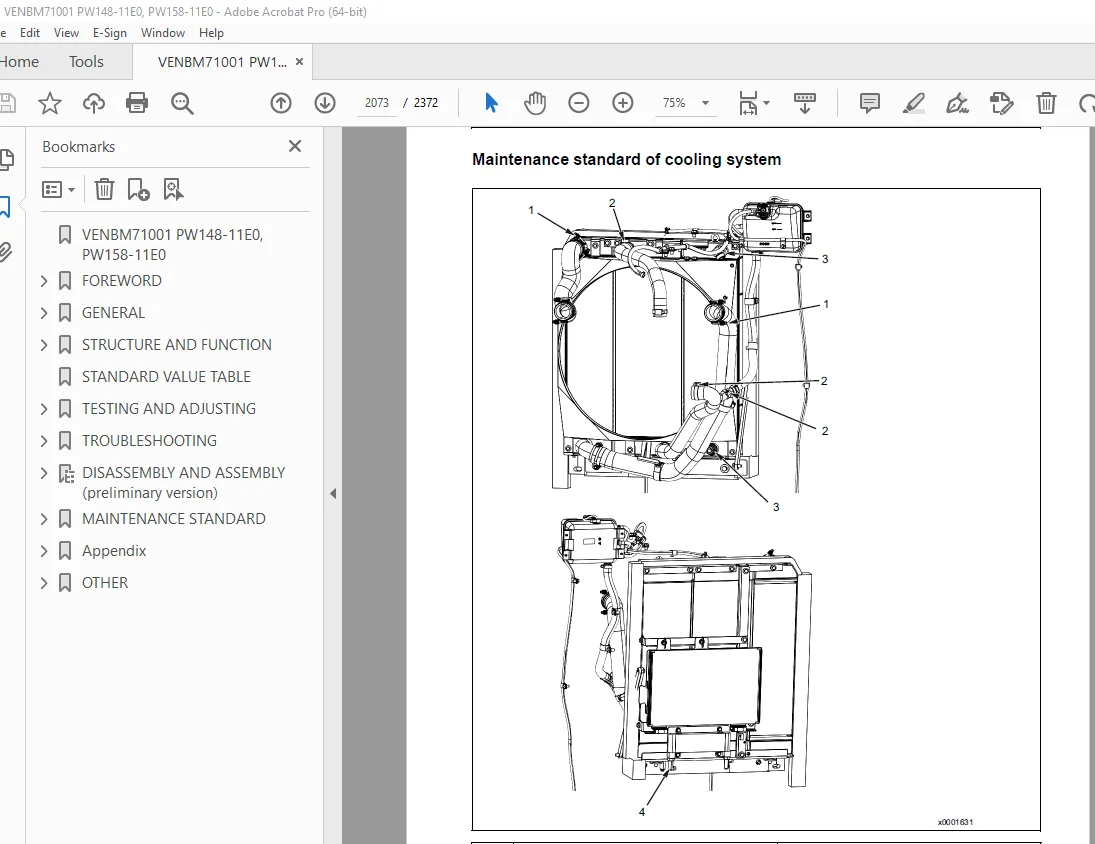
Maintenance standard of cooling system 2073
Power train 2075
Maintenance standard of swing circle 2075
Maintenance standard of swing machinery 2076
Axles 2077
Gear box 2078
Prop shaft 2080
Orbitrol valve (STD/JSS) 2081
Trailer preparation 2082
Cabin mounting 2084
Hydraulic system 2087
Maintenance standard of hydraulic tank 2087
Main pump 2088
Maintenance standard of LS-EPC valve 2091
Maintenance standard of PC-EPC valve 2092
Control valve 2093
Maintenance standard of anti-drop valve for 1 boom LH 2094
Maintenance standard of anti-drop valve for 1 boom RH 2096
Maintenance standard of anti-drop valve for 2 boom 2098
Maintenance standard of anti-drop valve for arm/bucket 2100
Maintenance standard of work equipment and swing PPC valve 2102
Solenoid valve block 2108
Swivel joint 2109
Work equipment 2110
Work equipment linkage 2110
1 Dimension of arm 2112
2 Dimension of bucket 2114
Hydraulic cylinder 2115
Boom cylinder 2115
Arm cylinder 2115
Bucket cylinder 2115
Adjust cylinder 2116
Appendix 2119
Abbreviation list 2122
List of abbreviations used in the text 2122
List of abbreviations used in the circuit diagrams 2126
Air conditioner system 2127
Precautions for refrigerant 2127
Air conditioner component 2128
Specifications of air conditioner 2130
Outline of refrigeration cycle 2132
Component parts of air conditioner system 2134
Air conditioner unit 2134
Configuration diagram of air conditioner unit 2134
Component parts of air conditioner unit 2138
Function of evaporator as air conditioner unit component 2139
Function of heater core as air conditioner unit component 2139
Function of evaporator temperature sensor as air conditioner unit component 2139
Function of servo motor as air conditioner unit component 2139
Structure of expansion valve as air conditioner unit component 2140
Air conditioner controller 2142
Structure of air conditioner controller 2142
Compressor 2143
Structure of compressor 2143
Specifications of compressor 2143
Function of compressor 2143
Condenser 2144
Structure of condenser 2144
Specifications of condenser 2144
Function of condenser 2144
Sensors for air conditioner system 2146
Structure of sunlight sensor 2146
Function of sunlight sensor 2146
Structure of ambient temperature sensor 2146
Function of ambient temperature sensor 2147
Explanation of procedure for testing and troubleshooting of air conditioner 2148
Circuit diagram and arrangement of connector pins for air conditioner 2150
Air conditioner system diagram 2152
Input and output signals of air conditioner controller 2153
Function of air conditioner controller 2154
Installation locations of air conditioner parts and arrangement of connectors 2155
Fuses layout in the fuse boxes 2156
Air conditioner controller and connectors layout 2156
Air conditioner unit and connectors layout 2157
Sunlight sensor connectors layout 2157
Machine monitor connectors layout 2157
Dual pressure switch connectors layout 2157
Air conditioner compressor connectors layout 2158
Outside air temperature sensor connectors layout 2158
Testing air leakage (DUCT) 2159
Method for testing air leakage (DUCT) 2159
Testing air conditioner using self-diagnosis function 2161
How to open the electrical system abnormality record screen in service mode of the machine monitor 2162
Test vent (mode) changeover 2163
Testing FRESH/RECIRC air changeover 2165
Method for testing FRESH/RECIRC air changeover 2165
Test sunlight sensor 2166
Method for testing sunlight sensor 2166
Test (dual) pressure switch for refrigerant 2167
Method for testing (dual) pressure switch for refrigerant 2167
Test relays 2168
Method for testing relays 2168
Air conditioner troubleshooting chart 1 2169
Air conditioner troubleshooting chart 2 2170
Information described in troubleshooting table 2173
Failure code [879AKA] A/C recirculation air temperature sensor open circuit 2174
Failure code [879AKB] A/C recirculation air temperature sensor short circuit 2175
Failure code [879BKA] A/C fresh air temperature sensor open circuit 2176
Failure code [879BKB] A/C fresh air temperature sensor short circuit 2178
Failure code [879CKA] Ventilating sensor open circuit 2180
Failure code [879CKB] Ventilating sensor short circuit 2181
Failure code [879DKZ] Sunlight sensor open circuit or short circuit 2182
Failure code [879EMC] Ventilation damper malfunction 2184
Failure code [879FMC] Air mix damper malfunction 2185
Failure code [879GKX] Refrigerant pressure input signal out of range 2186
A-1 Troubleshooting for power supply system (air conditioner does not operate) 2188
A-2 Troubleshooting for compressor and refrigerant system (air is not cooled) 2191
A-3 Troubleshooting for blower motor system (no air comes out or air flow is abnormal) 2194
A-4 Troubleshooting for FRESH/RECIRC air changeover 2196
Troubleshooting using gauge pressure 2198
Connection of service tool 2200
Method for connecting service tool 2201
Precautions for disconnection 2202
Precautions for connection 2203
Handle compressor oil 2204
Management of compressor oil (DENSO: ND-OIL8 for R134a) 2204
The quantity of compressor oil when the compressor is replaced 2204
Method for replacing desiccant 2206
Joystick Steering 2208
Overview of failure groups and descriptions 2208
Error handling 2210
1 Malfunction of Pump controller 2210
1 1 Joystick activation signals have the same value 2210
2 Malfunction of SASA-sensor 2210
2 1 CRC 2210
2 2 CAN Count 2210
2 3 CAN Timeout 2210
2 4 Sensor chip 2210
2 5 Steering angle 2210
2 6 CAN Input Message 2210
2 7 Power 2210
2 8 CPU 2210
2 9 Memory 2210
2 10 Temperature 2210
2 11 Angle Not Available (from CAN) 2210
2 12 RPM Not Available (from CAN) 2210
2 13 CAN Redundant 2210
2 14 Sensor 2210
2 15 RAM Corruption 2210
3 Malfunction of Hall-sensor 2211
3 1 Joystick signals out of range 2211
3 2 Joystick redundant signals mismatch 2211
3 3 Joystick out of neutral when activating steering system 2211
3 4 No signal available 2211
4 Malfunction of PVES (electrical activation) Orbitrol 2211
4 1 Steering valve feedback value out of range (beneath 25% UDC or above 75% UDC) 2211
4 2 Steering valve feedback (SP) value and control value (US) mismatch 2211
4 3 Error pin (C2p01) high signal, also indicated on PVES-SP LED: 2212
5 Wiring-failure 2212
5 1 Joystick signals out of range 2212
5 2 Joystick redundant signals mismatch 2212
5 3 Joystick Mode signals have the same value 2212
5 4 Cut Off valve current output and feedback mismatch 2212
5 5 Steering valve supply current output and feedback mismatch 2212
5 6 Steering valve control duty output and feedback mismatch 2212
5 7 Steering valve control 2212
5 8 Steering valve supply 2212
5 9 Steering valve failure signal 2212
5 10 Cut Off valve outputs 2212
5 11 Joystick mode switch reference 2212
5 12 Failure LED output 2212
5 13 Joystick mode inputs 2213
5 14 Joystick active inputs 2213
5 15 Joystick signals 2213
5 16 Steering valve failure signal input 2213
5 17 Steering valve position feedback input 2213
6 Miscellaneous 2213
6 1 CAN time out 2213
6 2 Joystick calibration failure 2213
6 3 SASA Sensor CAN Timeout 2213
6 4 CAN bus failure 2213
6 5 Bus Off 2213
6 6 Driver Error 2213
6 7 Passive Mode Error 2213
6 8 Overflow 2213
6 9 Joystick Mode signals have the same value 2213
6 10 Joystick steering profile parameters out of range 2213
7 Failure of SC024-120 2213
7 1 HWPCBVoltages InRange 2213
7 2 OS CrcStatus 2213
7 3 OS ChecksumFailure 2213
7 4 SafetyLayer Failure 2213
7 5 Battery power outside of allowable ranges 2213
7 6 Sensor power outside of specified ranges 2213
7 7 NVMem Status 2214
8 Error descriptions 2216
8 1 Inputs 1 2216
8 2 Inputs 2 2219
8 3 Safety function 1 2220
8 4 Outputs 1 2221
8 5 Outputs 2 2225
8 6 Joystick controller internal 2227
8 7 Error Counters Page 1 2228
8 8 Error Counters Page 2 2237
9 Acronyms 2242
OTHER 2243
Hydraulic circuit diagram (1/3) 2247
Hydraulic circuit diagram (2/3) 2249
Hydraulic circuit diagram (3/3) 2251
Contents 2253
Contents 2254
1-0 Power Supply 2255
1-1 Grounding 2256
1-2 Model Select 2257
2-0 Engine 2258
2-1 Engine 2259
2-2 Engine power supply, Air intake 2260
2-3 Engine start 2261
2-4 2nd Engine stop, Operating lamp 2262
2-5 ADBlue/DEF datalink 2263
2-6 ADDBlue/DPF power 2264
3-0 Refueling system, Fuel dial 2265
3-1 Brake 2266
3-2 EPC 2267
3-3 Cruise control 2268
3-4 Travel 2269
3-5 SUS-Lock, Speedsnr, Joystick POTI 2270
3-6 Sensors engine & oil 2271
4-0 Quick coupler, Pressure sensor 2272
4-1 PPC reduction, Floating, Pressure sensor 2273
4-2 Swing lock, Pressure sensor, Joystick SW 2274
4-3 Bucket/2ATT switching 2275
5-0 Lower attachments 2276
5-1 Roto-tilt 2277
5-2 Boom/Stabiliser, Auxilary circuit, Breaker 2278
6-0 Road light 2279
6-1 Indicator, Side light, Stop light 2280
6-2 Arm marker light & QC signal boom 2281
6-3 Beacon, Trailer (opt) 2282
6-4 Worklamp 2283
6-5 Worklamp 2284
6-6 Camera SW, Service-con , KOMNET 2285
6-7 GATEWAY controller 2286
6-8 KomVision 2287
7-0 Air condition, Heated mirror 2288
7-1 Radio, 12V socket, Cigar lighter, Room lamp 2289
7-2 PPC-Lock, Starter cut, Seat 2290
7-3 ID-key 2291
7-4 Horn, Travel alarm 2292
7-5 Wiper, Washer 2293
8-0 CLS 2294
9-0 Joystick steering 2295
10-0 Fan clutch, Tool control 2296
11-0 ECSS 2297
12-0 Digging brake 2298
Harness summary 2299
Connector List W2-1 2300
Connector List W2-2 2301
Connector List W2-3 2302
Connector List W2-4 2303
Connector List W2-5 2304
Connector List W2-6 2305
Connector List W2-7 2306
Pin Location List W3-1 2307
Pin Location List W3-2 2308
Pin Location List W3-3 2309
Pin Location List W3-4 2310
Pin Location List W3-5 2311
Pin Location List W3-6 2312
Pin Location List W3-7 2313
Pin Location List W3-8 2314
Pin Location List W3-9 2315
Pin Location List W3-10 2316
Pin Location List W3-11 2317
Pin Location List W3-12 2318
Pin Location List W3-13 2319
Pin Location List W3-14 2320
Pin Location List W3-15 2321
Pin Location List W3-16 2322
Pin Location List W3-17 2323
Pin Location List W3-18 2324
Pin Location List W3-19 2325
Pin Location List W3-20 2326
Pin Location List W3-21 2327
Pin Location List W3-22 2328
Pin Location List W3-23 2329
Pin Location List W3-24 2330
Pin Location List W3-25 2331
Pin Location List W3-26 2332
Pin Location List W3-27 2333
Pin Location List W3-28 2334
Pin Location List W3-29 2335
Pin Location List W3-30 2336
Pin Location List W3-31 2337
Pin Location List W3-32 2338
Pin Location List W3-33 2339
Pin Location List W3-34 2340
Pin Location List W3-35 2341
Pin Location List W3-36 2342
Pin Location List W3-37 2343
Pin Location List W3-38 2344
Pin Location List W3-39 2345
Pin Location List W3-40 2346
Pin Location List W3-41 2347
Pin Location List W3-42 2348
Pin Location List W3-43 2349
Pin Location List W3-44 2350
Pin Location List W3-45 2351
Pin Location List W3-46 2352
Pin Location List W3-47 2353
Parts List W4-1 2354
Parts List W4-2 2355
Parts List W4-3 2356
Parts List W4-4 2357
Parts List W4-5 2358
Connector diagram 1/12 2361
Connector table for revolving frame harness 1 2361
Connector diagram 2/12 2362
Connector table for revolving frame harness 2 2362
Connector diagram 3/12 2363
Connector table for operator‘s cab wiring harness (Part 1/2) 2363
Connector diagram 4/12 2364
Connector table for operators cab wiring harness (Part 2/2) 2364
Connector diagram (5/12) 2365
Connector table switch group 2365
Connector diagram (6/12) 2366
Connector table steering 2366
Connector diagram (7/12) 2367
Connector table various wiring harness 2367
Connector diagram (8/12) 2368
Connector table optionally wiring harness (Part 1/3) 2368
Connector diagram (9/12) 2369
Connector table optionally wiring harness (Part 2/3) 2369
Connector diagram (10/12) 2370
Connector table optionally wiring harness (Part 3/3) 2370
Connector diagram (11/12) 2371
Connector diagram (12/12) 2372
Connector table for Brake valve a , electric 2372
DESCRIPTION:
Komatsu PW148-11E0 PW158-11E0 Wheeled Excavator Shop Manual VENBM71001 – PDF DOWNLOAD
MACHINE MODEL SERIAL NUMBER
PW148-11E0 H56051 AND UP
PW158-11E0 H58551 AND UP
GENERAL PRECAUTIONS :
Mistakes in operation are extremely dangerous. Read the OPERATION & MAINTENANCE MANUAL carefully BEFORE operating the machine.
PREPARATIONS FOR WORK:
PRECAUTIONS DURING WORK :
S.V 31/12/24


