
Komatsu SAA6D107E-1-A SAA6D107E-1-B Engine Shop Manual SEN06615-02 PDF
$28.95
Komatsu SAA6D107E-1-A SAA6D107E-1-B Engine Shop Manual SEN06615-02 – PDF DOWNLOAD
Description
Komatsu SAA6D107E-1-A SAA6D107E-1-B Engine Shop Manual SEN06615-02 – PDF DOWNLOAD
FILE DETAILS:
Komatsu SAA6D107E-1-A SAA6D107E-1-B Engine Shop Manual SEN06615-02 – PDF DOWNLOAD
Language : English
Pages : 364
Downloadable : Yes
File Type : PDF
TABLE OF CONTENTS:
Komatsu SAA6D107E-1-A SAA6D107E-1-B Engine Shop Manual SEN06615-02 – PDF DOWNLOAD
Cover 1
00 Index and foreword 3
Table of contents 4
Safety notice 7
How to read the shop manual 12
Explanation of terms for maintenance standard 14
Handling of electric equipment and hydraulic component 16
Handling of connectors newly used for engines 25
How to read electric wire code 28
Precautions when carrying out operation 31
Method of disassembling and connecting push-pull type coupler 34
Standard tightening torque table 37
Conversion table 41
01 Specification 47
General 48
Specifications 49
General view 52
Engine performance curve 57
10 Structure, function and maintenance standard 61
Air intake and exhaust units 64
Intake system 66
Exhaust system 67
Turbocharger 70
Lubricating oil system 73
Cooling system 77
Fuel system 78
Main moving parts 82
Cylinder head 86
Cylinder block 91
Crankshaft 94
Piston, piston ring and piston pin 96
Connecting rod 97
Vibration damper 98
Timing gear 99
Front cover 101
Camshaft 102
Valve system 104
Valve and valve guide 108
Rocker arm, shaft and tappet 110
Oil pump 112
Oil pan 114
Flywheel and flywheel housing 115
Oil filter 120
Oil cooler 121
Regulator valve and safety valve 122
Cylinder block 123
Fuel system diagram 124
Fuel supply pump 125
Fuel filter 128
Water pump drive and fan drive 129
Water pump 130
Alternator 131
Starting motor 133
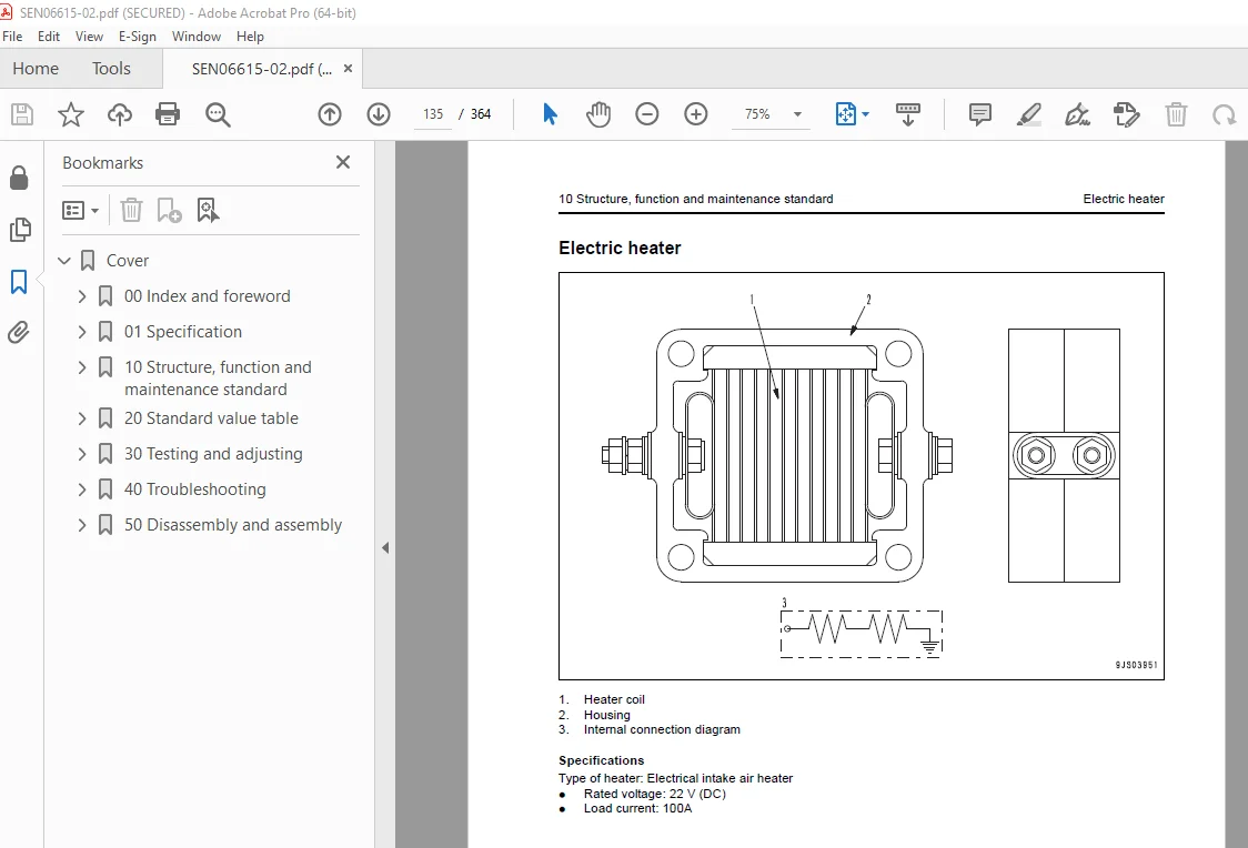
Electric heater 135
20 Standard value table 137
Standard value table for testing, adjusting and troubleshooting 138
Run-in standard and performance test criteria 140
30 Testing and adjusting 143
Precautions Before Work 144
Testing and adjusting tools list 145
Testing air boost pressure 147
Adjustment of valve clearance 148
Testing compression pressure 150
Testing blow-by pressure 153
Testing engine oil pressure 154
Handling fuel system parts 155
Releasing residual pressure in fuel system 155
Testing fuel pressure 156
Reduced cylinder mode operation 158
No-injection cranking 158
Testing leakage from pressure limiter and return rate from injector 159
Bleeding air from fuel circuit 163
Testing fuel system for leakage 164
Replacing the fan belt 165
Handling controller high-voltage circuit 165
Functions of troubleshooting tool and check of failure code 167
40 Troubleshooting 173
Precautions Before Work 175
General information on troubleshooting 176
Failure code table 177
Information in troubleshooting table 179
Method of using troubleshooting charts 181
Troubleshooting for mechanical system (S mode) 184
S-1 Starting performance is poor 184
S-2 Engine does not start 185
S-3 Engine does not pick up smoothly 188
S-4 Engine stops during operations 189
S-5 Engine does not rotate smoothly 190
S-6 Engine lacks output (or lacks power) 191
S-7 Exhaust smoke is black (incomplete combustion) 192
S-8 Oil consumption is excessive (or exhaust smoke is blue) 193
S-9 Oil becomes contaminated quickly 194
S-10 Fuel consumption is excessive 195
S-11 Oil is in coolant (or coolant spurts back or coolant level goes down) 196
S-12 Oil pressure drops 197
S-13 Oil level rises (Entry of coolant or fuel) 198
S-14 Coolant temperature becomes too high (overheating) 199
S-15 Abnormal noise is made 200
S-16 Vibration is excessive 201
Troubleshooting for electrical system (E mode) 202
E-1 Failure code [111] Abnormality in engine controller 202
E-2 Failure code [115] Engine Ne or Bkup speed sensor error 203
E-3 Failure code [122] Abnormally high level in charge pressure sensor 204
E-4 Failure code [123] Abnormally low level in charge pressure sensor 206
E-5 Failure code [131] Throttle sensor high error 208
E-6 Failure code [132] Throttle sensor low error 210
E-7 Failure code [143] (Torque derating by low engine oil pressure) 212
E-8 Failure code [144] Abnormally high level in coolant temperature sensor 214
E-9 Failure code [145] Abnormally low level in coolant temperature sensor 216
E-10 Failure code [146] (Engine overheating) 218
E-11 Failure code [153] Abnormally high level in charge temperature sensor 220
E-12 Failure code [154] Abnormally low level in charge temperature sensor 222
E-13 Failure code [187] Abnormally low level in sensor power supply 2 224
E-14 Failure code [221] Abnormally high level in atmospheric pressure sensor 226
E-15 Failure code [222] Abnormally low level in atmospheric pressure sensor 228
E-16 Failure code [227] Abnormally high level in sensor power supply 2 230
E-17 Failure code [234] Engine overspeed 231
E-18 Failure code [238] Abnormally level in Ne speed sensor power supply 232
E-19 Failure code [271] Short circuit in IMV 233
E-20 Failure code [272] Disconnection in IMV 234
E-21 Failure code [322] Disconnection, short circuit in injector No 1 (L/B No 1) 236
E-22 Failure code [323] Disconnection, short circuit in injector No 5 (L/B No 5) 238
E-23 Failure code [324] Disconnection, short circuit in injector No 3 (L/B No 3) 240
E-24 Failure code [325] Disconnection, short circuit in injector No 6 (L/B No 6) 242
E-25 Failure code [331] Disconnection, short circuit in injector No 2 (L/B No 2) 244
E-26 Failure code [332] Disconnection, short circuit in injector No 4 (L/B No 4) 246
E-27 Failure code [342] Matching error in engine controller data 248
E-28 Failure code [351] Abnormality in injector drive circuit 250
E-29 Failure code [352] Abnormally low level in sensor power supply 1 254
E-30 Failure code [386] Abnormally high level in sensor power supply 1 256
E-31 Failure code [415] (Rotation derating by low engine oil pressure) 257
E-32 Failure code [418] Water mixed in fuel 258
E-33 Failure code [428] Abnormally high level in water sensor 260
E-34 Failure code [429] Abnormally low level in water sensor 262
E-35 Failure code [431] Idle validation switch error 264
E-36 Failure code [432] Idle validation action error 266
E-37 Failure code [435] Abnormality in engine oil pressure switch 268
E-38 Failure code [441] Abnormally low power supply voltage 270
E-39 Failure code [442] Abnormally high power supply voltage 273
E-40 Failure code [449] Abnormally high common rail pressure 2 276
E-41 Failure code [451] Abnormally high level in common rail pressure sensor 278
E-42 Failure code [452] Abnormally low level in common rail pressure sensor 280
E-43 Failure code [488] Derating of torque by abnormally high charge temperature 282
E-44 Failure code [553] Abnormally high common rail pressure 1 283
E-45 Failure code [559] No-pressure feed by supply pump 1 284
E-46 Failure code [689] Abnormality in engine Ne speed sensor 286
E-47 Failure code [731] Abnormality in engine Bkup speed sensor phase 288
E-48 Failure code [757] Loss of all data in engine controller 290
E-49 Failure code [778] Abnormality in engine Bkup speed sensor 294
E-50 Failure code [2185] Throttle sensor supply voltage high error 299
E-51 Failure code [2186] Throttle sensor power supply low error 300
E-52 Failure code [2249] No-pressure feed by supply pump 2 301
E-53 Failure code [2311] Abnormality in IMV solenoid 303
E-54 Failure code [2555] Disconnection in intake air heater relay 305
E-55 Failure code [2556] Short circuit in intake air heater relay 309
50 Disassembly and assembly 313
Precautions Before Work 314
How to read this manual 315
Coating materials list 317
Special tools list 320
General disassembly of engine 321
General assembly of engine 335
DESCRIPTION:
Komatsu SAA6D107E-1-A SAA6D107E-1-B Engine Shop Manual SEN06615-02 – PDF DOWNLOAD
How to read the shop manual
1. Composition of shop manual
This shop manual contains the necessary technical information for services performed in a workshop.
For ease of understanding, the manual is divided into the following sections.
00. Index and foreword
This section explains the shop manuals list, table of contents, safety, and basic information.
01. Specification
This section explains the specifications of the machine.
10. Structure, function and maintenance standard
This section explains the structure, function, and maintenance standard values of each component.
The structure and function sub-section explains the structure and function of each component. It
serves not only to give an understanding of the structure, but also serves as reference material for
troubleshooting. The maintenance standard sub-section explains the criteria and remedies for disassembly
and service.
20. Standard value table
This section explains the standard values for new machine and judgement criteria for testing,
adjusting, and troubleshooting. This standard value table is used to check the standard values in
testing and adjusting and to judge parts in troubleshooting.
30. Testing and adjusting
This section explains measuring instruments and measuring methods for testing and adjusting, and
method of adjusting each part. The standard values and judgement criteria for testing and adjusting
are explained in Testing and adjusting.
40. Troubleshooting
This section explains how to find out failed parts and how to repair them. The troubleshooting is
divided by failure modes. The “S mode” of the troubleshooting related to the engine may be also
explained in the Chassis volume and Engine volume. In this case, see the Chassis volume.
50. Disassembly and assembly
This section explains the special tools and procedures for removing, installing, disassembling, and
assembling each component, as well as precautions for them. In addition, tightening torque and
quantity and weight of coating material, oil, grease, and coolant necessary for the work are also
explained.
IMAGES PREVIEW OF THE MANUAL:
S.V 25/12/24



