Komatsu SK1020-5N, SK1020-5NA Skid Steer Loader Shop Manual CEBM013902 – PDF DOWNLOAD
Original price was: $69.95.$21.95Current price is: $21.95.
Komatsu SK1020-5N, SK1020-5NA Skid Steer Loader Shop Manual
SERIAL NUMBERS:
SK1020-5N A70001 and up
SK1020-5NA A60001 and up
Description
Komatsu SK1020-5N, SK1020-5NA Skid Steer Loader Shop Manual
FILE DETAILS:
Komatsu SK1020-5N, SK1020-5NA Skid Steer Loader Shop Manual
Brands: Komatsu
Equipment Type: Skid Steer Loader
Manuals Type: Shop Manual
Machine Model: SK1020-5N, SK1020-5NA
Serial Number: A70001 and up, A60001 and up
Book Code: CEBM013902
Language: English
Pages: 370
File Format: Portable Document Format (PDF)
DESCRIPTION:
Komatsu SK1020-5N, SK1020-5NA Skid Steer Loader Shop Manual
GENERAL :
- This shop manual has been prepared as an aid to improve the quality of repairs by giving the serviceman an accurate understanding of the product and by showing him the correct way to perform repairs and make judgements. Make sure you understand the contents of this manual and use it to full effect at every opportunity.
- This shop manual mainly contains the necessary technical information for operations performed in a service workshop. For ease of understanding, the manual is divided into the following sections. These sections are further divided into each main group of components.
GENERAL:
This section lists the general machine dimensions, performance specifications, component weights, and fuel, coolant and lubricant specification charts.
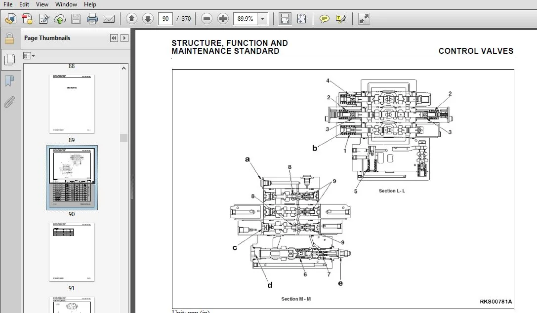
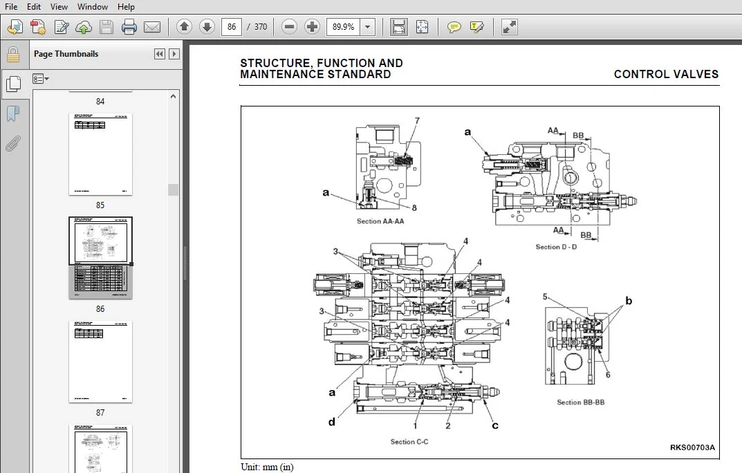
STRUCTURE, FUNCTION AND MAINTENANCE STANDARD:
This section explains the structure and function of each component. It serves not only to give an understanding of the structure, but also serves as reference material for troubleshooting. In addition, this section gives the judgement standards when inspecting disassembled parts.
STANDARD VALUE TABLE:
This section explains the standard values for new machine and judgement criteria for testing, adjusting and troubleshooting. This standard value table is used to check the standard values in testing and adjusting and to judge parts in troubleshooting.
TESTING AND ADJUSTING:
This section explains checks to be made before and after performing repairs, as well as adjustments to be made at completion of the checks and repairs.
TROUBLESHOOTING:
Troubleshooting charts correlating “Problems” to “Causes” are included in this section.
DISASSEMBLY AND ASSEMBLY:
This section explains the order to be followed when removing, installing, disassembling or assembling each component, as well as precautions to be taken for these operations.
DIAGRAMS AND SCHEMATICS
This section has the foldout drawings for the machine.
TABLE OF CONTENTS:
Komatsu SK1020-5N, SK1020-5NA Skid Steer Loader Shop Manual
COVER................................................................................................  1
	CONTENTS.........................................................................................  2
	SAFETY...........................................................................................  9
		SAFETY NOTICE................................................................................  9
		IMPORTANT SAFETY NOTICE......................................................................  9
		GENERAL PRECAUTIONS..........................................................................  0
		PREPARATIONS FOR WORK........................................................................  0
		PRECAUTIONS DURING WORK...................................................................... 10
	GENERAL.......................................................................................... 11
	HOW TO READ THE SHOP MANUAL...................................................................... 12
		Volumes...................................................................................... 12
		Distribution and Updating.................................................................... 12
		Filing Method................................................................................ 12
		Revised Edition Mark......................................................................... 12
		Revisions.................................................................................... 12
		Symbols...................................................................................... 12
	HOISTING INSTRUCTIONS............................................................................ 13
		Hoisting.....................................................................................  0
		Wire Ropes...................................................................................  0
	MAINTENANCE STANDARD TERMINOLOGY................................................................. 14
	HANDLING ELECTRIC EQUIPMENT AND HYDRAULIC COMPONENTS............................................. 16
	PUSH PULL COUPLER................................................................................  0
		Type 1....................................................................................... 25
			Disconnection............................................................................ 25
			Connection............................................................................... 25
		Type 2....................................................................................... 26
			Disconnection............................................................................ 26
			Connection............................................................................... 26
		Type 3....................................................................................... 27
			Disconnection............................................................................ 27
			Connection............................................................................... 27
	COATING MATERIALS................................................................................ 28
	STANDARD TIGHTENING TORQUE....................................................................... 30
		Bolts and Nuts Standard Tightening Torque.................................................... 30
		Hose Nuts Tightening Torque.................................................................. 31
		Split Flange Bolts Tightening Torque......................................................... 31
		Tightening Torque For Flared Nuts............................................................ 31
		O-Ring Boss Piping Joints Tightening Torque.................................................. 32
		O-Ring Boss Plugs Tightening Torque.......................................................... 32
		Hoses (Taper Seal Type And Face Seal Type) Tightening Torque................................. 33
	SPECIFIC DRIVING TORQUE.......................................................................... 33
	ELECTRIC WIRE CODE............................................................................... 34
		Classification by Thickness.................................................................. 34
		Classification by Color and Code............................................................. 34
	CONVERSION TABLES................................................................................ 35
		Method of Using the Conversion Table......................................................... 35
00 FOREWORD..........................................................................................  2
	CONTENTS.........................................................................................  3
	SAFETY...........................................................................................  9
		SAFETY NOTICE................................................................................  9
		IMPORTANT SAFETY NOTICE......................................................................  9
		GENERAL PRECAUTIONS..........................................................................  9
		PREPARATIONS FOR WORK........................................................................  9
		PRECAUTIONS DURING WORK...................................................................... 10
	GENERAL.......................................................................................... 11
	HOW TO READ THE SHOP MANUAL...................................................................... 12
		Volumes...................................................................................... 12
		Distribution and Updating.................................................................... 12
		Filing Method................................................................................ 12
		Revised Edition Mark......................................................................... 12
		Revisions.................................................................................... 12
		Symbols...................................................................................... 12
	HOISTING INSTRUCTIONS............................................................................ 13
		Hoisting..................................................................................... 13
		Wire Ropes................................................................................... 13
	MAINTENANCE STANDARD TERMINOLOGY................................................................. 14
	HANDLING ELECTRIC EQUIPMENT AND HYDRAULIC COMPONENTS............................................. 16
	PUSH PULL COUPLER................................................................................ 25
		Type 1....................................................................................... 25
			Disconnection............................................................................ 25
			Connection............................................................................... 25
		Type 2....................................................................................... 26
			Disconnection............................................................................ 26
			Connection............................................................................... 26
		Type 3.......................................................................................  0
			Disconnection............................................................................ 27
			Connection............................................................................... 27
	COATING MATERIALS................................................................................ 28
	STANDARD TIGHTENING TORQUE....................................................................... 30
		Bolts and Nuts Standard Tightening Torque.................................................... 30
		Hose Nuts Tightening Torque.................................................................. 31
		Split Flange Bolts Tightening Torque......................................................... 31
		Tightening Torque For Flared Nuts............................................................ 31
		Tightening Torque For Flared Nuts............................................................ 32
		O-Ring Boss Piping Joints Tightening Torque.................................................. 32
		O-Ring Boss Plugs Tightening Torque.......................................................... 32
		Hoses (Taper Seal Type And Face Seal Type) Tightening Torque................................. 33
	SPECIFIC DRIVING TORQUE.......................................................................... 33
	ELECTRIC WIRE CODE............................................................................... 34
		Classification by Thickness.................................................................. 34
		Classification by Color and Code............................................................. 34
	CONVERSION TABLES................................................................................ 35
		Method of Using the Conversion Table......................................................... 35
01 GENERAL........................................................................................... 41
	DIMENSION DRAWINGS............................................................................... 42
		Machine Dimensions........................................................................... 42
		Working Ranges............................................................................... 43
	SPECIFICATIONS................................................................................... 44
	WEIGHT TABLE..................................................................................... 46
	FUEL COOLANT AND LUBRICANTS...................................................................... 47
	SERVICE NOTES.................................................................................... 48
10 STRUCTURE, FUNCTION AND MAINTENANCE STANDARD...................................................... 49
	WORK EQUIPMENT PIVOT POINT CLEARANCES............................................................ 51
	WHEEL DRIVE SYSTEM............................................................................... 53
		Power Train Flow............................................................................. 53
		Transmission System.......................................................................... 54
		Wheel Axles.................................................................................. 55
	DRIVE MOTOR SYSTEM............................................................................... 56
		Motor Ports.................................................................................. 56
		Motor Structure.............................................................................. 57
		Motor Operations............................................................................. 58
			Description.............................................................................. 58
	HYDRAULIC PUMPS.................................................................................. 61
		Drive Dampener............................................................................... 61
			Maintenance Standard..................................................................... 61
		Charge Pump.................................................................................. 62
		HST Pump LPV45 + 45 (Standard and High Flow)................................................. 63
			Maintenance Standard..................................................................... 63
		Pump Internal View........................................................................... 65
		Operation of Main Pump....................................................................... 66
		Shuttle Valve................................................................................ 68
	SAFETY VALVES.................................................................................... 69
		Suction Safety Valve Action.................................................................. 69
		Charge Safety Valve Action................................................................... 72
	ANTI ENGINE-STALL VALVE (AS VALVE)............................................................... 74
		AS Valve Maintenance Standard................................................................ 76
	CONTROL VALVES................................................................................... 77
		Standard 3-Spool Valve Port Location......................................................... 77
		Valve-Sectional Views........................................................................ 78
		Super High-Flow 4-Spool Valve Port Location.................................................. 80
		Valve-Sectional Views........................................................................ 81
		Control Valve Maintenence Standard........................................................... 84
			Control Valve (Standard)................................................................. 92
			Control Valve (Super High-Flow).......................................................... 94
	CLOSED CENTER LOAD SENSING SYSTEM................................................................ 96
		Pressure Compensation Control................................................................ 96
		Hydraulic Circuit Diagram.................................................................... 98
		System in Series Circuit Operation........................................................... 99
		Self Leveling Function.......................................................................100
		System in Series-Parallel Circuit Operation..................................................101
		Pressure Compensation Valve..................................................................102
		Dividing Function............................................................................103
	SOLENOID VALVE...................................................................................104
		Valve Group ST1..............................................................................104
	ACCUMULATOR......................................................................................105
	PATTERN CHANGE VALVE.............................................................................106
		Maintenance Standard.........................................................................106
		Pattern Options Arrangement..................................................................108
		Pattern ISO..................................................................................108
		Pattern Optional.............................................................................108
	R.H. PPC VALVE (STANDARD)........................................................................109
		Equipment Control............................................................................109
		R.H. PPC Valve Maintenance Standard..........................................................110
	R.H. PPC VALVE (PATTERN CHANGE)..................................................................112
		Equipment and Travel Control.................................................................112
	L.H. PPC VALVE (STANDARD)........................................................................115
		Travel Control...............................................................................115
		Standard.....................................................................................116
		Maintenance Standard.........................................................................117
	L.H. PPC VALVE (PATTERN CHANGE)..................................................................120
		Equipment and Travel Control.................................................................120
		Pattern Change...............................................................................121
		Maintenance Standard.........................................................................122
	CYLINDERS........................................................................................124
		Boom.........................................................................................124
		Bucket.......................................................................................124
		Maintenance Standard.........................................................................125
20 STANDARD VALUE TABLES.............................................................................  0
	STANDARD SERVICE VALUE TABLE.....................................................................129
	Standard Service Value Table for Engine..........................................................130
	Standard Value Table for Chassis.................................................................131
30 TESTING AND ADJUSTING.............................................................................  0
	SPECIAL TOOLS....................................................................................137
	T-ADAPTER PROCEDURES AND KITS....................................................................138
	ENGINE COMPONENTS................................................................................139
		Measuring Exhaust Smoke......................................................................139
		Measuring Exhaust Temperature................................................................139
		Adjusting Valve Clearance....................................................................139
		Measuring Compression Pressure...............................................................139
		Measuring Crankcase Pressure.................................................................139
		Measuring Engine Oil Pressure................................................................139
		Measuring Boost Pressure.....................................................................139
		Measuring Fuel Pressure......................................................................139
		Adjusting Engine Speed Sensor................................................................139
		Bleeding Air From Fuel System................................................................139
		Adjusting Engine Stop Solenoid...............................................................139
		Adjusting Engine Speed.......................................................................140
	ADJUSTING PPC VALVE PRESSURES....................................................................141
		Adjusting PPC Valve..........................................................................143
	ADJUSTING SERVO-CONTROL SAFETY SENSOR............................................................144
	CHAIN TENSION....................................................................................145
		Test.........................................................................................145
		Adjustment...................................................................................145
	TESTING AND ADJUSTING THE HYDRAULIC SYSTEM.......................................................146
		Relieving Hydraulic Pressure.................................................................147
		Bleeding Hydraulic Circuits..................................................................148
	HYDRAULIC PUMP...................................................................................149
		Calibrating Valve............................................................................150
		Travel Deviation Check.......................................................................151
	CONTROL VALVE....................................................................................154
		Servo-Control Power Supply...................................................................156
	AIR CONDITIONING SYSTEM..........................................................................160
		Environmental Impact.........................................................................160
		Basic Air Conditioning System (Typical)......................................................161
		Operator Cab Air Conditioning................................................................162
		Principles of Refrigeration..................................................................162
		Air Conditioning.............................................................................162
		The Act of Cooling...........................................................................162
		The Refrigeration Cycle......................................................................163
		Air Conditioner System Components............................................................163
			Compressor (Refrigerant Pump)............................................................163
			Service Valves...........................................................................163
			Condenser................................................................................164
			Receiver-Drier...........................................................................164
			Thermostatic Expansion Valve.............................................................164
			Evaporator...............................................................................165
			Electrical Circuit.......................................................................165
			Thermostat...............................................................................166
			Compressor Clutch........................................................................166
			Safety Switches..........................................................................166
			System Servicing.........................................................................167
		R-134A Refrigerant Containers................................................................168
			Service Tools and Equipment..............................................................168
				Recovery/Recycle Station.............................................................168
				Leak Detector........................................................................169
				Service Valves.......................................................................169
				Vacuum Pump..........................................................................169
				Manifold Gauge Set...................................................................170
				Installing Manifold Gauge Set........................................................171
				Purging Air from Service Hoses.......................................................172
				Adding Refrigerant to the System (Without a Charging Station)........................173
				Stabilizing the AC System............................................................173
				Adding Refrigerant and Stabilizing the System (With a Recovery/Recycling Station)....174
				Recovering and Recycling the Refrigerant.............................................174
				Performing the Recovery Cycle........................................................174
				Performing the Recycling Procedure...................................................175
				Evacuating and Charging the AC System................................................175
				System Performance Test..............................................................176
			System Leak Testing......................................................................177
				Electronic Leak Detector.............................................................177
				Tracer Dyes..........................................................................177
				Soap and Water.......................................................................177
			System Repair............................................................................178
				Hoses and Fittings...................................................................178
				Lines................................................................................178
				Expansion Valve......................................................................178
				Receiver-Drier.......................................................................178
				Thermostat...........................................................................178
				Clutch...............................................................................179
				Compressor...........................................................................179
			Checking Compressor Oil Level............................................................179
			Evacuating The System....................................................................180
			Troubleshooting - Air Conditioning System................................................181
				Pre-Diagnosis Checks.................................................................181
				Preparing for Diagnosis..............................................................181
				Preliminary Steps....................................................................181
				System Performance Test..............................................................181
				Diagnosis of Gauge Readings and System Performance...................................182
			Troubleshooting by Manifold Gauge Set Readings...........................................183
			Preventive Maintenance Schedule for A/C System...........................................188
40 TROUBLESHOOTING...................................................................................191
	POINTS TO REMEMBER WHEN TROUBLESHOOTING..........................................................192
	SEQUENCE OF EVENTS IN TROUBLESHOOTING............................................................194
		Points To Remember When Troubleshooting Electrical Circuits..................................195
	CHECKS BEFORE TROUBLESHOOTING....................................................................196
		Troubleshooting Procedure....................................................................197
	CONNECTION TABLE FOR CONNECTOR PIN NUMBERS.......................................................198
	T-ADAPTER TABLE..................................................................................222
	ENGINE COOLANT TEMPERATURE SENSOR FAILURE........................................................225
	ABNORMAL ENGINE OIL PRESSURE INDICATED...........................................................226
	AIR CLEANER CLOG INDICATED.......................................................................227
	ENGINE PREHEAT SYSTEM INOPERABLE.................................................................228
	FUEL LEVEL INDICATION IS INCORRECT...............................................................230
	FUEL PUMP MOTOR INOPERATIVE......................................................................231
	ENGINE DOES NOT SHUT DOWN OR WILL NOT START......................................................232
	ALTERNATOR NOT CHARGING BATTERY..................................................................234
	ENGINE WILL NOT CRANK............................................................................236
	BACK-UP ALARM WILL NOT FUNCTION..................................................................238
	HYDRAULIC FILTER SENSOR WARNING..................................................................240
	PPC SYSTEM ELECTRICAL MALFUNCTION................................................................242
	SEAT SAFETY SWITCH MALFUNCTION...................................................................244
	SAFETY BAR SWITCH MALFUNCTION....................................................................245
	TRAVEL SPEEDS CANNOT BE CHANGED..................................................................246
	FLOAT CONTROL MALFUNCTION........................................................................248
	PARKING BRAKE SYSTEM MALFUNCTION.................................................................250
	PATTERN CHANGE MALFUNCTION.......................................................................252
	STABALIZER SYSTEM MALFUNCTION....................................................................254
	LOW OR WEAK TRAVEL, WEAK BRAKE-OUT FORCE.........................................................258
	WEAK TRAVEL, WEAK BREAK-OUT FORCE IN REVERSE.....................................................260
	ROTATING BEACON INOPERABLE.......................................................................262
	REAR WORK LIGHTS WILL NOT OPERATE................................................................264
	HORN DOES NOT SOUND..............................................................................266
	POSSIBLE DEFECTIVE SAFETY RELAY UNIT.............................................................268
50 DISASSEMBLY AND ASSEMBLY..........................................................................271
	HOW TO READ THIS MANUAL..........................................................................274
		Removal And Installation Of Assemblies.......................................................274
			Special Tools............................................................................274
			Removal..................................................................................274
			Installation.............................................................................274
		Disassembly And Assembly Of Assemblies.......................................................275
			Special Tools............................................................................275
			Disassembly..............................................................................275
			Assembly.................................................................................276
	CONNECTOR REPAIR PROCEDURES......................................................................277
		Stripping Insulation.........................................................................277
		Wire Inspection..............................................................................277
		Contact Terminal Removal (HD30 Type).........................................................278
		Crimping Contact Terminal (HD30 Type)........................................................279
		Insertion Of Contact Terminal (HD30 Type)....................................................280
		Contact Terminal Removal (DT Type)...........................................................281
		Crimping Contact Terminal (DT Type)..........................................................282
		Insertion Of Contact Terminal (DT Type)......................................................283
	ENGINE...........................................................................................284
		Alternator...................................................................................284
		Cylinder Head................................................................................284
		Engine Front Seal............................................................................284
		Engine Oil Cooler............................................................................284
		Engine Rear Seal.............................................................................284
		Fuel Injection Pump..........................................................................284
		Nozzle Holder................................................................................284
		Thermostat...................................................................................284
		Turbocharger.................................................................................284
		Water Pump...................................................................................284
	ENGINE HOOD ASSEMBLY.............................................................................285
		Removal of Engine Hood.......................................................................285
		Installation of Engine Hood..................................................................285
	OPERATOR’S CAB ASSEMBLY..........................................................................286
		Tilting the Cab..............................................................................286
		Lowering the Cab.............................................................................288
		Removing the Cab Assembly....................................................................289
		Installing the Cab...........................................................................291
	WORK EQUIPMENT SYSTEM............................................................................292
		Removing Lift Arms...........................................................................292
		Installation of Lift Arms....................................................................293
	REMOVING EQUIPMENT SUPPORT FRAME.................................................................294
		Installing Support Frame.....................................................................294
	BATTERY..........................................................................................295
		Removal......................................................................................295
		Installation.................................................................................295
	STARTER MOTOR....................................................................................296
		Removal......................................................................................296
		Installation.................................................................................296
	ALTERNATOR.......................................................................................297
		Removal......................................................................................297
		Installation.................................................................................297
		Check and Adjust Fan Belt Tension............................................................297
	AIR FILTER ASSEMBLY..............................................................................298
		Removal......................................................................................298
		Installation.................................................................................298
	MUFFLER ASSEMBLY (SK1020-5N).....................................................................299
		Removal......................................................................................299
		Installation.................................................................................300
	MUFFLER ASSEMBLY (SK1020-5N TURBO)...............................................................301
		Removal......................................................................................301
		Installation.................................................................................302
	RADIATOR ASSEMBLY................................................................................303
		Removal......................................................................................303
		Installation.................................................................................304
	FUEL TANK ASSEMBLY...............................................................................305
		Removal......................................................................................305
		Installation.................................................................................306
	ENGINE-PUMP ASSEMBLY.............................................................................307
		Removal......................................................................................307
		Installation.................................................................................310
	HYDRAULIC PUMP ASSEMBLY..........................................................................311
		Removal......................................................................................311
	GEAR PUMP ASSEMBLY...............................................................................314
		Removal......................................................................................314
		Installation.................................................................................314
	ENGINE-PUMP COUPLING.............................................................................315
		Removal......................................................................................315
		Installation.................................................................................315
	CONTROL VALVE....................................................................................316
		Removal......................................................................................316
		Installation.................................................................................316
	PPC VALVES.......................................................................................317
		Removal......................................................................................317
		Installation.................................................................................317
	CAB HEATER ASSEMBLY..............................................................................318
		Removal......................................................................................318
		Installation.................................................................................319
	WHEEL HUB ASSEMBLY...............................................................................320
		Removal......................................................................................320
		Installation.................................................................................321
		Adjusting the Chains.........................................................................322
		Disassembly of the Wheel Hub.................................................................323
		Assembly of the Wheel Hub....................................................................324
	FINAL DRIVE ASSEMBLY.............................................................................325
		Removal......................................................................................325
		Installation.................................................................................326
	LIFT AND BUCKET CYLINDERS........................................................................327
		Removal of Lift Cylinder.....................................................................327
		Installation of the Lift Cylinder............................................................327
		Removal of Bucket Cylinder...................................................................328
		Installation of Bucket Cylinder..............................................................329
	WORK EQUIPMENT CYLINDER OVERHAUL.................................................................330
		Disassembly..................................................................................330
		Assembly.....................................................................................332
	MONITOR PANEL REPLACEMENT........................................................................336
		Removal......................................................................................336
		Installation.................................................................................337
90 OTHERS............................................................................................339
	ENGINE ELECTRICAL................................................................................340
	FRAME LINE ELECTRICAL............................................................................344
	FRAME LINE ELECTRICAL (OPTIONAL).................................................................348
	OPERATOR COMPARTMENT ELECTRICAL..................................................................352
	OPERATOR COMPARTMENT ELECTRICAL (OPTIONAL).......................................................358
	TOP OPERATOR CAB ELECTRICAL......................................................................366
	HYDRAULIC CIRCUIT................................................................................368
	AIR CONDITIONER..................................................................................369
KOMATSU SK1020-5N, SK1020-5NA SKID STEER LOADER SHOP MANUAL CEBM013902 – PDF DOWNLOAD:
IMAGES PREVIEW OF THE MANUAL:
PLEASE NOTE:
- This is the same manual used by the DEALERSHIPS to SERVICE your vehicle.
- The manual can be all yours – Once payment is complete, you will be taken to the download page from where you can download the manual. All in 2-5 minutes time!!
- Need any other service / repair / parts manual, please feel free to contact us at heydownloadss @gmail.com . We may surprise you with a nice offer


