
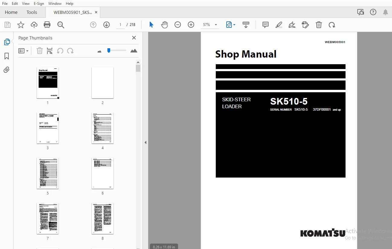
KOMATSU SK510-5 SKID-STEER LOADER SHOP MANUAL WEBM005901 – PDF DOWNLOAD
$27.95
KOMATSU SK510-5 SKID-STEER LOADER SHOP MANUAL WEBM005901 – PDF DOWNLOAD
Description
KOMATSU SK510-5 SKID-STEER LOADER SHOP MANUAL WEBM005901 – PDF DOWNLOAD
FILE DETAILS:
KOMATSU SK510-5 SKID-STEER LOADER SHOP MANUAL WEBM005901 – PDF DOWNLOAD
Language : English
Pages : 218
Downloadable : Yes
File Type : PDF
IMAGES PREVIEW OF THE MANUAL:
TABLE OF CONTENTS:
KOMATSU SK510-5 SKID-STEER LOADER SHOP MANUAL WEBM005901 – PDF DOWNLOAD
00 Index and foreword..............................................................  3
	Contents.......................................................................  4
	Foreword and general information...............................................  7
		Safety notice..............................................................  7
		How to read the shop manual................................................ 12
		Explanation of terms for maintenance standard.............................. 14
		Handling of hydraulic components........................................... 16
		Method of disconnecting and connecting push-pull type coupler.............. 18
		Handling of electric equipment............................................. 21
		How to read electric wire code............................................. 31
		Precautions when performing work........................................... 34
		Standard tightening torque table........................................... 37
		List of abbreviation....................................................... 41
		Conversion table........................................................... 45
01 Specification................................................................... 51
	Contents....................................................................... 52
	Specification.................................................................. 54
		Standard machine overall dimensions........................................ 54
		Machine overall dimensions with optional equipment......................... 55
		Specifications............................................................. 56
		Table of weight............................................................ 57
		Fuel, coolant and lubricants............................................... 58
	Shop Manual.................................................................... 61
10 Structure, function and maintenance standard.................................... 61
	Contents....................................................................... 62
	PTO............................................................................ 63
	Power train.................................................................... 64
	Transmission................................................................... 65
	Final drive.................................................................... 67
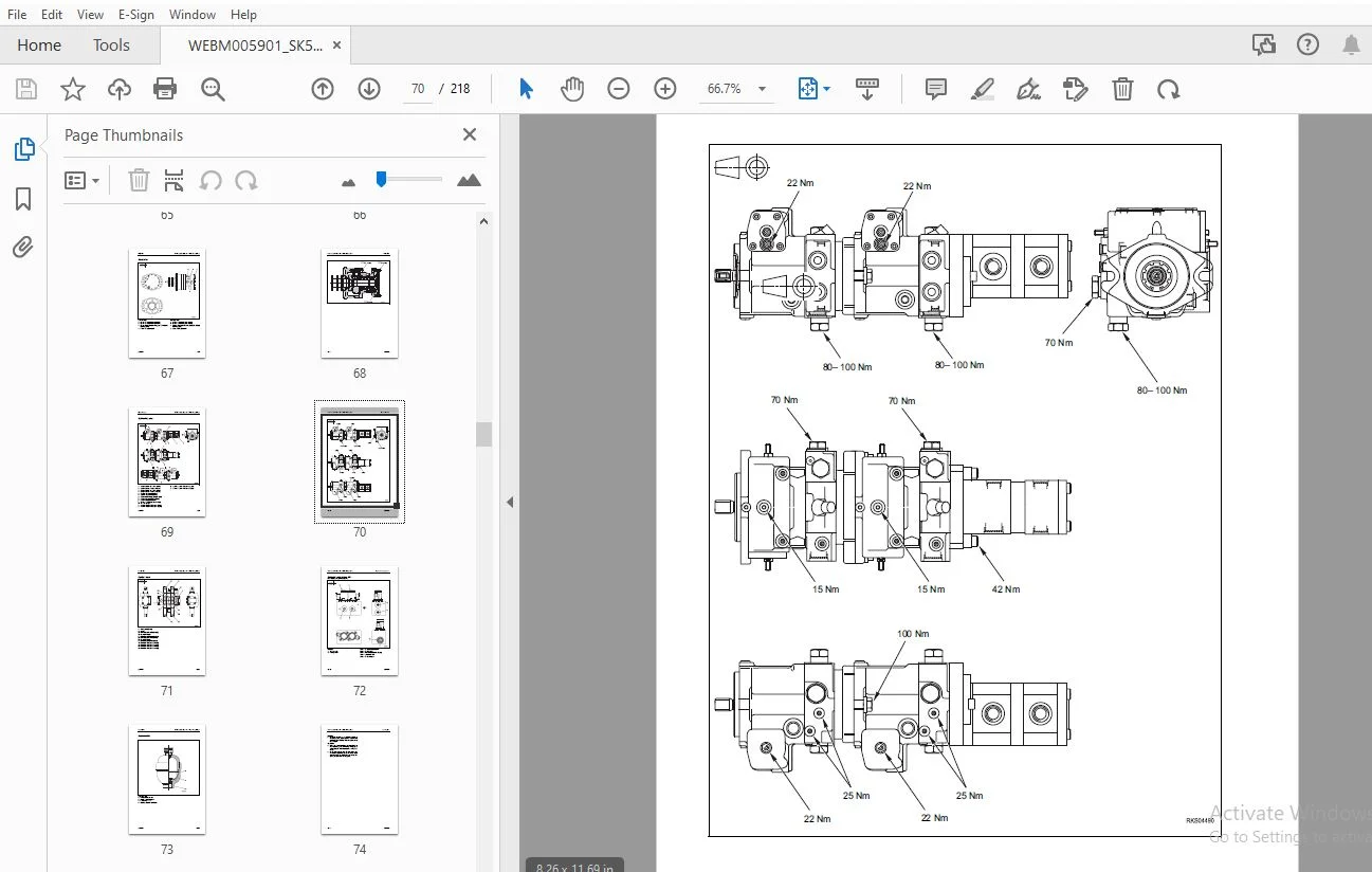
	Hydraulic pump................................................................. 69
	Control valve.................................................................. 71
	Solenoid valve group ST1....................................................... 72
	Accumulator.................................................................... 73
	R.H. PPC valve................................................................. 75
		Equipment control.......................................................... 75
	L.H. PPC valve................................................................. 76
		Travel control............................................................. 76
	Cylinders...................................................................... 77
		Lifting.................................................................... 77
		Tilt....................................................................... 78
	Work equipment................................................................. 79
	Shop Manual.................................................................... 81
20 Standard value table............................................................ 81
	Contents....................................................................... 82
	Standard value table........................................................... 83
		Engine..................................................................... 83
		Machine.................................................................... 84
30 Testing and adjusting........................................................... 91
	Contents....................................................................... 92
	Testing and adjusting.......................................................... 93
		Special tools.............................................................. 93
		Checking the engine speed.................................................. 94
		Adjustment of valve clearance.............................................. 95
		Measurement of the compression pressure.................................... 96
		Control and adjustment of the fan belt tension............................. 97
		Control and adjustment of the injection timing............................. 98
		Checking engine oil pressure...............................................100
		Adjusting the stroke of the accelerator cables.............................101
		Adjusting the position of the servo-control................................102
		Testing and adjustment of gearing chain tension............................103
		Control and regulation of the pressures in the hydraulic circuits..........104
		Testing the hydraulic pump.................................................105
		Checking the travel deviation..............................................106
		Control valve..............................................................107
		Control and regulation of the servo-control power supply...................108
		Elimination of residual pressures - pressurisation of the tank.............110
		Bleeding air from the hydraulic circuits...................................111
50 Disassembly and assembly........................................................113
	Contents.......................................................................114
	How to read the manual.........................................................115
	Coating materials list.........................................................117
	Removal and installation of engine hood........................................118
	Tilting and lowering of cab....................................................119
	Removal and installation of battery............................................121
	Removal and installation of starting motor.....................................122
	Removal and installation of alternator.........................................123
	Removal and installation of muffler............................................124
	Removal and installation of air intake filter..................................125
	Removal and installation of valve cover........................................126
	Removal and installation of nozzle holder......................................127
	Removal and installation of injection pump.....................................128
	Removal and installation of cylinder head......................................131
	Removal and installation of coolant liquid pump................................133
	Removal and installation of radiator group.....................................135
	Removal and installation of fuel tank..........................................137
	Removal and installation of cab................................................139
	Removal and installation of engine-pump group..................................142
	Removal and installation of hydraulic pump assembly............................145
	Removal and installation of gear pump..........................................147
	Removal and installation of engine-pump coupling...............................148
	Removal and installation of control valve......................................149
	Removal and installation of PPC valve..........................................150
	Removal and installation of hub wheel..........................................151
	Disassembly and assembly of wheel hub..........................................153
	Removal and installation of final drive........................................155
	Removal and installation of lift cylinder......................................156
	Removal and installation of bucket cylinder....................................157
	Disassembly and assembly of work equipment cylinders...........................159
	Removal and installation work equipment assembly...............................164
	Removal and installation of equipment support frame............................166
90 Diagrams and drawings...........................................................167
	Contents.......................................................................168
	Hydraulic diagrams.............................................................169
		Hydraulic diagram (standard)...............................................169
		Hydraulic diagram (road homologation)......................................171
	Electrical circuit diagrams....................................................173
		Engine line p/n 37D-06-11310 (1/3).........................................173
		Engine line p/n 37D-06-11310 (2/3).........................................175
		Engine line p/n 37D-06-11310 (3/3).........................................177
		Frame line p/n 37D-06-11330 (1/2)..........................................179
		Frame line p/n 37D-06-11330 (2/2)..........................................181
		Cabin line p/n 37D-06-11730 (1/4)..........................................183
		Cabin line p/n 37D-06-11730 (2/4)..........................................185
		Cabin line p/n 37D-06-11730 (3/4)..........................................187
		Cabin line p/n 37D-06-11730 (4/4)..........................................189
		Cabin line p/n 37D-06-11731 (1/4)..........................................191
		Cabin line p/n 37D-06-11731 (2/4)..........................................193
		Cabin line p/n 37D-06-11731 (3/4)..........................................195
		Cabin line p/n 37D-06-11731 (4/4)..........................................197
		Cabin line p/n 37D-06-11732 (1/4)..........................................199
		Cabin line p/n 37D-06-11732 (2/4)..........................................201
		Cabin line p/n 37D-06-11732 (3/4)..........................................203
		Cabin line p/n 37D-06-11732 (4/4)..........................................205
		Top-cabin light standard p/n 37A-06-11471 (1/2)............................207
		Top-cabin light standard p/n 37A-06-11471 (2/2)............................209
		Top-cabin light road homologation p/n 37A-06-11391 / 37A-06-11392 (1/2)....211
		Top-cabin light road homologation p/n 37A-06-11391 / 37A-06-11392 (2/2)....213
		Komtrax line p/n 42N-06-13720 (1/2)........................................215
		Komtrax line p/n 42N-06-13720 (2/2)........................................217
DESCRIPTION:
KOMATSU SK510-5 SKID-STEER LOADER SHOP MANUAL WEBM005901 – PDF DOWNLOAD
1. General precautions
1) Before performing any greasing or repairs, read all the safety labels stuck to the machine. For the locations of the safety labels and detailed explanation of precautions, see the Operation and Maintenance Manual.
2) Locate a place in the repair workshop to keep tools and removed parts. Always keep the tools and parts in their correct places. Always keep the work area clean and make sure that there is no dirt, water, or oil on the floor. Smoke only in the areas provided for smoking. Never smoke while working.
3) When performing any operation, always wear safety shoes and helmet. Do not wear loose work clothes, or clothes with buttons missing.
A Always wear the safety glasses when hitting parts with a hammer.
B Always wear the safety glasses when grinding parts with a grinder, etc.
4) When performing any operation with two or more workers, always agree on the operating procedure before starting. Always inform your fellow workers before starting any step of the operation. Before starting work, hang UNDER REPAIR warning tag in the operator’s compartment.
5) Only qualified workers must perform the work and operation which require license or qualification.
6) Keep all tools in good condition, learn the correct way to use them, and use the proper ones. Before starting work, thoroughly check the tools, machine, forklift truck, service car, etc.
7) If welding repairs are needed, always have a trained and experienced welder perform the work. When performing welding work, always wear welding gloves, apron, shielding goggles, cap and other clothes suited for welding work.
8) Before starting work, warm up your body thoroughly to start work under good condition.
9) Avoid continuing work for long hours and take rests at proper intervals to keep your body in good condition and at the provided place.
S.S 20/12/24



