
Trusted Business
Verified & Licensed
Virus Free Files
100% Safe Downloads
Secure Payment
SSL Protected
Instant Delivery
Available Immediately
Sale!


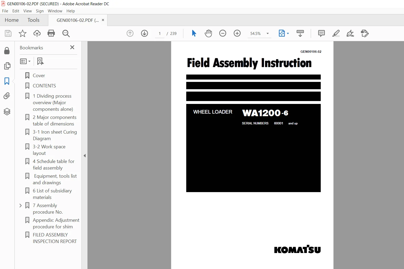
Komatsu WA1200-6 Wheel Loader Field Assembly Instruction Manual 60001 & UP – PDF DOWNLOAD
Original price was: $36.95.$16.95Current price is: $16.95.
Komatsu WA1200-6 Wheel Loader Field Assembly Instruction Manual
Book Code: GEN00106-02
SERIAL NUMBERS 60001 and up
Instant PDF Download
Available immediately
Save to Your Device
Download & keep forever
Antivirus Scanned
100% virus-free
Trusted Worldwide
175,000+ customers
Description
Komatsu WA1200-6 Wheel Loader Field Assembly Instruction Manual
FILE DETAILS:
Komatsu WA1200-6 Wheel Loader Field Assembly Instruction Manual
Brands: Komatsu
Equipment Type: Wheel Loader
Manuals Type: Field Assembly Instruction Manual
Machine Model: WA1200-6
Serial Number: 60001 & UP
Book Code: GEN00106-02
Language: English
Pages: 239
File Format: Portable Document Format (PDF)
KOMATSU WA1200-6 WHEEL LOADER FIELD ASSEMBLY INSTRUCTION MANUAL 60001 & UP – PDF DOWNLOAD:
IMAGES PREVIEW OF THE MANUAL:
TABLE OF CONTENTS:
Komatsu WA1200-6 Wheel Loader Field Assembly Instruction Manual
Cover.............................................................................................................  1
CONTENTS..........................................................................................................  2
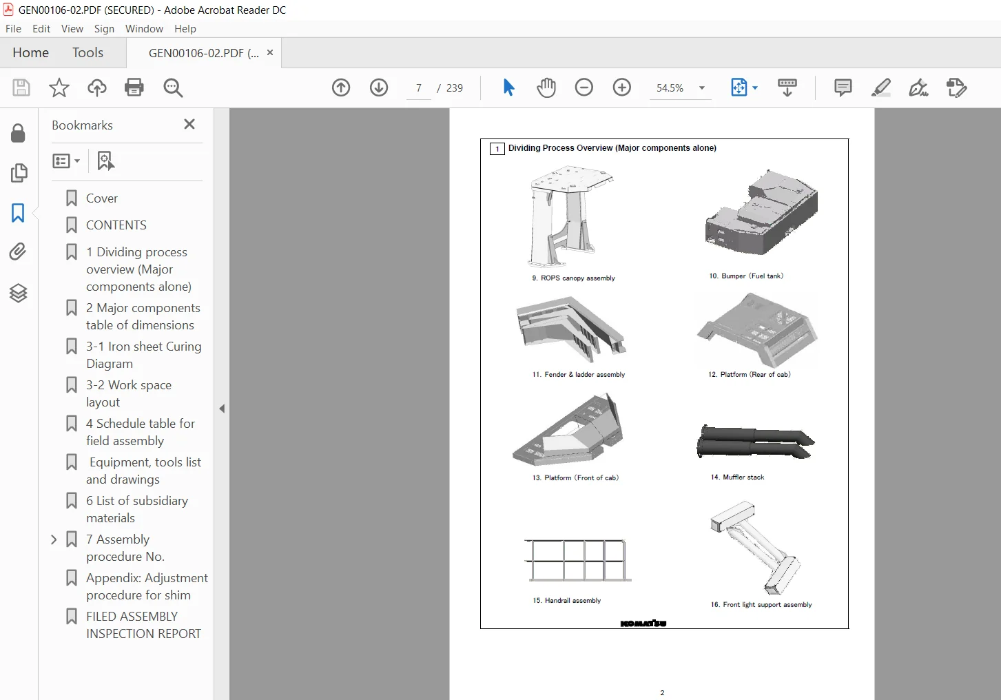
1 Dividing process overview (Major components alone)..............................................................  6
2 Major components table of dimensions............................................................................  9
3-1 Iron sheet Curing Diagram..................................................................................... 10
3-2 Work space layout............................................................................................. 10
4 Schedule table for field assembly............................................................................... 11
 Equipment, tools list and drawings............................................................................... 13
6 List of subsidiary materials.................................................................................... 23
7 Assembly procedure No...........................................................................................  0
	No.0010  Oil grease and coolant0020  Oil and coolant capacity................................................. 24
	No.0020  Oil and coolant capacity............................................................................. 25
	No.0050  Installation of General Assembling................................................................... 26
	No.0100  Setting the axle in place and assembling the support................................................. 27
	No.0110  Setting the bare machine in place.................................................................... 28
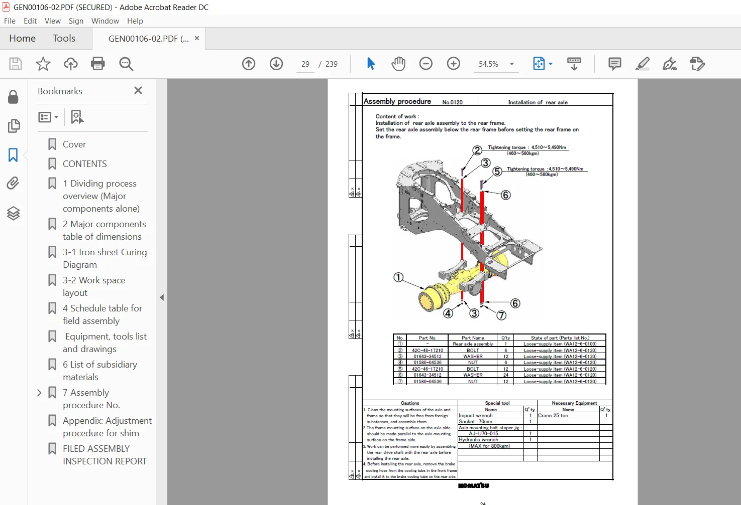
	No.0120  Installation of rear axle............................................................................ 29
	No.0130  Installation of  rear wheel and tire assembly........................................................ 30
	No.0200  Joining front and rear frames (Upper)................................................................ 31
	No.0210  Joining front and rear frames (Lower)................................................................ 32
	No.0220  Front frame and rear frame joining procedure......................................................... 33
	No.0230  Tightening center hinge bolt to specified torque..................................................... 34
	No.0250  Connecting the frame lock bar plate (Front frame side)............................................... 35
	No.0270  Installation of  steering pin........................................................................ 36
	No.0300  Installation of  front axle.......................................................................... 37
	No.0310  Installation of  front wheel and tire assembly....................................................... 38
	No.0350  Connecting the front drive shaft (Front axle between center support )................................ 39
	No.0360  Installation of  center drive shaft (Center support between transmission )........................... 40
	No.0370  Installation of rear drive shaft (Transmission between rear axle).................................... 41
	No.0380  Installation procedure of power train guard.......................................................... 42
	No.0390  Reinstallation of rear drive shaft guard............................................................. 43
	No.0400  Piping connection -1................................................................................. 44
	No.0410  Piping connection -2................................................................................. 45
	No.0450  Connecting the auto grease pipe...................................................................... 46
	No.0500  Connecting the rear axle piping...................................................................... 47
	No.0510  Connecting the front axle piping..................................................................... 48
	No.0550  Preparation for installing fuel tank and bumper assembly............................................. 49
	No.0560  Assembling the fuel tank and bumper assembly......................................................... 50
	No.0570  Connecting the fuel level sensor..................................................................... 51
	No.0580  Installation of  fuel filter and bypass filter cover................................................. 52
	No.0590  Connecting the fuel pipe............................................................................. 53
	No.0600  Assembling the floor and cab assembly................................................................ 54
	No.0610  Connecting the AJSS linkage rod (Bracket on front frame)............................................. 55
	No.0620  Connection and fixing of wiring harness under floor.................................................. 56
	No.0630  Fixing of hoses under cab............................................................................ 57
	No.0640  Connection the hose under cab - 1.................................................................... 58
	No.0650  Connection the hose under cab - 2.................................................................... 59
	No.0700  Installation of  ROPS canopy......................................................................... 61
	No.0710  Fixing of air conditioner drain hose - 1............................................................. 62
	No.0720  Fixing of air conditioner drain hose - 2............................................................. 63
	No.0730 Connecting and fixing the air conditioner drain piping under floor.................................... 64
	No.0800 Installation of battery box........................................................................... 65
	No.0810 Connecting the battery box pipe - 1................................................................... 66
	No.0820 Connecting the battery box pipe - 2................................................................... 67
	No.0830 Connecting the battery box pipe - 3................................................................... 68
	No.0840 Connecting the battery box pipe - 4................................................................... 69
	No.0850 Installation of battery support....................................................................... 70
	No.0860 Fixing of battery support pipe - 1.................................................................... 71
	No.0870 Fixing of battery support pipe - 2.................................................................... 72
	No.0880 Reinstall the battery stepNo.0880 Reinstall the battery step.......................................... 73
	No.0890 Fixing and connecting the circuit breaker pipe - 1.................................................... 74
	No.0900 Fixing and connecting the circuit breaker pipe - 2.................................................... 75
	No.0910 Fixing and connecting the circuit breaker pipe - 3.................................................... 76
	No.0920 Installation of center floor cover - 1................................................................ 77
	No.0930 Installation of platform support...................................................................... 78
	No.0940 Installation of shuttle valve line block assembly..................................................... 79
	No.0950 Installation of brake cooler tube..................................................................... 80
	No.0960 Connecting the brake cooler and torque converter cooler hose.......................................... 81
	No.1000 Installation of washer tank assembly.................................................................. 82
	No.1010 Connecting and fixing washer tank hose piping......................................................... 83
	No.1030 Connecting and fixing remote grease hoses............................................................. 84
	No.1100 Installation of air conditioner capacitor............................................................. 85
	No.1110 Connection of wiring and piping for air conditioner capacitor assembly - 1............................ 86
	No.1120 Connection of wiring and piping for air conditioner capacitor assembly - 2............................ 87
	No.1150 Connecting the heater hose piping..................................................................... 88
	No.1160 Fixing of rear wiring harness of air conditioner capacitor assembly................................... 89
	No.1170 Installation of air conditioner capacitor assembly cover.............................................. 90
	No.1180 Installation of air conditioner capacitor cover....................................................... 91
	No.1200 Connection of air-cooled brake cooler assembly........................................................ 92
	No.1210 Connection of air-cooled brake cooler assembly piping................................................. 93
	No.1250 Installation of hydraulic tank assembly............................................................... 94
	No.1260 Connecting the hydraulic tank assembly piping - 1..................................................... 95
	No.1270 Connecting the hydraulic tank assembly piping - 2..................................................... 96
	No.1280 Connecting and fixing hydraulic tank assembly piping.................................................. 97
	No.1300 Connection of breather line block piping - 1.......................................................... 98
	No.1310 Connection of breather line block piping - 2.......................................................... 99
	No.1350 Installation of brake oil tank assembly...............................................................100
	No.1360 Brake oil tank assembly drain hose....................................................................101
	No.1370 Connecting the brake oil tank hose....................................................................102
	No.1380 Connecting and fixing brake oil tank wiring harness...................................................103
	No.1400 Installation of left floor cover......................................................................104
	No.1410 Installation of right floor cover.....................................................................105
	No.1450 Installation of center floor cover - 2................................................................106
	No.1500 Connecting the engine drain tube......................................................................107
	No.1550 Installation of hydraulic breather box, pipe connection and fixing....................................108
	No.1580 Installation of air conditioner hose..................................................................109
	No.2000 Installation of auto grease pump......................................................................110
	No.2010 Installation of auto grease pump pressure switch......................................................111
	No.2020 Fixing and connecting the auto grease pump pipe.......................................................112
	No.2030 Installation of auto grease pump pressure switch......................................................113
	No.2040 Connecting and fixing auto grease pump wiring harness.................................................114
	No.2050 Installation of auto grease pump cover................................................................115
	No.2060 Fixing of auto grease pump piping - 1.................................................................116
	No.2070 Fixing of auto grease pump piping - 2.................................................................117
	No.2100 Installation of duct over bulkhead assembly...........................................................118
	No.2110 Installation of air cleaner assembly (A)..............................................................119
	No.2120 Installation of air cleaner assembly (B)..............................................................120
	No.2130 Installation of air cleaner assembly (C)..............................................................121
	No.2140 Installation of air cleaner assembly (D)..............................................................122
	No.2150 Connecting the piping between air cleaner and over duct...............................................123
	No.2160 Connecting the air intake tube........................................................................124
	No.2170 Connecting and fixing air cleaner piping..............................................................125
	No.2180 Connecting the hoses between air cleaner and muffler..................................................126
	No.2190 Connecting the piping air cleaner and under duct......................................................127
	No.2200 Fixing of air cleaner assembly hood piping............................................................128
	No.2300 Installation of air cleaner assembly (E)..............................................................129
	No.2310 Installation of air cleaner assembly (F)..............................................................130
	No.2320 Fixing of air cleaner piping (Top hood)...............................................................131
	No.2330 Fixing of air cleaner and duct piping (Top hood)......................................................132
	No.2700 Installation of left engine side cover................................................................133
	No.2750 Installation of right engine side cover...............................................................134
	No.3200 Installation of hydraulic tank emergency ladder.......................................................135
	No.3300 Installation of steps for checking engine.............................................................136
	No.3400 Installation of rear bumper handrail - 1..............................................................137
	No.3410 Installation of rear bumper handrail - 2..............................................................138
	No.3500 Installation of rear bumper handrail - 3..............................................................139
	No.3600 Installation of bumper step...........................................................................140
	No.3700 Installation of bumper steps and bracket..............................................................141
	No.3800 Installation of hood handrail - 1.....................................................................142
	No.3810 Installation of hood handrail - 2.....................................................................143
	No.4000 Installation of side work lamp........................................................................144
	No.4200 Installation of muffler pipe..........................................................................145
	No.4250 Installation of floor skirt...........................................................................146
	No.4270 Installation of left platform under cover.............................................................147
	No.4280 Installation of floor support cover...................................................................148
	No.4300 Installation of right and left floor frame............................................................149
	No.4400 Installation of right and left floor cover............................................................150
	No.4500 Installation of floor cover...........................................................................151
	No.4600 Installation of platform cover........................................................................152
	No.4700 Installation of front service step and handrails......................................................153
	No.4800 Installation of rear service step grips...............................................................154
	No.4900 Installation of left rear side floor..................................................................155
	No.5000 Installation of left rear ladder......................................................................156
	No.5100 Installation of left rear ladder cover................................................................157
	No.5200 Installation of left rear ladder handrail.............................................................158
	No.5300 Installation of front light support and connecting the wiring harness.................................159
	No.5400 Installation of front fender..........................................................................160
	No.5500 Installation of left front fender handrail............................................................161
	No.5600 Installation of right front fender handrail...........................................................162
	No.5700 Installation of rear under mirror.....................................................................163
	No.5800 Installation of left floor frame handrail.............................................................164
	No.5900 Installation of right floor frame handrail - 1........................................................165
	No.5910 Installation of floor frame rearview mirror - 2.......................................................166
	No.6000 Installation of floor frame rearview mirror - 1.......................................................167
	No.6010 Installation of floor frame rearview mirror - 2.......................................................168
	No.6050 Installation of handrail pipe.........................................................................169
	No.6100 Installation of bumper handrail.......................................................................170
	No.6200 Installation of floor mat.............................................................................171
	No.6300 Installation of rear combination lamp.................................................................172
	No.7500 Installation of yellow rotary lamp (Yellow rotary lamp : If equipment)................................173
	No.8000 Precautions for piping air conditioner................................................................174
	No.8100 Refueling and water supply............................................................................175
	No.8110 Adding hydraulic oil..................................................................................176
	No.8300 Install and adjustment procedure of mirror............................................................177
	No.8350 Adjustment procedure for under mirror.................................................................178
	No.8400 Neutral Adjustment of AJSS............................................................................179
	No.8600 Procedure of bleeding air from piston pump............................................................180
	No.8700 Adjustment procedure for joystick stopper bolt........................................................181
	No.8800 Adjustment of belt tension / Precaution and checking quantity refrigerant.............................182
	No.8900 Connecting the battery box ground.....................................................................183
	No.8910 Connecting the battery box pipe - 5...................................................................184
	No.9000 Starting engine.......................................................................................185
	No.9010 Adding brake oil and brake cooling oil and bleeding air...............................................186
	No.9020 Procedure for supplying transmission oil for first time and bleeding air from transmission circuit....187
	No.9030 Procedure of adding oil and adjusting oil level.......................................................188
	No.9040 Bleeding air from auto grease line - 1................................................................189
	No.9050 Bleeding air from auto grease line - 2................................................................190
	No.9100 Installation of boom and bellcrank assembly...........................................................191
	No.9110 Installation of lift cylinder (Lift arm side).........................................................192
	No.9120 Installation of dump cylinder and bellcrank assembly..................................................193
	No.9130 Installation of tooth.................................................................................194
	No.9140 Installation of bucket assembly.......................................................................195
	No.9200 Adjustment procedure for shim on work equipment pin...................................................196
	No.9210 Assembly procedure for lubricated pin.................................................................197
	No.9230 Adjusting bucket positioner...........................................................................198
	No.9240 Initialization and adjustment procedure for boom angle sensor.........................................199
	No.9300 Running-in............................................................................................200
	No.9500 Initialization of multi monitor (Input of service ID).................................................201
	No.9510 Initialization of multi-monitor (Optional setting)....................................................202
	No.9520 Initialization of multi-monitor (Introduction of adjustment menu).....................................203
	No.9530 Initialization of multi-monitor (Adjustment menu: AJSS)...............................................204
	No.9540 Initialization of multi-monitor (Adjustment menu: Transmission).......................................205
	No.9550 Initialization of multi-monitor (Adjustment menu: Load meter).........................................206
	No.9560 Initialization of multi-monitor (Adjustment menu: Payload)............................................207
	No.9570 Initialization of multi-monitor (Adjustment menu: Work equipment - 1).................................208
	No.9580 Initialization of multi-monitor (Adjustment menu: Work equipment - 2).................................209
	No.9590 Initialization of multi-monitor (Adjustment menu: Work equipment - 3).................................210
Appendix: Adjustment procedure for shim...........................................................................211
FILED ASSEMBLY INSPECTION REPORT..................................................................................224
PLEASE NOTE:
- This is the SAME MANUAL used by the dealerships to diagnose your vehicle
- No waiting for couriers / posts as this is a PDF manual and you can download it within 2 minutes time once you make the payment.
- Your payment is all safe and the delivery of the manual is INSTANT – You will be taken to the DOWNLOAD PAGE.
- So have no hesitations whatsoever and write to us about any queries you may have : heydownloadss @gmail.com



