Komatsu WA200-6 Wheel Loader Shop Manual SEN06520-06 PDF
$38.95
Komatsu WA200-6 Wheel Loader Shop Manual SEN06520-06 – PDF DOWNLOAD
SERIAL NUMBERS 72001 and up
Description
Komatsu WA200-6 Wheel Loader Shop Manual SEN06520-06 – PDF DOWNLOAD
FILE DETAILS:
Komatsu WA200-6 Wheel Loader Shop Manual SEN06520-06 – PDF DOWNLOAD
Language : English
Pages : 1232
Downloadable : Yes
File Type : PDF
IMAGES PREVIEW OF THE MANUAL:
TABLE OF CONTENTS:
Komatsu WA200-6 Wheel Loader Shop Manual SEN06520-06 – PDF DOWNLOAD
SERIAL NUMBERS 72001 and up
Cover 1
00 Index and foreword 3
Index and foreword 4
Index 4
Foreword, safety and general information 13
Important safety notice 13
How to read the shop manual 20
Explanation of terms for maintenance standard 22
Handling equipment of fuel system devices 24
Handling of intake system parts 25
Handling of hydraulic equipment 26
Method of disconnecting and connecting of push-pull type coupler 28
Handling of electrical equipment 31
How to read electric wire code 39
Precautions when performing operation 42
Practical use of KOMTRAX 47
Standard tightening torque table 48
List of Abbreviation 54
Conversion table 58
01 Specification 63
Specification 65
Specification dimension drawing 65
Specifications 66
Weight table 70
Table of fuel, coolant and lubricants 72
10 Structure, function and maintenance standard 73
Engine and cooling system 76
Engine mount and transfer mount 76
Damper 77
Cooling system 78
Cooling system hydraulic piping diagram 79
Cooling fan motor 81
Power train 89
Power train 89
Power train system diagram 90
Drive shaft 92
HST hydraulic piping diagram 93
HST pump 94
HST motor 102
Transfer 108
Clutch solenoid valve 119
Axle 120
Differential 122
Torque proportioning differential 127
Limited slip differential 130
Final drive 134
Steering system 139
Steering piping diagram 139
Steering column 140
Priority valve 141
Orbit-roll valve 144
2-way restrictor valve 152
Cushion valve 153
Steering cylinder 154
Emergency steering piping diagram 156
Emergency steering valve 157
Steering relief valve 160
Brake system 161
Brake piping diagram 161
Charge valve 162
Brake valve 166
Inching valve 170
Accumulator (for brake) 171
Slack adjuster 172
Brake 174
Parking brake control 179
Parking brake 180
Undercarriage and frame 182
Axle mount and center hinge pin 182
Hydraulic system 188
Work equipment hydraulic piping diagram 188
Work equipment control lever linkage 190
Hydraulic tank 192
Quadruple gear pump 194
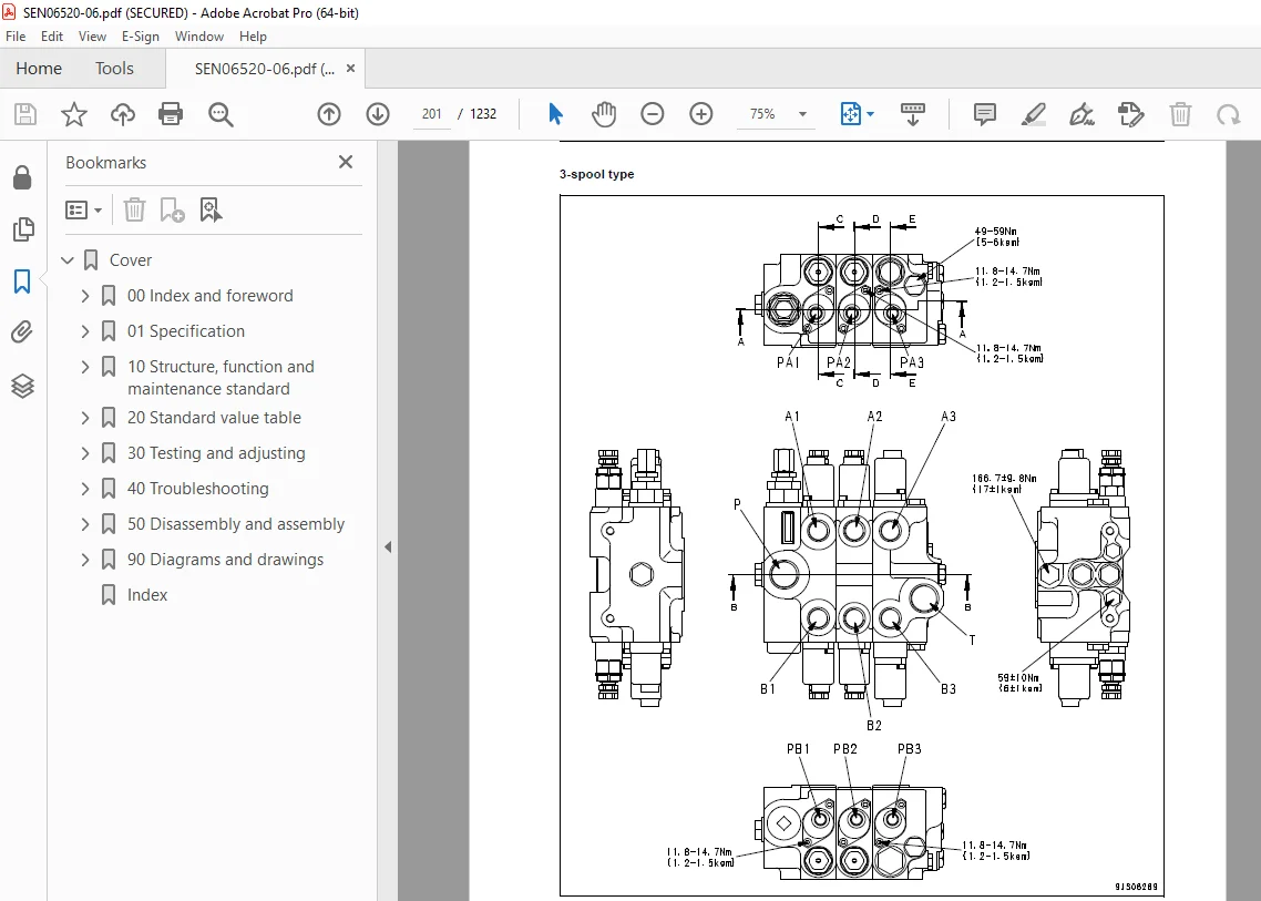
Work equipment control valve 197
PPC valve 214
Lock valve 222
Accumulator (for PPC circuit) 223
Work equipment 224
Work equipment linkage 224
Bucket 226
Bucket positioner and boom kick-out 228
Work equipment cylinder 236
Cab and its attachments 238
Cab 238
Air conditioner 240
Electrical system 252
Machine monitor system 252
Machine monitor 256
Electrical system (HST controller system) 277
HST controller 292
KOMTRAX system 294
Engine starting circuit 298
Engine stopping circuit 300
Preheating circuit 301
Engine output derating function 302
Automatic warm-up function 302
Parking brake circuit 303
Max traction switch 305
Sensor 306
20 Standard value table 313
Standard service value table 315
Standard service value table for engine 315
Standard service value table for chassis 316
30 Testing and adjusting 323
Related information on testing and adjusting 326
Tools for testing, adjusting, and troubleshooting 326
Sketches of special tools 331
Engine and cooling system 332
Measuring engine speed 332
Measuring exhaust gas color 334
Adjusting valve clearance 335
Measuring compression pressure 337
Measuring blowby pressure 340
Testing engine oil pressure 341
Measuring intake air (boost) pressure 342
Handling fuel system equipment 343
Releasing residual pressure in fuel system 343
Measuring fuel pressure 344
Measuring fuel return rate and leakage 346
Bleeding air from fuel circuit 350
Checking leakage in fuel system 351
Handling cylinder cut-out mode operation 352
Handling no-injection cranking operation 352
Handling controller voltage circuit 353
Check of muffler and muffler stack for looseness and damage 353
Check of muffler function 354
Check of installed condition of cylinder head and manifolds 354
Check of engine piping for damage and looseness 355
Testing and adjusting air conditioner compressor belt tension 355
Replacing alternator belt 356
Power train 357
Testing and adjusting HST oil pressure 357
Testing clutch control pressure 361
Steering system 362
Testing steering wheel 362
Testing and adjusting steering oil pressure 364
Bleeding air from steering circuit 366
Brake system 367
Measuring brake pedal 367
Testing and adjusting brake pedal linkage 368
Measuring brake performance 369
Testing and adjusting accumulator charge pressure 370
Testing wheel brake oil pressure 372
Testing wear of brake disc 375
Bleeding air from wheel brake circuit 376
Releasing residual pressure in brake accumulator circuit 377
Testing parking brake performance 378
Testing and adjusting parking brake control cable 379
Hydraulic system 380
Testing hydraulic fan 380
Testing and adjusting work equipment hydraulic pressure 382
Testing work equipment PPC oil pressure 384
Bleeding air from hydraulic circuit 386
Releasing remaining pressure in hydraulic circuit 387
Work equipment 388
Testing and adjusting bucket positioner 388
Testing and adjusting boom kick-out switch 390
Checking proximity switch operation pilot lamp 391
Cab and its attachments 392
Checking operating force of accelerator pedal 392
Checking directional lever 393
Measuring work equipment control lever 394
Electrical system 395
Procedure for testing diodes 395
Preparation work for troubleshooting for electric system 397
Starting KOMTRAX terminal operations 401
Indicator lamps of KOMTRAX terminal 408
Adjusting machine monitor 414
Adjusting replaced, reassembled or added sensor, controller, etc with machine monitor 415
Special functions of machine monitor (EMMS) 417
Pm clinic 468
Pm clinic inspection chart 468
40 Troubleshooting 471
Related information on troubleshooting 477
Points to remember when performing troubleshooting 477
How to proceed in troubleshooting 479
Testing before troubleshooting 481
Classification and procedures of troubleshooting 482
Phenomena looking like troubles and troubleshooting Nos 486
Information in troubleshooting table 488
Troubleshooting method for open circuit in wiring harness of pressure sensor system 490
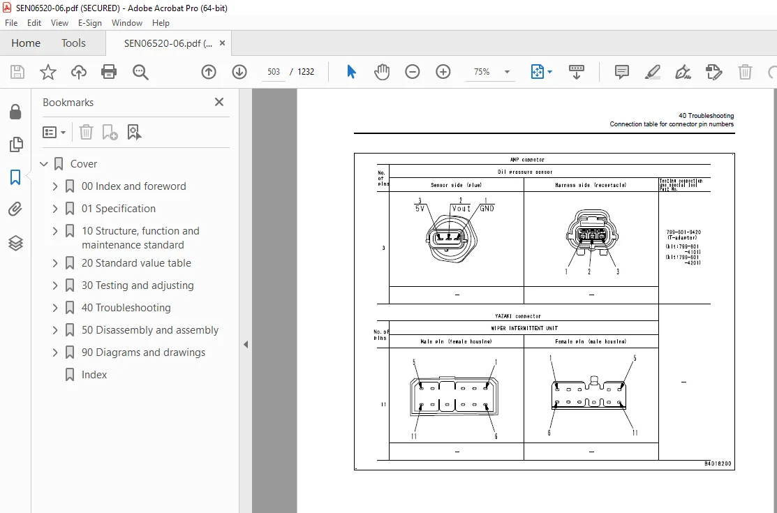
Connection table for connector pin numbers 493
T- branch box and T- branch adapter table 529
Fuse location 533
Failure codes table 537
Troubleshooting by failure code (Display of code) 544
Failure code [2G40ZG] Brake : Low oil pressure 544
Failure code [6091NX] HST filter : Clogging 546
Failure code [989FN1] Travel speed : Overrun alarm 548
Failure code [AB00L6] Alternator R system : Hot short 550
Failure code [AB00MA] Alternator R system : Ground fault/ Open circuit/Low charge level 552
Failure code [B@BAZG] Engine : Low oil pressure 554
Failure code [B@BCNS] Engine : Overheat 555
Failure code [B@BCZK] Engine : Low coolant level 556
Failure code [B@C6NS] Front brake : Oil temperature overheat 558
Failure code [B@CRNS] HST : Oil temperature overheat 559
Failure code [CA111] Engine controller : Internal failure 560
Failure code [CA115] Engine Ne and Bkup speed sensor : Error 561
Failure code [CA122] Charge air pressure sensor : High error 562
Failure code [CA123] Charge air pressure sensor : Low error 564
Failure code [CA131] Throttle sensor : High error 566
Failure code [CA132] Throttle sensor : Low error 568
Failure code [CA144] Coolant temperature sensor : High error 570
Failure code [CA145] Coolant temperature sensor : Low error 572
Failure code [CA153] Charge air temperature sensor : High error 574
Failure code [CA154] Charge air temperature sensor : Low error 576
Failure code [CA155] Charge air temperature : High speed derate 578
Failure code [CA187] Sensor power supply 2 voltage : Low error 580
Failure code [CA221] Ambient pressure sensor : High error 582
Failure code [CA222] Ambient pressure sensor : Low error 584
Failure code [CA227] Sensor power supply 2 voltage : High error 586
Failure code [CA234] Engine : Overspeed 586
Failure code [CA238] Ne Speed sensor : Power supply voltage error 587
Failure code [CA271] IMV (IMA): Short circuit 588
Failure code [CA272] IMV (IMA): Open circuit 590
Failure code [CA322] Injector #1 system : Open/Short circuit 592
Failure code [CA324] Injector #3 system : Open/Short circuit 594
Failure code [CA331] Injector #2 system : Open/Short circuit 596
Failure code [CA332] Injector #4 system : Open/Short circuit 598
Failure code [CA342] Engine controller : Data mismatching 600
Failure code [CA351] Injectors Drive Circuit : Error 601
Failure code [CA352] Sensor power supply 1 voltage : Low error 602
Failure code [CA386] Sensor power supply voltage 1 : High error 604
Failure code [CA428] Water-in-fuel sensor : High error 606
Failure code [CA429] Water-in-fuel sensor : Low error 608
Failure code [CA431] Idle validation switch : Error 610
Failure code [CA432] Idle validation switch : Action error 613
Failure code [CA435] Engine oil pressure switch : Error 616
Failure code [CA441] Power supply voltage : Low error 618
Failure code [CA442] Power supply voltage : High error 621
Failure code [CA449] Common rail pressure : High error 2 622
Failure code [CA451] Common rail pressure sensor : High error 624
Failure code [CA452] Common rail pressure sensor : Low error 626
Failure code [CA488] Charge temperature : High torque derate 628
Failure code [CA553] Common rail pressure : High error 629
Failure code [CA559] Supply Pump : Low rail pressure 1 630
Failure code [CA689] Engine Ne speed sensor : Error 632
Failure code [CA731] Engine Bkup speed sensor : Phase error 634
Failure code [CA757] Engine controller : Lost of all data 635
Failure code [CA778] Engine Bkup speed sensor : Error 636
Failure code [CA1633] KOMNET : Error 639
Failure code [CA2185] Throttle sensor power supply voltage : High error 640
Failure code [CA2186] Throttle sensor power supply voltage : Low error 642
Failure code [CA2249] Supply pump : Low rail pressure 2 644
Failure code [CA2311] IMV (IMA) Solenoid : Error 645
Failure code [CA2555] Intake heater relay : Open circuit 646
Failure code [CA2556] Intake heater relay : Short circuit 649
Failure code [D160KY] Backup alarm/lamp relay 1 circuit: Hot short 652
Failure code [D1B0KA] HST safety relay: Disconnection 654
Failure code [D1B0KB] HST safety relay: Ground fault 656
Failure code [D1B0KY] HST safety relay: Hot short 658
Failure code [D5ZHL6] IGN C system: Ground fault/ Disconnection 660
Failure code [DAF3KK] UNSW power supply: Ground fault/ Disconnection 664
Failure code [DAFRKR] Machine monitor CAN-NET Signal: Disconnection 667
Failure code [DAJ0KK] HST controller power supply: Low voltage 668
Failure code [DAJ0KT] HST controller memory (EEPROM): Abnormality 671
Failure code [DAJ1L4] HST controller main power supply line: Disconnection/Ground fault 672
Failure code [DAJ1L6] HST controller main power supply line: Hot short 675
Failure code [DAJ2KK] Controller solenoid power supply: Low voltage 678
Failure code [DAJ2L3] HST controller load power supply holding line: Hot short 681
Failure code [DAJ2L4] HST controller load power supply holding line: Disconnection/Ground fault 684
Failure code [DAJ5KX] Sensor 5V power supply: Out of input range 687
Failure code [DAJ9KQ] HST controller : Disagreement in model selection 689
Failure code [DAJRKR] HST controller CAN-NET signal: Disconnection 690
Failure code [DAJRMA] HST controller: Disagreement in option selection 697
Failure code [DB2RKR] Engine controller CAN-NET signal: Disconnection 698
Failure code [DD1NL4] Fan Auto Reverse Switch Signal : Abnormality 704
Failure code [DD1NLD] Fan Reverse Switch Signal: Abnormal 707
Failure code [DDB6KA] Parking brake reminder signal: Disconnection/Hot short 710
Failure code [DDB6KB] Parking brake indicator signal: Ground fault 714
Failure code [DDB6KZ] Parking brake indicator signal or parking brake reminder signal : Failure 717
Failure code [DDB6L0] Parking brake reminder signal: Ground fault 720
Failure code [DDB6L4] Parking brake indicator signal: Disconnection/Hot short 723
Failure code [DDD7KX] Travel speed control dial signal: Disconnection/Ground fault 728
Failure code [DDD7KY] Travel speed control dial signal: Hot short 730
Failure code [DDE5MA] Emergency steering operation switch: Disconnection 732
Failure code [DDK6KA] FNR lever: Disconnection/Ground fault 734
Failure code [DDK6KY] FNR lever: Hot short 738
Failure code [DDS5L6] Steering: Low oil pressure (Operation of emergency steering) 740
Failure code [DF10KA] Travel speed range selector switch: Disconnection/Ground fault 742
Failure code [DF10KB] Travel speed range selector switch: Hot short 747
Failure code [DGH1KX] HST oil temperature sensor: Ground fault 752
Failure code [DGR2KB] Brake oil temperature sensor: Ground fault 754
Failure code [DGR2KZ] Brake oil temperature sensor : Disconnection/Hot short 756
Failure code [DHH1KX] HST oil pressure sensor: Disconnection/Ground fault 758
Failure code [DHH1KY] HST oil pressure sensor: Hot short 760
Failure code [DHTCL6] HST filter clogging sensor: Functional defect 762
Failure code [DJF1KA] Fuel level sensor: Disconnection/Hot short 764
Failure code [DLT3KX] Travel speed sensor B: Abnormality 766
Failure code [DLT4KX] Travel speed sensor A: Abnormality 772
Failure code [DLT4LC] Travel speed sensor A & B: Abnormality 774
Failure code [DV00KY] Alarm buzzer: Hot short 776
Failure code [DW26KA] Motor 2 solenoid: Disconnection/Ground fault 778
Failure code [DW26KY] Motor 2 solenoid: Hot short 780
Failure code [DW7BKY] Fan reverse solenoid circuit: Hot short 782
Failure code [DW7BKZ] Fan reverse solenoid circuit: Disconnection/Ground fault 784
Failure code [DX16KA] Fan EPC solenoid: Disconnection 786
Failure code [DX16KB] Fan EPC solenoid: Ground fault 787
Failure code [DX16KY] Fan EPC solenoid: Hot short 788
Failure code [DX19KA] Motor 1 solenoid: Disconnection 790
Failure code [DX19KB] Motor 1 solenoid: Ground fault 792
Failure code [DX19KY] Motor 1 solenoid: Hot short 794
Failure code [DX20KA] Clutch EPC solenoid: Disconnection 796
Failure code [DX20KB] Clutch EPC solenoid: Ground fault 798
Failure code [DX20KY] Clutch EPC solenoid: Hot short 800
Failure code [DXH7KB] Reverse solenoid : Ground fault 802
Failure code [DXH7KZ] Reverse solenoid: Disconnection/Hot short 804
Failure code [DXH8KB] Forward solenoid : Ground fault 806
Failure code [DXH8KZ] Forward solenoid: Disconnection/Hot short 808
Failure code [J141N1] Steering pump: Overrun alarm 810
Failure code [M100N1] HST pump: Overrun alarm 810
Failure code [M400N1] Motor 1: Overrun alarm 811
Troubleshooting of electrical system (E-mode) 812
E-1 Engine does not start 812
E-2 Preheater does not operate normally 820
E-3 When starting switch is turned to ON position, nothing is displayed on machine monitor 825
E-4 Travel speed is not displayed correctly 829
E-5 Travel speed is low or high 830
E-6 Boom kick-out does not work or is not reset 833
E-7 Bucket positioner does not work or is not reset 837
E-8 Boom FLOAT holding does not work or is not reset 841
E-9 Directional selection does not work normally 847
E-10 Wipers do not operate 852
E-11 Window washer does not operate 858
E-12 Headlamp, clearance lamp, tail lamp or license-plate lamp does not light up or does not go out 862
E-13 Working lamp does not light up or does not go out 872
E-14 Turn signal and hazard lamp do not light up or do not go out 878
E-15 Stop lamp does not light up or remains lighting up 888
E-16 Backup lamp does not light or it keeps lighting up 891
E-17 Backup alarm does not sound or does not stop sounding 894
E-18 Horn does not sound or does not stop sounding 896
E-19 Alarm buzzer does not sound or does not stop sounding 898
E-20 Troubleshooting of air conditioner 900
E-21 KOMTRAX system does not operate normally 922
Troubleshooting of hydraulic and mechanical system (H-mode) 926
Method of using troubleshooting chart 926
Failure code and cause table 928
H-1 The machine does not start 930
H-2 The travel speed is slow 931
H-3 The traction force is weak 932
H-4 Engine stalls when traveling or engine speed drops excessively 933
H-5 Speed range is not shifted 934
H-6 The steering wheel does not turn 935
H-7 The steering wheel is heavy 936
H-8 Steering wheel shakes or jerks 937
H-9 Machine deviates naturally to one side when traveling 937
H-10 The brake does not work or does not work well 938
H-11 The brake is not released or is dragged 939
H-12 The boom does not rise or lower 940
H-13 The boom moves slowly or the lift arm rising force is insufficient 941
H-14 When rising, the boom comes to move slowly at specific height 942
H-15 The lift cylinder cannot hold down the bucket (The bucket rises in the air) 942
H-16 Hydraulic drifts of the boom are large 942
H-17 The boom wobbles during operation 942
H-18 When the control lever is switched from “HOLD” to “RAISE,” the boom falls temporarily 943
H-19 The bucket does not tilt back 944
H-20 The bucket moves slowly or the tilting-back force is insufficient 945
H-21 The bucket comes to operate slowly in the midst of tilting-back 946
H-22 The bucket cylinder cannot hold down the bucket 946
H-23 Hydraulic drifts of the bucket occur often 946
H-24 The bucket wobbles during travel with load (The work equipment valve is set to “HOLD”) 946
H-25 When the control lever is switched from “HOLD” to “TILT,” the bucket falls temporarily 947
H-26 The control levers of the boom and bucket do not move smoothly and heavy 947
H-27 Fan revolution is abnormal (Fan sound/vibration is abnormally large or engine overheats) 948
Troubleshooting of engine (S-mode) 949
Method of using troubleshooting charts 949
S-1 Starting performance is poor 952
S-2 Engine does not start 953
S-3 Engine does not pick up smoothly 956
S-4 Engine stops during operations 957
S-5 Engine does not rotate smoothly 958
S-6 Engine lacks output (or lacks power) 959
S-7 Exhaust smoke is black (incomplete combustion) 960
S-8 Oil consumption is excessive (or exhaust smoke is blue) 961
S-9 Oil becomes contaminated quickly 962
S-10 Fuel consumption is excessive 963
S-11 Oil is in coolant (or coolant spurts back or coolant level goes down) 964
S-12 Oil pressure drops 965
S-13 Oil level rises (Entry of coolant or fuel) 966
S-14 Coolant temperature becomes too high (overheating) 967
S-15 Abnormal noise is made 968
S-16 Vibration is excessive 969
50 Disassembly and assembly 971
General information on disassembly and assembly 973
How to read this manual 973
Coating materials list 975
Special tool list 979
Sketches of special tools 983
Engine and cooling system 994
Removal and installation of fuel supply pump assembly 994
Removal and installation of fuel injector assembly 998
Removal and installation of cylinder head assembly 1006
Removal and installation engine hood assembly 1020
Removal and installation of radiator 1024
Removal and installation of air aftercooler 1027
Removal and installation of hydraulic oil cooler assembly 1029
Removal and installation of engine assembly 1031
Removal and installation of engine front oil seal assembly 1038
Removal and installation of engine rear oil seal assembly 1042
Removal and installation of cooling fan and fan motor assembly 1045
Removal and installation of fuel tank assembly 1048
Power train 1050
Removal and installation of transfer assembly 1050
Disassembly and assembly of transfer assembly 1054
Removal and installation of parking brake assembly 1081
Disassembly and assembly of parking brake assembly 1077
Removal and installation of front axle assembly 1082
Removal and installation of rear axle assembly 1084
Disassembly and assembly of axle housing assembly 1087
Disassembly and assembly of differential assembly 1095
Undercarriage and frame 1122
Removal and installation of center hinge pin 1122
Removal and installation of counterweight assembly 1131
Hydraulic system 1133
Removal and installation of HST pump and quadruple gear pump assembly 1133
Removal and installation of HST motor 1 assembly 1137
Removal and installation of HST motor 2 assembly 1139
Removal and installation of work equipment control valve assembly 1141
Removal and installation of hydraulic tank 1143
Disassembly and assembly of hydraulic cylinder assembly 1145
Work equipment 1149
Removal and installation of work equipment assembly 1149
Cab and its attachments 1156
Removal and installation of operator’s cab and floor frame assembly 1156
Removal and installation of operator’s cab glass (Stuck glass) 1161
Removal and installation of operator’s seat assembly 1169
Removal and installation of air conditioner unit 1170
Electrical system 1175
Removal and installation of monitor panel 1175
Removal and installation of engine controller assembly 1177
Removal and installation of HST controller assembly 1179
Removal and installation of KOMTRAX terminal (ORBCOMM) assembly 1180
Removal and installation of KOMTRAX terminal (GPRS) assembly 1181
90 Diagrams and drawings 1183
Hydraulic diagrams and drawings 1185
Symbols used in hydraulic circuit diagrams 1185
Hydraulic circuit diagram 1187
Electrical diagrams and drawings 1189
Symbols used in electric circuit diagrams 1189
Electrical circuit diagram 1193
Electrical circuit diagram for CIS 1209
Electrical circuit diagram of engine and HST 1219
Connector list and stereogram 1221
Connector list and stereogram (CIS specification) 1223
Index 1225
DESCRIPTION:
Komatsu WA200-6 Wheel Loader Shop Manual SEN06520-06 – PDF DOWNLOAD
SERIAL NUMBERS 72001 and up
How to read the shop manual
Composition of shop manual
q This shop manual describes the technical information required for the services performed in a workshop.
The shop manual is divided into the following chapters for the convenience of use.
00. Index and foreword
q This section includes the index, foreword, safety and basic information.
01. Specification
q This section explains the specifications of the machine.
10. Structure, function and maintenance standard
q This section explains the structure and function of the machine. The section of “Structure and function”
serves not only to give an understanding for the structure of each component, but also serves as reference
material for troubleshooting.
q This section also describes the maintenance standard values for each component. This section gives the
criterion values for each component and required remedy at disassembly or maintenance.
20. Standard value table
q The standard values for a new machine and trouble shooting are indicated. This standard value table is
used for testing and adjusting, and determining a failure at troubleshooting.
30. Testing and adjusting
q This section describes the measuring tools and how to measure, and how to adjust various parts. As for
the standard value and failure criterion, see the standard value table.
40. Troubleshooting
q This section describes the troubleshooting in a suspected area when a failure occurs and the remedy for
the failure. Troubleshooting is described by each failure mode.
50. Disassembly and assembly
q This section explains the procedures for removing, installing, disassembling, and assembling each part or
component and the special tools for the works as well as precautions for doing them safely. In addition,
tightening torque, and quantity and weight of coating material, oil, grease, and coolant required for the
works are also explained.
80. Appendix
q The structure and function, testing and adjusting, and troubleshooting for all of the other components or
equipment which can not be separately classified are explained together in the appendix.
90. Diagrams and drawings
q This section gives hydraulic circuit diagrams and electrical circuit diagrams.
S.V 30/12/24


