Komatsu WA250-6 WA250PZ-6 Shop Manual VEBM610101 – PDF DOWNLOAD
$35.95
Komatsu WA250-6 WA250PZ-6 Shop Manual VEBM610101 – PDF DOWNLOAD
Description
Komatsu WA250-6 WA250PZ-6 Shop Manual VEBM610101 – PDF DOWNLOAD
FILE DETAILS:
Komatsu WA250-6 WA250PZ-6 Shop Manual VEBM610101 – PDF DOWNLOAD
Language : English
Pages : 1244
Downloadable : Yes
File Type : PDF
IMAGES PREVIEW OF THE MANUAL:
TABLE OF CONTENTS:
Komatsu WA250-6 WA250PZ-6 Shop Manual VEBM610101 – PDF DOWNLOAD
VEBM610101 1
00 Index and foreword 3
100 Index 3
Composition of shop manual 4
Table of contents 6
200 Foreword and general information 15
Safety notice 16
How to read the shop manual 21
Explanation of terms for maintenance standard 23
Handling of electric equipment and hydraulic component 25
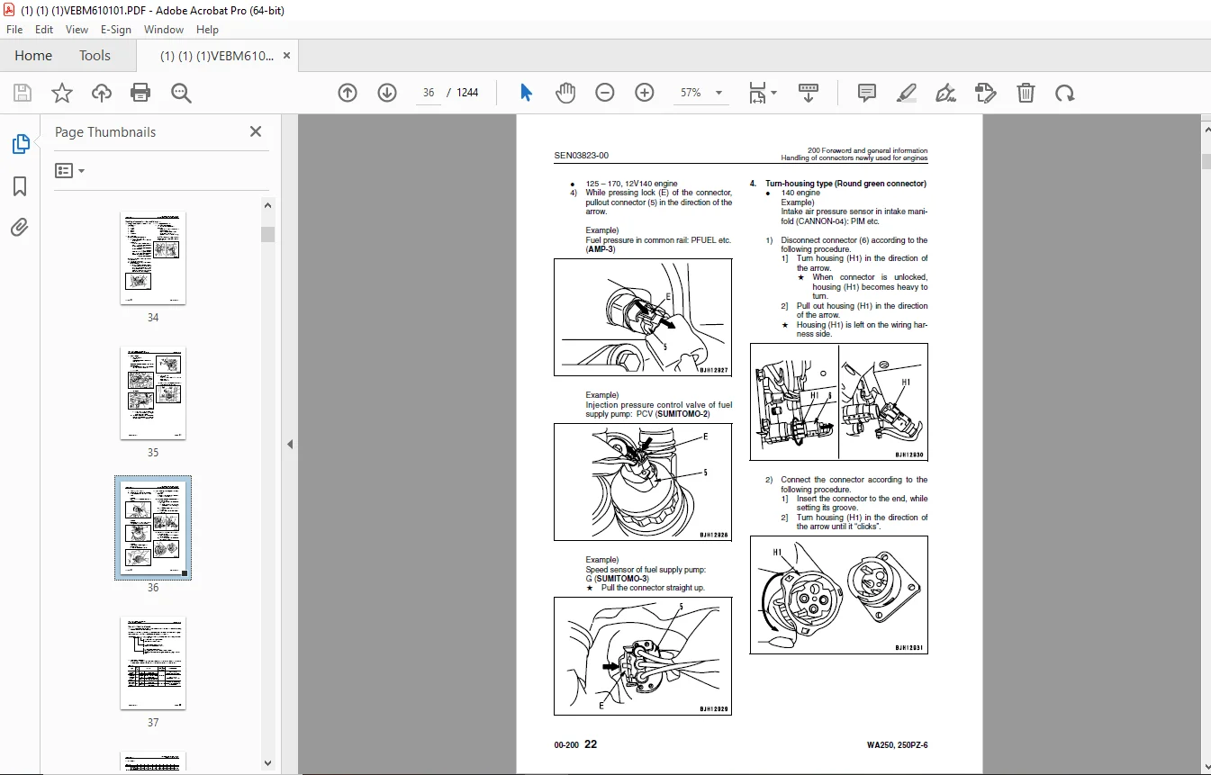
Handling of connectors newly used for engines 34
How to read electric wire code 37
Precautions when carrying out operation 40
Method of disassembling and connecting push-pull type coupler 43
Standard tightening torque table 46
Conversion table 50
01 Specification 55
100 Specification and technical data 55
Specification dimension drawing 57
Specifications 58
Weight table 62
Table of fuel, coolant and lubricants 64
10 Structure, function and maintenance standard 65
100 Engine and cooling system 65
Engine mount and transfer mount 66
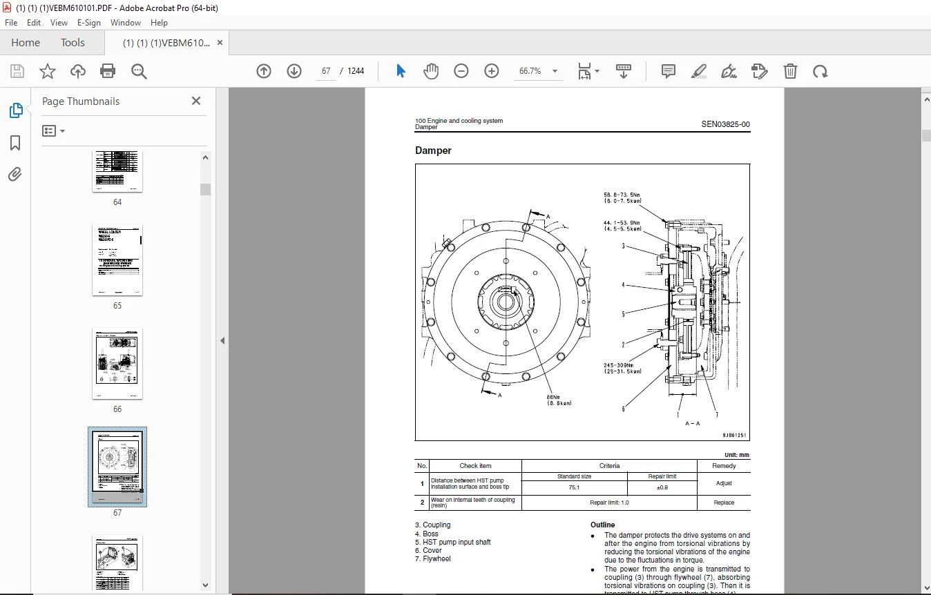
Damper 67
Cooling system 68
Cooling system hydraulic piping diagram 69
Cooling fan motor 71
200 Power train 79
Power train 81
Power train system diagram 82
Drive shaft 84
HST hydraulic piping diagram 85
HST pump 86
HST motor 94
Transfer 100
Clutch solenoid valve 111
Axle 112
Differential 114
Torque proportioning differential 119
Limited slip differential 122
Final drive 126
300 Steering system 131
Steering piping diagram 133
Steering column 134
Priority valve 135
Orbit-roll valve 138
2-way restrictor valve 146
Cushion valve 147
Steering cylinder 148
Emergency steering piping diagram 150
Emergency steering valve 151
Steering relief valve 154
400 Brake system 155
Brake piping diagram 157
Charge valve 158
Brake valve 162
Inching valve 166
Accumulator (for brake) 167
Slack adjuster 168
Brake 170
Parking brake control 175
Parking brake 176
500 Undercarriage and frame 177
Axle mount and center hinge pin 178
Tires 183
600 Hydraulic system 185
Work equipment hydraulic piping diagram 186
Work equipment control lever linkage 190
Hydraulic tank 194
4-gear pump 196
Work equipment control valve 198
PPC valve 223
Lock valve 238
Accumulator (for PPC circuit) 239
Bypass valve 240
Quick coupler solenoid valve 243
ECSS valve 244
Accumulator (for ECSS) 246
700 Work equipment 247
Work equipment linkage 248
Bucket 252
Bucket positioner and boom kick-out 256
Work equipment cylinder 269
800 Cab and its attachments 273
Cab 275
Air conditioner 276
910 Electrical system, Part 1 289
Machine monitor system 290
Machine monitor 294
920 Electrical system, Part 2 315
Electrical system (HST controller system) 316
HST controller 332
ECSS system 334
KOMTRAX system 336
Engine starting circuit 338
Engine stopping circuit 340
Preheating circuit 341
Engine output derating function 342
Automatic warm-up function 342
Parking brake circuit 343
Coupler plunger control system 346
Multi-function knob 347
Max traction switch 348
Sensor 349
20 Standard value table 355
100 Standard service value table 355
Standard service value table for engine 356
Standard service value table for chassis 357
30 Testing and adjusting 363
110 Testing and adjusting, Part 1 363
Tools for testing, adjusting, and troubleshooting 364
Measuring engine speed 369
Measuring exhaust gas color 371
Adjusting valve clearance 373
Measuring compression pressure 375
Measuring blow-by pressure 378
Measuring engine oil pressure 379
Measuring intake air (boost) pressure 380
Handling fuel system equipment 382
Releasing residual pressure in fuel system 382
Measuring fuel pressure 383
Measuring fuel return rate and leakage 385
Bleeding air from fuel circuit 389
Testing leakage in fuel system 390
Handling reduced cylinder mode operation 391
Handling no-injection cranking operation 391
Handling controller voltage circuit 392
Check of muffler and muffler stack for looseness and damage 392
Check of muffler function 393
Check of installed condition of cylinder head and manifolds 393
Check of engine piping for damage and looseness 394
Testing and adjusting air conditioner compressor belt tension 394
Replacing alternator belt 395
120 Testing and adjusting, Part 2 397
Checking operating force of accelerator pedal 399
Checking directional lever 400
Testing and adjusting HST oil pressure 401
Testing clutch control pressure 405
Testing and adjusting steering wheel 406
Testing and adjusting steering oil pressure 408
Bleeding air from steering circuit 410
Testing hydraulic fan 411
Measuring brake pedal 413
Testing and adjusting brake pedal linkage 414
Measuring brake performance 415
Testing and adjusting accumulator charge pressure 416
Testing wheel brake oil pressure 418
Testing wear of brake disc 421
Bleeding air from wheel brake circuit 422
Releasing residual pressure in brake accumulator circuit 423
Testing parking brake performance 424
Testing and adjusting parking brake control cable 425
Measuring and adjusting work equipment control lever 426
Testing and adjusting work equipment hydraulic pressure 427
Testing work equipment PPC oil pressure 428
Bleeding air from hydraulic circuit 430
Releasing remaining pressure in hydraulic circuit 431
Testing and adjusting bucket positioner 432
Testing and adjusting of boom kick-out switch 433
Checking proximity switch operation pilot lamp 434
Procedure for testing diodes 435
Preparation work for troubleshooting for electric system 437
Starting KOMTRAX terminal operations 441
Indicator lamps of KOMTRAX terminal 445
130 Testing and adjusting, Part 3 449
Adjusting machine monitor 450
Adjusting replaced, reassembled or added sensor, controller, etc with machine monitor 451
Special functions of machine monitor (EMMS) 453
Pm clinic inspection chart 507
40 Troubleshooting 509
100 Failure code table and fuse locations 509
Failure codes table 510
Fuse locations 516
200 General information on troubleshooting 519
Points to remember when troubleshooting 520
Sequence of events in troubleshooting 521
Testing before troubleshooting 522
Classification and procedures of troubleshooting 523
Information contained in troubleshooting table 526
Connection table for connector pin numbers 528
T- branch box and T- branch adapter table 563
310 Troubleshooting by failure code (Display of code), Part 1 567
Failure code [2G40GZ] Brake: Oil pressure reduction 568
Failure code [6091NX] HST filter: Clogging 570
Failure code [989FN1] Travel speed: Overrun alarm 572
Failure code [AB00L6] Alternator R system: Hot short 574
Failure code [AB00MA] Alternator R system: Ground fault/Disconnection charge/Low charge voltage 576
Failure code [B@BAZG] Engine: Oil pressure reduction 578
Failure code [B@BCNS] Engine: Overheat 579
Failure code [B@BCZK] Engine: Low coolant level 580
Failure code [B@C6NS] Front brake: High oil temperature 582
Failure code [B@CRNS] HST: High oil temperature 583
320 Troubleshooting by failure code (Display of code), Part 2 585
Failure code [CA111] Abnormality in engine controller 587
Failure code [CA115] Engine Ne or Bkup speed sensor error 588
Failure code [CA122] Charge pressure sensor high error 590
Failure code [CA123] Charge pressure sensor low error 592
Failure code [CA131] Throttle sensor high error 594
Failure code [CA132] Throttle sensor low error 596
Failure code [CA144] Coolant sensor high error 598
Failure code [CA145] Coolant sensor low error 600
Failure code [CA153] Charge temperature sensor high error 602
Failure code [CA154] Charge temperature sensor low error 604
Failure code [CA155] Derating of speed by abnormally high charge temperature 606
Failure code [CA187] Sensor power supply 2 low error 608
Failure code [CA221] Atmospheric pressure sensor high error 610
Failure code [CA222] Atmospheric sensor low error 612
Failure code [CA227] Sensor power supply 2 high error 614
Failure code [CA234] Engine overspeed 615
Failure code [CA238] Ne speed sensor power supply error 616
Failure code [CA271] IMV (IMA) Short circuit 617
Failure code [CA272] IMV (IMA) Disconnection 618
Failure code [CA322] Injector #1 open/short error 620
Failure code [CA323] Injector #5 open/short error 622
Failure code [CA324] Injector #3 open/short error 624
Failure code [CA325] Injector #6 open/short error 626
Failure code [CA331] Injector #2 open/short error 628
Failure code [CA332] Injector #4 open/short error 630
Failure code [CA342] Calibration code inconsistency 632
Failure code [CA351] Injectors drive circuit error 634
Failure code [CA352] Sensor power supply 1 low error 636
Failure code [CA386] Sensor power supply 1 high error 638
330 Troubleshooting by failure code (Display of code), Part 3 639
Failure code [CA428] Abnormally high level in water sensor 642
Failure code [CA429] Abnormally low level in water sensor 644
Failure code [CA431] Idle validation switch error 646
Failure code [CA432] Idle validation action error 650
Failure code [CA435] Engine oil pressure switch error 654
Failure code [CA441] Battery voltage low error 655
Failure code [CA442] Battery voltage high error 658
Failure code [CA449] Common rail pressure high error 2 660
Failure code [CA451] Common rail pressure sensor high error 662
Failure code [CA452] Common rail pressure sensor low error 664
Failure code [CA488] Derating of torque by abnormally high charge temperature 666
Failure code [CA553] Common rail pressure high error 1 667
Failure code [CA559] Supply pump pressure very low error 668
Failure code [CA689] Engine Ne speed sensor error 670
Failure code [CA731] Engine Bkup speed sensor phase error 672
Failure code [CA757] All continuous data lost error 673
Failure code [CA778] Engine Bkup speed sensor error 676
Failure code [CA1633] KOMNET datalink timeout error 678
Failure code [CA2185] Throttle sensor supply voltage high error 682
Failure code [CA2186] Throttle sensor power supply low error 684
Failure code [CA2249] Supply pump pressure very low error 2 686
Failure code [CA2311] Abnormality in IMV (IMA) solenoid 688
Failure code [CA2555] Intake heater relay disconnection error 690
Failure code [CA2556] Intake heater relay short circuit error 692
340 Troubleshooting by failure code (Display of code), Part 4 695
Failure code [D160KY] Backup alarm/lamp relay 1 circuit: Hot short 696
Failure code [D192KY] ECSS solenoid relay: Hot short 698
Failure code [D1B0KA] HST safety relay: Disconnection 700
Failure code [D1B0KB] HST safety relay: Ground fault 702
Failure code [D1B0KY] HST safety relay: Hot short 704
Failure code [D5ZHL6] IGN C system: Ground fault/Disconnection 706
Failure code [DAF3KK] UNSW power supply: Ground fault/ Disconnection 708
Failure code [DAFRKR] Machine monitor CAN-NET Signal: Disconnection 710
Failure code [DAJ0KK] HST controller power supply: Low voltage 714
Failure code [DAJ0KT] HST controller memory (EEPROM): Abnormality 716
Failure code [DAJ1L4] HST controller main power line: Disconnection/ Ground fault 718
Failure code [DAJ1L6] HST controller main power line: Hot short 720
Failure code [DAJ2KK] Controller solenoid power supply: Low voltage 722
Failure code [DAJ2L3] HST controller load power supply holding line: Hot short in wiring harness 724
Failure code [DAJ2L4] HST controller load power supply holding line: Disconnection/Ground fault 726
Failure code [DAJ5KX] Sensor 5V power supply: Out of output range 728
Failure code [DAJ9KQ] HST controller model selection: Disagreement of model selection signals 730
Failure code [DAJRKR] HST controller CAN-NET signal: Disconnection 731
Failure code [DAJRMA] HST controller: Disagreement in option selection 737
350 Troubleshooting by failure code (Display of code), Part 5 739
Failure code [DB2RKR] Engine controller CAN-NET: Disconnection in signal line 741
Failure code [DD1NL4] Fan automatic reverse switch signal: Abnormality 746
Failure code [DD1NLD] Fan reverse switch signal: Abnormality 748
Failure code [DDB6KA] Parking brake switch A: Disconnection/Hot short 750
Failure code [DDB6KB] Parking brake switch B: Ground fault 752
Failure code [DDB6KZ] Parking brake switch (bottom switch) or parking brake reminder switch (intermediate switch): Trouble 754
Failure code [DDB6L0] Parking brake switch A: Ground fault 756
Failure code [DDB6L4] Parking brake switch B: Disconnection/Hot short 758
Failure code [DDD7KX] Travel speed control dial signal: Disconnection/ Ground fault 760
Failure code [DDD7KY] Travel speed control dial signal: Hot short 762
Failure code [DDE5MA] Emergency steering operation switch: Disconnection 764
Failure code [DDK3KA] Directional selector switch: Disconnection/Hot short 766
Failure code [DDK3KB] Directional selector switch: Ground fault 768
Failure code [DDK6KA] FNR lever: Disconnection/Ground fault 770
Failure code [DDK6KY] FNR lever: Hot short 774
Failure code [DDS5L6] Steering: Low oil pressure (Operation of emergency steering) 776
360 Troubleshooting by failure code (Display of code), Part 6 779
Failure code [DF10KA] Travel speed range selector switch: Disconnection/Ground fault 781
Failure code [DF10KB] Travel speed range selector switch: Hot short 784
Failure code [DGH1KX] HST oil temperature sensor: Ground fault 786
Failure code [DGR2KB] Brake oil temperature sensor: Ground fault 787
Failure code [DGR2KZ] Brake oil temperature sensor: Disconnection/ Hot short 788
Failure code [DHH1KX] HST oil pressure sensor: Disconnection/Ground fault 790
Failure code [DHH1KY] HST oil pressure sensor: Hot short 792
Failure code [DHTCL6] HST filter clogging sensor: Functional defect 794
Failure code [DJF1KA] Fuel level sensor: Disconnection/Hot short 796
Failure code [DLT3KX] Travel speed sensor B: Abnormality 798
Failure code [DLT4KX] Travel speed sensor A: Abnormality 802
Failure code [DLT4LC] Travel speed sensor A & B: Abnormality 804
Failure code [DV00KY] Alarm buzzer: Hot short 806
Failure code [DW26KA] Motor 2 solenoid: Disconnection/Ground fault 808
Failure code [DW26KY] Motor 2 solenoid: Hot short 810
Failure code [DW7BKY] Fan reverse solenoid circuit: Hot short 812
Failure code [DW7BKZ] Fan reverse solenoid circuit: Disconnection/ Ground fault 814
370 Troubleshooting by failure code (Display of code), Part 7 817
Failure code [DX16KA] Fan EPC solenoid: Disconnection 818
Failure code [DX16KB] Fan EPC solenoid: Ground fault 819
Failure code [DX16KY] Fan EPC solenoid: Hot short 820
Failure code [DX19KA] Motor 1 solenoid: Disconnection 822
Failure code [DX19KB] Motor 1 solenoid: Ground fault 824
Failure code [DX19KY] Motor 1 solenoid: Hot short 826
Failure code [DX20KA] Clutch EPC solenoid: Disconnection 828
Failure code [DX20KB] Clutch EPC solenoid: Ground fault 830
Failure code [DX20KY] Clutch EPC solenoid: Hot short 832
Failure code [DXH7KB] Reverse solenoid: Ground fault 834
Failure code [DXH7KZ] Reverse solenoid: Disconnection/Hot short 836
Failure code [DXH8KB] Forward solenoid: Ground fault 838
Failure code [DXH8KZ] Forward solenoid: Disconnection/Hot short 840
Failure code [J141N1] Steering pump: Overrun alarm 842
Failure code [M100N1] HST pump: Overrun alarm 842
Failure code [M400N1] Motor 1: Overrun alarm 843
400 Troubleshooting of electrical system (E-mode) 845
E-1 Engine does not start 847
E-2 Preheater does not operate normally 854
E-3 Defective boom kick-out function and cancellation 858
E-4 Defective bucket positioner function and cancellation 862
E-5 Defective lift arm FLOATING holding function and cancellation 866
E-6 Travel direction selection system does not function 870
E-7 Wiper does not operate 874
E-8 Windshield washer does not operate 878
E-9 Headlamp, clearance lamp and tail lamp do not light up or go off 882
E-10 Working lamp does not light up or go off 890
E-11 Turn signal lamp and hazard lamp do not light up or go off 895
E-12 Brake lamp does not light or it keeps lighting up 902
E-13 Backup lamp does not light or it keeps lighting up 904
E-14 Backup alarm does not sound or it keeps sounding 907
E-15 Horn does not sound or it keeps sounding 910
E-16 Alarm buzzer does not sound or it keeps sounding 912
E-17 Air conditioner does not operate or stop 914
E-18 The KOMTRAX system does not work properly 917
500 Troubleshooting of hydraulic and mechanical system (H-mode) 921
Method of using troubleshooting chart 923
Failure code and cause table 926
H-1 The machine does not start 928
H-2 The travel speed is slow 929
H-3 The traction force is weak 930
H-4 Engine stalls when traveling or engine speed drops excessively 931
H-5 The gear is not shifted 932
H-6 The steering wheel does not turn 933
H-7 The steering wheel is heavy 934
H-8 Steering wheel shakes or jerks 935
H-9 Machine deviates naturally to one side when traveling 935
H-10 The brake does not work or does not work well 936
H-11 The brake is not released or is dragged 937
H-12 The lift arm does not rise or lower 938
H-13 The lift arm moves slowly or the lift arm rising force is insufficient 939
H-14 When rising, the lift arm comes to move slowly at specific height 940
H-15 The lift arm cylinder cannot hold down the bucket (The bucket rises in the air) 940
H-16 Hydraulic drifts of the lift arm occur often 940
H-17 The lift arm wobbles during operation 940
H-18 When the control lever is switched from “HOLD” to “RAISE,” the lift arm falls temporarily 941
H-19 The bucket does not tilt back 942
H-20 The bucket moves slowly or the tilting-back force is insufficient 943
H-21 The bucket comes to operate slowly in the midst of tilting-back 944
H-22 The bucket cylinder cannot hold down the bucket 944
H-23 Hydraulic drifts of the bucket occur often 944
H-24 The bucket wobbles during travel with load (The work equipment valve is set to “HOLD”) 944
H-25 When the control lever is switched from “HOLD” to “TILT,” the bucket falls temporarily 945
H-26 The control levers of the lift arm and bucket do not move smoothly and heavy 945
H-27 The ECSS does not operate and machine pitches and bounces 946
H-28 Fan revolution is abnormal (Fan sound/vibration is abnormally large or engine overheats) 947
600 Troubleshooting of engine (S-mode) 949
Method of using troubleshooting charts 950
S-1 Starting performance is poor 954
S-2 Engine does not start 955
S-3 Engine does not pick up smoothly 958
S-4 Engine stops during operations 959
S-5 Engine does not rotate smoothly 960
S-6 Engine lacks output (or lacks power) 961
S-7 Exhaust smoke is black (incomplete combustion) 962
S-8 Oil consumption is excessive (or exhaust smoke is blue) 963
S-9 Oil becomes contaminated quickly 964
S-10 Fuel consumption is excessive 965
S-11 Oil is in coolant (or coolant spurts back or coolant level goes down) 966
S-12 Oil pressure drops 967
S-13 Oil level rises (Entry of coolant or fuel) 968
S-14 Coolant temperature becomes too high (overheating) 969
S-15 Abnormal noise is made 970
S-16 Vibration is excessive 971
50 Disassembly and assembly 973
100 General information on disassembly and assembly 973
How to read this manual 974
Coating materials list 976
Special tool list 979
Sketches of special tools 983
200 Engine and cooling system 993
Removal and installation of fuel supply pump assembly 994
Removal and installation of fuel injector assembly 996
Removal and installation of cylinder head assembly1003
Removal and installation of engine hood assembly1016
Removal and installation of radiator1019
Removal and installation of air aftercooler1022
Removal and installation of hydraulic oil cooler assembly1024
Removal and installation of engine assembly1026
Removal and installation of engine front oil seal assembly1032
Removal and installation of engine rear oil seal assembly1035
Removal and installation of cooling fan and fan motor assembly1038
Removal and installation of fuel tank assembly1041
310 Power train, Part 11043
Removal and installation of transfer assembly1044
Disassembly and assembly of transfer assembly1048
Removal and installation of parking brake assembly1068
Disassembly and assembly of parking brake assembly1070
320 Power train, Part 21075
Removal and installation of front axle assembly1076
Removal and installation of rear axle assembly1078
Disassembly and assembly of axle housing assembly1081
Disassembly and assembly of differential assembly1090
400 Undercarriage and frame1117
Removal and installation of center hinge pin1118
Removal and installation of counterweight1128
500 Hydraulic system1131
Removal and installation of HST pump and 4-gear pump assembly1132
Disassembly and assembly of HST pump assembly1136
Removal and installation of HST motor 1 assembly1163
Removal and installation of HST motor 2 assembly1165
Disassembly and assembly of HST motor assembly1167
Removal and installation of work equipment control valve assembly1183
Removal and installation of hydraulic tank1185
Disassembly and assembly of hydraulic cylinder assembly1187
600 Work equipment1193
Removal and installation of work equipment assembly1194
700 Cab and its attachments1201
Removal and installation of operator’s cab and floor frame assembly1202
Removal and installation of operator’s cab glass (Stuck glass)1207
Removal and installation of air conditioner unit1215
800 Electrical system1221
Removal and installation of monitor panel1222
Removal and installation of engine controller assembly1224
Removal and installation of HST controller assembly1225
Removal and installation of KOMTRAX terminal assembly1226
90 Diagrams and drawings1227
100 Hydraulic diagrams and drawings1227
Hydraulic circuit diagram WA250-61229
Hydraulic circuit diagram WA250PZ-61230
200 Electrical diagrams and drawings1231
Electrical circuit diagram1233
Electrical circuit diagram (1/9)1233
Electrical circuit diagram (2/9)1234
Electrical circuit diagram (3/9)1235
Electrical circuit diagram (4/9)1236
Electrical circuit diagram (5/9)1237
Electrical circuit diagram (6/9)1238
Electrical circuit diagram (7/9)1239
Electrical circuit diagram (8/9)1240
Electrical circuit diagram (9/9)1241
Specific electrical circuit diagram (1/2) KOHAG Quick coupler version1242
Specific electrical circuit diagram (2/2) KOHAG pinon version1243
Connector list and stereogram1244
DESCRIPTION:
Komatsu WA250-6 WA250PZ-6 Shop Manual VEBM610101 – PDF DOWNLOAD
G.B 13/12/24


