Trusted Business
Verified & Licensed
Virus Free Files
100% Safe Downloads
Secure Payment
SSL Protected
Instant Delivery
Available Immediately
Komatsu WA250-6 WA250PZ-6 Wheel Loader Shop Manual SEN03813-08 PDF
$36.95
Komatsu WA250-6 WA250PZ-6 Wheel Loader Shop Manual SEN03813-08 – PDF DOWNLOAD
SERIAL NUMBERS
WA250- 75001 and up
WA250PZ-75001 and up
WA250PZ-75001 and up
Instant PDF Download
Available immediately
Save to Your Device
Download & keep forever
Antivirus Scanned
100% virus-free
Trusted Worldwide
175,000+ customers
Description
Komatsu WA250-6 WA250PZ-6 Wheel Loader Shop Manual SEN03813-08 – PDF DOWNLOAD
FILE DETAILS:
Komatsu WA250-6 WA250PZ-6 Wheel Loader Shop Manual SEN03813-08 – PDF DOWNLOAD
Language : English
Pages : 1306
Downloadable : Yes
File Type : PDF
IMAGES PREVIEW OF THE MANUAL:
TABLE OF CONTENTS:
Komatsu WA250-6 WA250PZ-6 Wheel Loader Shop Manual SEN03813-08 – PDF DOWNLOAD
SERIAL NUMBERS
WA250- 75001 and up
WA250PZ-75001 and up
WA250PZ-75001 and up
Cover 1
00 Index and foreword 3
100 Index 3
Composition of shop manual 4
Table of contents 6
200 Foreword and general information 17
Safety notice 18
How to read the shop manual 23
Explanation of terms for maintenance standard 25
Handling of electric equipment and hydraulic component 27
Handling of connectors newly used for engines 36
How to read electric wire code 39
Precautions when carrying out operation 42
Method of disassembling and connecting push-pull type coupler 45
Standard tightening torque table 48
Conversion table 52
01 Specification 59
100 Specification and technical data 59
Specification dimension drawing 61
Specifications 62
Weight table 66
Table of fuel, coolant and lubricants 68
10 Structure, function and maintenance standard 71
100 Engine and cooling system 71
Engine mount and transfer mount 72
Damper 73
Cooling system 74
Cooling system hydraulic piping diagram 75
Cooling fan motor 77
200 Power train 87
Power train 89
Power train system diagram 90
Drive shaft 92
HST hydraulic piping diagram 93
HST pump 94
HST motor 102
Transfer 108
Clutch solenoid valve 119
Axle 120
Differential 122
Torque proportioning differential 127
Limited slip differential 130
Final drive 134
300 Steering system 141
Steering piping diagram 143
Steering column 144
Priority valve 145
Orbit-roll valve 148
2-way restrictor valve 156
Cushion valve 157
Steering cylinder 158
Emergency steering piping diagram 160
Emergency steering valve 161
Steering relief valve 164
400 Brake system 167
Brake piping diagram 169
Charge valve 170
Brake valve 174
Inching valve 178
Accumulator (for brake) 179
Slack adjuster 180
Brake 182
Parking brake control 187
Parking brake 188
500 Undercarriage and frame 191
Axle mount and center hinge pin 192
Tires 197
600 Hydraulic system 199
Work equipment hydraulic piping diagram 200
Work equipment control lever linkage 204
Hydraulic tank 208
4-gear pump 210
Work equipment control valve 212
PPC valve 237
Lock valve 252
Accumulator (for PPC circuit) 253
Bypass valve 254
Quick coupler solenoid valve 257
ECSS valve 258
Accumulator (for ECSS) 260
700 Work equipment 263
Work equipment linkage 264
Bucket 268
Bucket positioner and boom kick-out 272
Work equipment cylinder 285
800 Cab and its attachments 289
Cab 291
Air conditioner 292
910 Electrical system, Part 1 305
Machine monitor system 306
Machine monitor 310
920 Electrical system, Part 2 333
Electrical system (HST controller system) 334
HST controller 350
ECSS system 352
KOMTRAX system 354
Engine starting circuit 356
Engine stopping circuit 358
Preheating circuit 359
Engine output derating function 360
Automatic warm-up function 360
Parking brake circuit 361
Coupler plunger control system 364
Multi-function knob 365
Max traction switch 366
Sensor 367
20 Standard value table 375
100 Standard service value table 375
Standard service value table 376
Standard service value table for chassis 377
30 Testing and adjusting 385
110 Testing and adjusting, Part 1 385
Tools for testing, adjusting, and troubleshooting 388
Sketches of special tools 393
Measuring engine speed 394
Measuring exhaust gas color 396
Adjusting valve clearance 398
Measuring compression pressure 400
Measuring blow-by pressure 403
Measuring engine oil pressure 404
Measuring intake air (boost) pressure 405
Handling fuel system equipment 407
Releasing residual pressure in fuel system 407
Measuring fuel pressure 408
Measuring fuel return rate and leakage 410
Bleeding air from fuel circuit 414
Testing leakage in fuel system 415
Handling reduced cylinder mode operation 416
Handling no-injection cranking operation 416
Handling controller voltage circuit 417
Check of muffler and muffler stack for looseness and damage 417
Check of muffler function 418
Check of installed condition of cylinder head and manifolds 418
Check of engine piping for damage and looseness 419
Testing and adjusting air conditioner compressor belt tension 419
Replacing alternator belt 420
120 Testing and adjusting, Part 2 423
Checking operating force of accelerator pedal 425
Checking directional lever 426
Testing and adjusting HST oil pressure 427
Testing clutch control pressure 431
Testing and adjusting steering wheel 432
Testing and adjusting steering oil pressure 434
Bleeding air from steering circuit 436
Testing hydraulic fan 437
Measuring brake pedal 439
Testing and adjusting brake pedal linkage 440
Measuring brake performance 441
Testing and adjusting accumulator charge pressure 442
Testing wheel brake oil pressure 444
Testing wear of brake disc 447
Bleeding air from wheel brake circuit 448
Releasing residual pressure in brake accumulator circuit 449
Testing parking brake performance 450
Testing and adjusting parking brake control cable 451
Measuring and adjusting work equipment control lever 452
Testing and adjusting work equipment hydraulic pressure 453
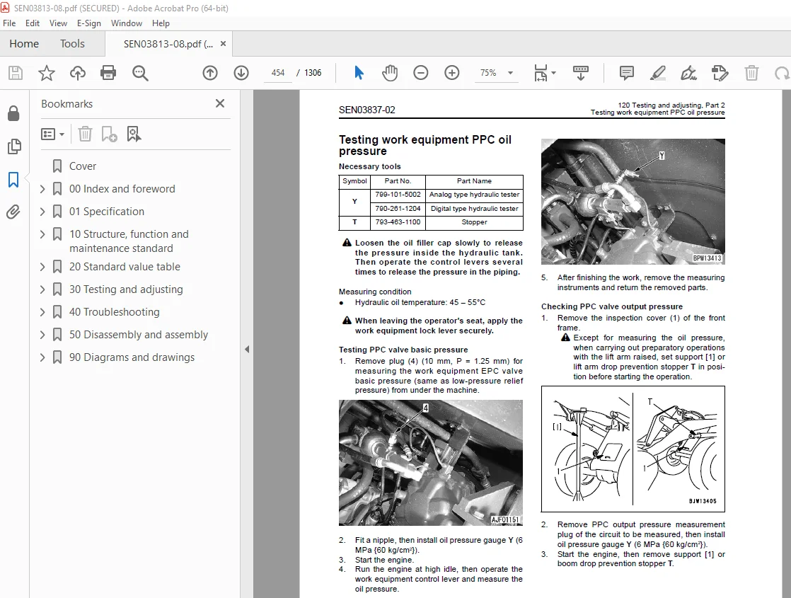
Testing work equipment PPC oil pressure 454
Bleeding air from hydraulic circuit 456
Releasing remaining pressure in hydraulic circuit 457
Testing and adjusting bucket positioner 458
Testing and adjusting of boom kick-out switch 459
Checking proximity switch operation pilot lamp 460
Procedure for testing diodes 461
Preparation work for troubleshooting for electric system 463
Starting KOMTRAX terminal operations 467
Indicator lamps of KOMTRAX terminal 471
130 Testing and adjusting, Part 3 475
Adjusting machine monitor 476
Adjusting replaced, reassembled or added sensor, controller, etc with machine monitor 477
Special functions of machine monitor (EMMS) 479
Pm clinic inspection chart 533
40 Troubleshooting 537
100 Failure code table and fuse locations 537
Failure codes table 538
Fuse locations 544
200 General information on troubleshooting 549
Points to remember when troubleshooting 550
Sequence of events in troubleshooting 551
Testing before troubleshooting 552
Classification and procedures of troubleshooting 553
Information contained in troubleshooting table 556
Connection table for connector pin numbers 558
T- branch box and T- branch adapter table 594
310 Troubleshooting by failure code (Display of code), Part 1 599
Failure code [2G40GZ] Brake: Oil pressure reduction 600
Failure code [6091NX] HST filter: Clogging 602
Failure code [989FN1] Travel speed: Overrun alarm 604
Failure code [AB00L6] Alternator R system: Hot short 606
Failure code [AB00MA] Alternator R system: Ground fault/Disconnection charge/Low charge voltage 608
Failure code [B@BAZG] Engine: Oil pressure reduction 610
Failure code [B@BCNS] Engine: Overheat 611
Failure code [B@BCZK] Engine: Low coolant level 612
Failure code [B@C6NS] Front brake: High oil temperature 614
Failure code [B@CRNS] HST: High oil temperature 615
320 Troubleshooting by failure code (Display of code), Part 2 617
Failure code [CA111] Abnormality in engine controller 619
Failure code [CA115] Engine Ne or Bkup speed sensor error 620
Failure code [CA122] Charge pressure sensor high error 622
Failure code [CA123] Charge pressure sensor low error 624
Failure code [CA131] Throttle sensor high error 626
Failure code [CA132] Throttle sensor low error 628
Failure code [CA144] Coolant sensor high error 630
Failure code [CA145] Coolant sensor low error 632
Failure code [CA153] Charge temperature sensor high error 634
Failure code [CA154] Charge temperature sensor low error 636
Failure code [CA155] Derating of speed by abnormally high charge temperature 638
Failure code [CA187] Sensor power supply 2 low error 640
Failure code [CA221] Atmospheric pressure sensor high error 642
Failure code [CA222] Atmospheric sensor low error 644
Failure code [CA227] Sensor power supply 2 high error 646
Failure code [CA234] Engine overspeed 647
Failure code [CA238] Ne speed sensor power supply error 648
Failure code [CA271] IMV (IMA) Short circuit 649
Failure code [CA272] IMV (IMA) Disconnection 650
Failure code [CA322] Injector #1 open/short error 652
Failure code [CA323] Injector #5 open/short error 654
Failure code [CA324] Injector #3 open/short error 656
Failure code [CA325] Injector #6 open/short error 658
Failure code [CA331] Injector #2 open/short error 660
Failure code [CA332] Injector #4 open/short error 662
Failure code [CA342] Calibration code inconsistency 664
Failure code [CA351] Injectors drive circuit error 666
Failure code [CA352] Sensor power supply 1 low error 668
Failure code [CA386] Sensor power supply 1 high error 670
330 Troubleshooting by failure code (Display of code), Part 3 673
Failure code [CA428] Abnormally high level in water sensor 676
Failure code [CA429] Abnormally low level in water sensor 678
Failure code [CA431] Idle validation switch error 680
Failure code [CA432] Idle validation action error 684
Failure code [CA435] Engine oil pressure switch error 688
Failure code [CA441] Battery voltage low error 689
Failure code [CA442] Battery voltage high error 692
Failure code [CA449] Common rail pressure high error 2 694
Failure code [CA451] Common rail pressure sensor high error 696
Failure code [CA452] Common rail pressure sensor low error 698
Failure code [CA488] Derating of torque by abnormally high charge temperature 700
Failure code [CA553] Common rail pressure high error 1 701
Failure code [CA559] Supply pump pressure very low error 702
Failure code [CA689] Engine Ne speed sensor error 704
Failure code [CA731] Engine Bkup speed sensor phase error 706
Failure code [CA757] All continuous data lost error 707
Failure code [CA778] Engine Bkup speed sensor error 710
Failure code [CA1633] KOMNET datalink timeout error 712
Failure code [CA2185] Throttle sensor supply voltage high error 716
Failure code [CA2186] Throttle sensor power supply low error 718
Failure code [CA2249] Supply pump pressure very low error 2 720
Failure code [CA2311] Abnormality in IMV (IMA) solenoid 722
Failure code [CA2555] Intake heater relay disconnection error 724
Failure code [CA2556] Intake heater relay short circuit error 726
340 Troubleshooting by failure code (Display of code), Part 4 729
Failure code [D160KY] Backup alarm/lamp relay 1 circuit: Hot short 730
Failure code [D192KY] ECSS solenoid relay: Hot short 732
Failure code [D1B0KA] HST safety relay: Disconnection 734
Failure code [D1B0KB] HST safety relay: Ground fault 736
Failure code [D1B0KY] HST safety relay: Hot short 738
Failure code [D5ZHL6] IGN C system: Ground fault/Disconnection 740
Failure code [DAF3KK] UNSW power supply: Ground fault/Disconnection 742
Failure code [DAFRKR] Machine monitor CAN-NET Signal: Disconnection 744
Failure code [DAJ0KK] HST controller power supply: Low voltage 748
Failure code [DAJ0KT] HST controller memory (EEPROM): Abnormality 750
Failure code [DAJ1L4] HST controller main power line: Disconnection/Ground fault 752
Failure code [DAJ1L6] HST controller main power line: Hot short 754
Failure code [DAJ2KK] Controller solenoid power supply: Low voltage 756
Failure code [DAJ2L3] HST controller load power supply holding line: Hot short in wiring harness 758
Failure code [DAJ2L4] HST controller load power supply holding line: Disconnection/Ground fault 760
Failure code [DAJ5KX] Sensor 5V power supply: Out of output range 762
Failure code [DAJ9KQ] HST controller model selection: Disagreement of model selection signals 764
Failure code [DAJRKR] HST controller CAN-NET signal: Disconnection 765
Failure code [DAJRMA] HST controller: Disagreement in option selection 771
350 Troubleshooting by failure code (Display of code), Part 5 773
Failure code [DB2RKR] Engine controller CAN-NET: Disconnection in signal line 775
Failure code [DD1NL4] Fan automatic reverse switch signal: Abnormality 780
Failure code [DD1NLD] Fan reverse switch signal: Abnormality 782
Failure code [DDB6KA] Parking brake switch A: Disconnection/Hot short 784
Failure code [DDB6KB] Parking brake switch B: Ground fault 786
Failure code [DDB6KZ] Parking brake switch (bottom switch) or parking brake reminder switch (intermediate switch): Trouble 788
Failure code [DDB6L0] Parking brake switch A: Ground fault 790
Failure code [DDB6L4] Parking brake switch B: Disconnection/Hot short 792
Failure code [DDD7KX] Travel speed control dial signal: Disconnection/Ground fault 794
Failure code [DDD7KY] Travel speed control dial signal: Hot short 796
Failure code [DDE5MA] Emergency steering operation switch: Disconnection 798
Failure code [DDK3KA] Directional selector switch: Disconnection/Hot short 800
Failure code [DDK3KB] Directional selector switch: Ground fault 802
Failure code [DDK6KA] FNR lever: Disconnection/Ground fault 804
Failure code [DDK6KY] FNR lever: Hot short 808
Failure code [DDS5L6] Steering: Low oil pressure (Operation of emergency steering) 810
360 Troubleshooting by failure code (Display of code), Part 6 813
Failure code [DF10KA] Travel speed range selector switch: Disconnection/Ground fault 815
Failure code [DF10KB] Travel speed range selector switch: Hot short 818
Failure code [DGH1KX] HST oil temperature sensor: Ground fault 820
Failure code [DGR2KB] Brake oil temperature sensor: Ground fault 821
Failure code [DGR2KZ] Brake oil temperature sensor: Disconnection/Hot short 822
Failure code [DHH1KX] HST oil pressure sensor: Disconnection/Ground fault 824
Failure code [DHH1KY] HST oil pressure sensor: Hot short 826
Failure code [DHTCL6] HST filter clogging sensor: Functional defect 828
Failure code [DJF1KA] Fuel level sensor: Disconnection/Hot short 830
Failure code [DLT3KX] Travel speed sensor B: Abnormality 832
Failure code [DLT4KX] Travel speed sensor A: Abnormality 836
Failure code [DLT4LC] Travel speed sensor A & B: Abnormality 838
Failure code [DV00KY] Alarm buzzer: Hot short 840
Failure code [DW26KA] Motor 2 solenoid: Disconnection/Ground fault 842
Failure code [DW26KY] Motor 2 solenoid: Hot short 844
Failure code [DW7BKY] Fan reverse solenoid circuit: Hot short 846
Failure code [DW7BKZ] Fan reverse solenoid circuit: Disconnection/Ground fault 848
370 Troubleshooting by failure code (Display of code), Part 7 851
Failure code [DX16KA] Fan EPC solenoid: Disconnection 852
Failure code [DX16KB] Fan EPC solenoid: Ground fault 853
Failure code [DX16KY] Fan EPC solenoid: Hot short 854
Failure code [DX19KA] Motor 1 solenoid: Disconnection 856
Failure code [DX19KB] Motor 1 solenoid: Ground fault 858
Failure code [DX19KY] Motor 1 solenoid: Hot short 860
Failure code [DX20KA] Clutch EPC solenoid: Disconnection 862
Failure code [DX20KB] Clutch EPC solenoid: Ground fault 864
Failure code [DX20KY] Clutch EPC solenoid: Hot short 866
Failure code [DXH7KB] Reverse solenoid: Ground fault 868
Failure code [DXH7KZ] Reverse solenoid: Disconnection/Hot short 870
Failure code [DXH8KB] Forward solenoid: Ground fault 872
Failure code [DXH8KZ] Forward solenoid: Disconnection/Hot short 874
Failure code [J141N1] Steering pump: Overrun alarm 876
Failure code [M100N1] HST pump: Overrun alarm 876
Failure code [M400N1] Motor 1: Overrun alarm 877
400 Troubleshooting of electrical system (E-mode) 879
E-1 Engine does not start 881
E-2 Preheater does not operate normally 888
E-3 Defective boom kick-out function and cancellation 892
E-4 Defective bucket positioner function and cancellation 896
E-5 Defective lift arm FLOATING holding function and cancellation 900
E-6 Travel direction selection system does not function 904
E-7 Wiper does not operate 908
E-8 Windshield washer does not operate 912
E-9 Headlamp, clearance lamp and tail lamp do not light up or go off 916
E-10 Working lamp does not light up or go off 924
E-11 Turn signal lamp and hazard lamp do not light up or go off 929
E-12 Brake lamp does not light or it keeps lighting up 936
E-13 Backup lamp does not light or it keeps lighting up 938
E-14 Backup alarm does not sound or it keeps sounding 941
E-15 Horn does not sound or it keeps sounding 944
E-16 Alarm buzzer does not sound or it keeps sounding 946
E-17 Air conditioner does not operate or stop 948
E-18 The KOMTRAX system does not work properly 951
500 Troubleshooting of hydraulic and mechanical system (H-mode) 955
Method of using troubleshooting chart 957
Failure code and cause table 960
H-1 The machine does not start 962
H-2 The travel speed is slow 963
H-3 The traction force is weak 964
H-4 Engine stalls when traveling or engine speed drops excessively 965
H-5 The gear is not shifted 966
H-6 The steering wheel does not turn 967
H-7 The steering wheel is heavy 968
H-8 Steering wheel shakes or jerks 969
H-9 Machine deviates naturally to one side when traveling 969
H-10 The brake does not work or does not work well 970
H-11 The brake is not released or is dragged 971
H-12 The lift arm does not rise or lower 972
H-13 The lift arm moves slowly or the lift arm rising force is insufficient 973
H-14 When rising, the lift arm comes to move slowly at specific height 974
H-15 The lift arm cylinder cannot hold down the bucket (The bucket 974
H-16 Hydraulic drifts of the lift arm occur often 974
H-17 The lift arm wobbles during operation 974
H-18 When the control lever is switched from “HOLD” to “RAISE,” the lift arm falls temporarily 975
H-19 The bucket does not tilt back 976
H-20 The bucket moves slowly or the tilting-back force is insufficient 977
H-21 The bucket comes to operate slowly in the midst of tilting-back 978
H-22 The bucket cylinder cannot hold down the bucket 978
H-23 Hydraulic drifts of the bucket occur often 978
H-24 The bucket wobbles during travel with load (The work equipment valve is set to “HOLD”) 978
H-25 When the control lever is switched from “HOLD” to “TILT,” the bucket falls temporarily 979
H-26 The control levers of the lift arm and bucket do not move smoothly and heavy 979
H-27 The ECSS does not operate and machine pitches and bounces 980
H-28 Fan revolution is abnormal (Fan sound/vibration is abnormally large or engine overheats) 981
600 Troubleshooting of engine (S-mode) 983
Method of using troubleshooting charts 984
S-1 Starting performance is poor 988
S-2 Engine does not start 989
S-3 Engine does not pick up smoothly 992
S-4 Engine stops during operations 993
S-5 Engine does not rotate smoothly 994
S-6 Engine lacks output (or lacks power) 995
S-7 Exhaust smoke is black (incomplete combustion) 996
S-8 Oil consumption is excessive (or exhaust smoke is blue) 997
S-9 Oil becomes contaminated quickly 998
S-10 Fuel consumption is excessive 999
S-11 Oil is in coolant (or coolant spurts back or coolant level goes down) 1000
S-12 Oil pressure drops 1001
S-13 Oil level rises (Entry of coolant or fuel) 1002
S-14 Coolant temperature becomes too high (overheating) 1003
S-15 Abnormal noise is made 1004
S-16 Vibration is excessive 1005
50 Disassembly and assembly 1007
100 General information on disassembly and assembly 1007
How to read this manual 1008
Coating materials list 1010
Special tool list 1013
Sketches of special tools 1017
200 Engine and cooling system 1027
Removal and installation of fuel supply pump assembly 1028
Removal and installation of fuel injector assembly 1030
Removal and installation of cylinder head assembly 1037
Removal and installation of engine hood assembly 1050
Removal and installation of radiator 1053
Removal and installation of air aftercooler 1056
Removal and installation of hydraulic oil cooler assembly 1058
Removal and installation of engine assembly 1060
Removal and installation of engine front oil seal assembly 1066
Removal and installation of engine rear oil seal assembly 1069
Removal and installation of cooling fan and fan motor assembly 1072
Removal and installation of fuel tank assembly 1075
310 Power train, Part 1 1079
Removal and installation of transfer assembly 1080
Disassembly and assembly of transfer assembly 1084
Removal and installation of parking brake assembly 1104
Disassembly and assembly of parking brake assembly 1106
320 Power train, Part 2 1113
Removal and installation of front axle assembly 1114
Removal and installation of rear axle assembly 1116
Disassembly and assembly of axle housing assembly 1119
Disassembly and assembly of differential assembly 1128
400 Undercarriage and frame 1157
Removal and installation of center hinge pin 1158
Removal and installation of counterweight 1168
500 Hydraulic system 1171
Removal and installation of HST pump and 4-gear pump assembly 1172
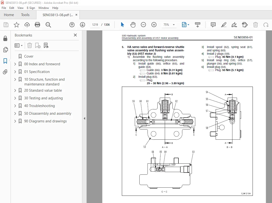
Disassembly and assembly of HST pump assembly 1176
Removal and installation of HST motor 1 assembly 1203
Removal and installation of HST motor 2 assembly 1205
Disassembly and assembly of HST motor assembly 1207
Removal and installation of work equipment control valve assembly 1223
Removal and installation of hydraulic tank 1225
Disassembly and assembly of hydraulic cylinder assembly 1227
600 Work equipment 1235
Removal and installation of work equipment assembly 1236
700 Cab and its attachments 1245
Removal and installation ofoperator’s cab and floor frame assembly 1246
Removal and installation of operator’s cab glass (Stuck glass) 1251
Removal and installation of air conditioner unit 1259
800 Electrical system 1267
Removal and installation of monitor panel 1268
Removal and installation of engine controller assembly 1270
Removal and installation of HST controller assembly 1271
Removal and installation of KOMTRAX terminal assembly 1272
90 Diagrams and drawings 1275
100 Hydraulic diagrams and drawings 1275
Hydraulic circuit diagram 1277
200 Electrical diagrams and drawings 1283
Electrical circuit diagram 1285
Connector list and stereogram 1303
00 Index and foreword 3
100 Index 3
Composition of shop manual 4
Table of contents 6
200 Foreword and general information 17
Safety notice 18
How to read the shop manual 23
Explanation of terms for maintenance standard 25
Handling of electric equipment and hydraulic component 27
Handling of connectors newly used for engines 36
How to read electric wire code 39
Precautions when carrying out operation 42
Method of disassembling and connecting push-pull type coupler 45
Standard tightening torque table 48
Conversion table 52
01 Specification 59
100 Specification and technical data 59
Specification dimension drawing 61
Specifications 62
Weight table 66
Table of fuel, coolant and lubricants 68
10 Structure, function and maintenance standard 71
100 Engine and cooling system 71
Engine mount and transfer mount 72
Damper 73
Cooling system 74
Cooling system hydraulic piping diagram 75
Cooling fan motor 77
200 Power train 87
Power train 89
Power train system diagram 90
Drive shaft 92
HST hydraulic piping diagram 93
HST pump 94
HST motor 102
Transfer 108
Clutch solenoid valve 119
Axle 120
Differential 122
Torque proportioning differential 127
Limited slip differential 130
Final drive 134
300 Steering system 141
Steering piping diagram 143
Steering column 144
Priority valve 145
Orbit-roll valve 148
2-way restrictor valve 156
Cushion valve 157
Steering cylinder 158
Emergency steering piping diagram 160
Emergency steering valve 161
Steering relief valve 164
400 Brake system 167
Brake piping diagram 169
Charge valve 170
Brake valve 174
Inching valve 178
Accumulator (for brake) 179
Slack adjuster 180
Brake 182
Parking brake control 187
Parking brake 188
500 Undercarriage and frame 191
Axle mount and center hinge pin 192
Tires 197
600 Hydraulic system 199
Work equipment hydraulic piping diagram 200
Work equipment control lever linkage 204
Hydraulic tank 208
4-gear pump 210
Work equipment control valve 212
PPC valve 237
Lock valve 252
Accumulator (for PPC circuit) 253
Bypass valve 254
Quick coupler solenoid valve 257
ECSS valve 258
Accumulator (for ECSS) 260
700 Work equipment 263
Work equipment linkage 264
Bucket 268
Bucket positioner and boom kick-out 272
Work equipment cylinder 285
800 Cab and its attachments 289
Cab 291
Air conditioner 292
910 Electrical system, Part 1 305
Machine monitor system 306
Machine monitor 310
920 Electrical system, Part 2 333
Electrical system (HST controller system) 334
HST controller 350
ECSS system 352
KOMTRAX system 354
Engine starting circuit 356
Engine stopping circuit 358
Preheating circuit 359
Engine output derating function 360
Automatic warm-up function 360
Parking brake circuit 361
Coupler plunger control system 364
Multi-function knob 365
Max traction switch 366
Sensor 367
20 Standard value table 375
100 Standard service value table 375
Standard service value table 376
Standard service value table for chassis 377
30 Testing and adjusting 385
110 Testing and adjusting, Part 1 385
Tools for testing, adjusting, and troubleshooting 388
Sketches of special tools 393
Measuring engine speed 394
Measuring exhaust gas color 396
Adjusting valve clearance 398
Measuring compression pressure 400
Measuring blow-by pressure 403
Measuring engine oil pressure 404
Measuring intake air (boost) pressure 405
Handling fuel system equipment 407
Releasing residual pressure in fuel system 407
Measuring fuel pressure 408
Measuring fuel return rate and leakage 410
Bleeding air from fuel circuit 414
Testing leakage in fuel system 415
Handling reduced cylinder mode operation 416
Handling no-injection cranking operation 416
Handling controller voltage circuit 417
Check of muffler and muffler stack for looseness and damage 417
Check of muffler function 418
Check of installed condition of cylinder head and manifolds 418
Check of engine piping for damage and looseness 419
Testing and adjusting air conditioner compressor belt tension 419
Replacing alternator belt 420
120 Testing and adjusting, Part 2 423
Checking operating force of accelerator pedal 425
Checking directional lever 426
Testing and adjusting HST oil pressure 427
Testing clutch control pressure 431
Testing and adjusting steering wheel 432
Testing and adjusting steering oil pressure 434
Bleeding air from steering circuit 436
Testing hydraulic fan 437
Measuring brake pedal 439
Testing and adjusting brake pedal linkage 440
Measuring brake performance 441
Testing and adjusting accumulator charge pressure 442
Testing wheel brake oil pressure 444
Testing wear of brake disc 447
Bleeding air from wheel brake circuit 448
Releasing residual pressure in brake accumulator circuit 449
Testing parking brake performance 450
Testing and adjusting parking brake control cable 451
Measuring and adjusting work equipment control lever 452
Testing and adjusting work equipment hydraulic pressure 453
Testing work equipment PPC oil pressure 454
Bleeding air from hydraulic circuit 456
Releasing remaining pressure in hydraulic circuit 457
Testing and adjusting bucket positioner 458
Testing and adjusting of boom kick-out switch 459
Checking proximity switch operation pilot lamp 460
Procedure for testing diodes 461
Preparation work for troubleshooting for electric system 463
Starting KOMTRAX terminal operations 467
Indicator lamps of KOMTRAX terminal 471
130 Testing and adjusting, Part 3 475
Adjusting machine monitor 476
Adjusting replaced, reassembled or added sensor, controller, etc with machine monitor 477
Special functions of machine monitor (EMMS) 479
Pm clinic inspection chart 533
40 Troubleshooting 537
100 Failure code table and fuse locations 537
Failure codes table 538
Fuse locations 544
200 General information on troubleshooting 549
Points to remember when troubleshooting 550
Sequence of events in troubleshooting 551
Testing before troubleshooting 552
Classification and procedures of troubleshooting 553
Information contained in troubleshooting table 556
Connection table for connector pin numbers 558
T- branch box and T- branch adapter table 594
310 Troubleshooting by failure code (Display of code), Part 1 599
Failure code [2G40GZ] Brake: Oil pressure reduction 600
Failure code [6091NX] HST filter: Clogging 602
Failure code [989FN1] Travel speed: Overrun alarm 604
Failure code [AB00L6] Alternator R system: Hot short 606
Failure code [AB00MA] Alternator R system: Ground fault/Disconnection charge/Low charge voltage 608
Failure code [B@BAZG] Engine: Oil pressure reduction 610
Failure code [B@BCNS] Engine: Overheat 611
Failure code [B@BCZK] Engine: Low coolant level 612
Failure code [B@C6NS] Front brake: High oil temperature 614
Failure code [B@CRNS] HST: High oil temperature 615
320 Troubleshooting by failure code (Display of code), Part 2 617
Failure code [CA111] Abnormality in engine controller 619
Failure code [CA115] Engine Ne or Bkup speed sensor error 620
Failure code [CA122] Charge pressure sensor high error 622
Failure code [CA123] Charge pressure sensor low error 624
Failure code [CA131] Throttle sensor high error 626
Failure code [CA132] Throttle sensor low error 628
Failure code [CA144] Coolant sensor high error 630
Failure code [CA145] Coolant sensor low error 632
Failure code [CA153] Charge temperature sensor high error 634
Failure code [CA154] Charge temperature sensor low error 636
Failure code [CA155] Derating of speed by abnormally high charge temperature 638
Failure code [CA187] Sensor power supply 2 low error 640
Failure code [CA221] Atmospheric pressure sensor high error 642
Failure code [CA222] Atmospheric sensor low error 644
Failure code [CA227] Sensor power supply 2 high error 646
Failure code [CA234] Engine overspeed 647
Failure code [CA238] Ne speed sensor power supply error 648
Failure code [CA271] IMV (IMA) Short circuit 649
Failure code [CA272] IMV (IMA) Disconnection 650
Failure code [CA322] Injector #1 open/short error 652
Failure code [CA323] Injector #5 open/short error 654
Failure code [CA324] Injector #3 open/short error 656
Failure code [CA325] Injector #6 open/short error 658
Failure code [CA331] Injector #2 open/short error 660
Failure code [CA332] Injector #4 open/short error 662
Failure code [CA342] Calibration code inconsistency 664
Failure code [CA351] Injectors drive circuit error 666
Failure code [CA352] Sensor power supply 1 low error 668
Failure code [CA386] Sensor power supply 1 high error 670
330 Troubleshooting by failure code (Display of code), Part 3 673
Failure code [CA428] Abnormally high level in water sensor 676
Failure code [CA429] Abnormally low level in water sensor 678
Failure code [CA431] Idle validation switch error 680
Failure code [CA432] Idle validation action error 684
Failure code [CA435] Engine oil pressure switch error 688
Failure code [CA441] Battery voltage low error 689
Failure code [CA442] Battery voltage high error 692
Failure code [CA449] Common rail pressure high error 2 694
Failure code [CA451] Common rail pressure sensor high error 696
Failure code [CA452] Common rail pressure sensor low error 698
Failure code [CA488] Derating of torque by abnormally high charge temperature 700
Failure code [CA553] Common rail pressure high error 1 701
Failure code [CA559] Supply pump pressure very low error 702
Failure code [CA689] Engine Ne speed sensor error 704
Failure code [CA731] Engine Bkup speed sensor phase error 706
Failure code [CA757] All continuous data lost error 707
Failure code [CA778] Engine Bkup speed sensor error 710
Failure code [CA1633] KOMNET datalink timeout error 712
Failure code [CA2185] Throttle sensor supply voltage high error 716
Failure code [CA2186] Throttle sensor power supply low error 718
Failure code [CA2249] Supply pump pressure very low error 2 720
Failure code [CA2311] Abnormality in IMV (IMA) solenoid 722
Failure code [CA2555] Intake heater relay disconnection error 724
Failure code [CA2556] Intake heater relay short circuit error 726
340 Troubleshooting by failure code (Display of code), Part 4 729
Failure code [D160KY] Backup alarm/lamp relay 1 circuit: Hot short 730
Failure code [D192KY] ECSS solenoid relay: Hot short 732
Failure code [D1B0KA] HST safety relay: Disconnection 734
Failure code [D1B0KB] HST safety relay: Ground fault 736
Failure code [D1B0KY] HST safety relay: Hot short 738
Failure code [D5ZHL6] IGN C system: Ground fault/Disconnection 740
Failure code [DAF3KK] UNSW power supply: Ground fault/Disconnection 742
Failure code [DAFRKR] Machine monitor CAN-NET Signal: Disconnection 744
Failure code [DAJ0KK] HST controller power supply: Low voltage 748
Failure code [DAJ0KT] HST controller memory (EEPROM): Abnormality 750
Failure code [DAJ1L4] HST controller main power line: Disconnection/Ground fault 752
Failure code [DAJ1L6] HST controller main power line: Hot short 754
Failure code [DAJ2KK] Controller solenoid power supply: Low voltage 756
Failure code [DAJ2L3] HST controller load power supply holding line: Hot short in wiring harness 758
Failure code [DAJ2L4] HST controller load power supply holding line: Disconnection/Ground fault 760
Failure code [DAJ5KX] Sensor 5V power supply: Out of output range 762
Failure code [DAJ9KQ] HST controller model selection: Disagreement of model selection signals 764
Failure code [DAJRKR] HST controller CAN-NET signal: Disconnection 765
Failure code [DAJRMA] HST controller: Disagreement in option selection 771
350 Troubleshooting by failure code (Display of code), Part 5 773
Failure code [DB2RKR] Engine controller CAN-NET: Disconnection in signal line 775
Failure code [DD1NL4] Fan automatic reverse switch signal: Abnormality 780
Failure code [DD1NLD] Fan reverse switch signal: Abnormality 782
Failure code [DDB6KA] Parking brake switch A: Disconnection/Hot short 784
Failure code [DDB6KB] Parking brake switch B: Ground fault 786
Failure code [DDB6KZ] Parking brake switch (bottom switch) or parking brake reminder switch (intermediate switch): Trouble 788
Failure code [DDB6L0] Parking brake switch A: Ground fault 790
Failure code [DDB6L4] Parking brake switch B: Disconnection/Hot short 792
Failure code [DDD7KX] Travel speed control dial signal: Disconnection/Ground fault 794
Failure code [DDD7KY] Travel speed control dial signal: Hot short 796
Failure code [DDE5MA] Emergency steering operation switch: Disconnection 798
Failure code [DDK3KA] Directional selector switch: Disconnection/Hot short 800
Failure code [DDK3KB] Directional selector switch: Ground fault 802
Failure code [DDK6KA] FNR lever: Disconnection/Ground fault 804
Failure code [DDK6KY] FNR lever: Hot short 808
Failure code [DDS5L6] Steering: Low oil pressure (Operation of emergency steering) 810
360 Troubleshooting by failure code (Display of code), Part 6 813
Failure code [DF10KA] Travel speed range selector switch: Disconnection/Ground fault 815
Failure code [DF10KB] Travel speed range selector switch: Hot short 818
Failure code [DGH1KX] HST oil temperature sensor: Ground fault 820
Failure code [DGR2KB] Brake oil temperature sensor: Ground fault 821
Failure code [DGR2KZ] Brake oil temperature sensor: Disconnection/Hot short 822
Failure code [DHH1KX] HST oil pressure sensor: Disconnection/Ground fault 824
Failure code [DHH1KY] HST oil pressure sensor: Hot short 826
Failure code [DHTCL6] HST filter clogging sensor: Functional defect 828
Failure code [DJF1KA] Fuel level sensor: Disconnection/Hot short 830
Failure code [DLT3KX] Travel speed sensor B: Abnormality 832
Failure code [DLT4KX] Travel speed sensor A: Abnormality 836
Failure code [DLT4LC] Travel speed sensor A & B: Abnormality 838
Failure code [DV00KY] Alarm buzzer: Hot short 840
Failure code [DW26KA] Motor 2 solenoid: Disconnection/Ground fault 842
Failure code [DW26KY] Motor 2 solenoid: Hot short 844
Failure code [DW7BKY] Fan reverse solenoid circuit: Hot short 846
Failure code [DW7BKZ] Fan reverse solenoid circuit: Disconnection/Ground fault 848
370 Troubleshooting by failure code (Display of code), Part 7 851
Failure code [DX16KA] Fan EPC solenoid: Disconnection 852
Failure code [DX16KB] Fan EPC solenoid: Ground fault 853
Failure code [DX16KY] Fan EPC solenoid: Hot short 854
Failure code [DX19KA] Motor 1 solenoid: Disconnection 856
Failure code [DX19KB] Motor 1 solenoid: Ground fault 858
Failure code [DX19KY] Motor 1 solenoid: Hot short 860
Failure code [DX20KA] Clutch EPC solenoid: Disconnection 862
Failure code [DX20KB] Clutch EPC solenoid: Ground fault 864
Failure code [DX20KY] Clutch EPC solenoid: Hot short 866
Failure code [DXH7KB] Reverse solenoid: Ground fault 868
Failure code [DXH7KZ] Reverse solenoid: Disconnection/Hot short 870
Failure code [DXH8KB] Forward solenoid: Ground fault 872
Failure code [DXH8KZ] Forward solenoid: Disconnection/Hot short 874
Failure code [J141N1] Steering pump: Overrun alarm 876
Failure code [M100N1] HST pump: Overrun alarm 876
Failure code [M400N1] Motor 1: Overrun alarm 877
400 Troubleshooting of electrical system (E-mode) 879
E-1 Engine does not start 881
E-2 Preheater does not operate normally 888
E-3 Defective boom kick-out function and cancellation 892
E-4 Defective bucket positioner function and cancellation 896
E-5 Defective lift arm FLOATING holding function and cancellation 900
E-6 Travel direction selection system does not function 904
E-7 Wiper does not operate 908
E-8 Windshield washer does not operate 912
E-9 Headlamp, clearance lamp and tail lamp do not light up or go off 916
E-10 Working lamp does not light up or go off 924
E-11 Turn signal lamp and hazard lamp do not light up or go off 929
E-12 Brake lamp does not light or it keeps lighting up 936
E-13 Backup lamp does not light or it keeps lighting up 938
E-14 Backup alarm does not sound or it keeps sounding 941
E-15 Horn does not sound or it keeps sounding 944
E-16 Alarm buzzer does not sound or it keeps sounding 946
E-17 Air conditioner does not operate or stop 948
E-18 The KOMTRAX system does not work properly 951
500 Troubleshooting of hydraulic and mechanical system (H-mode) 955
Method of using troubleshooting chart 957
Failure code and cause table 960
H-1 The machine does not start 962
H-2 The travel speed is slow 963
H-3 The traction force is weak 964
H-4 Engine stalls when traveling or engine speed drops excessively 965
H-5 The gear is not shifted 966
H-6 The steering wheel does not turn 967
H-7 The steering wheel is heavy 968
H-8 Steering wheel shakes or jerks 969
H-9 Machine deviates naturally to one side when traveling 969
H-10 The brake does not work or does not work well 970
H-11 The brake is not released or is dragged 971
H-12 The lift arm does not rise or lower 972
H-13 The lift arm moves slowly or the lift arm rising force is insufficient 973
H-14 When rising, the lift arm comes to move slowly at specific height 974
H-15 The lift arm cylinder cannot hold down the bucket (The bucket 974
H-16 Hydraulic drifts of the lift arm occur often 974
H-17 The lift arm wobbles during operation 974
H-18 When the control lever is switched from “HOLD” to “RAISE,” the lift arm falls temporarily 975
H-19 The bucket does not tilt back 976
H-20 The bucket moves slowly or the tilting-back force is insufficient 977
H-21 The bucket comes to operate slowly in the midst of tilting-back 978
H-22 The bucket cylinder cannot hold down the bucket 978
H-23 Hydraulic drifts of the bucket occur often 978
H-24 The bucket wobbles during travel with load (The work equipment valve is set to “HOLD”) 978
H-25 When the control lever is switched from “HOLD” to “TILT,” the bucket falls temporarily 979
H-26 The control levers of the lift arm and bucket do not move smoothly and heavy 979
H-27 The ECSS does not operate and machine pitches and bounces 980
H-28 Fan revolution is abnormal (Fan sound/vibration is abnormally large or engine overheats) 981
600 Troubleshooting of engine (S-mode) 983
Method of using troubleshooting charts 984
S-1 Starting performance is poor 988
S-2 Engine does not start 989
S-3 Engine does not pick up smoothly 992
S-4 Engine stops during operations 993
S-5 Engine does not rotate smoothly 994
S-6 Engine lacks output (or lacks power) 995
S-7 Exhaust smoke is black (incomplete combustion) 996
S-8 Oil consumption is excessive (or exhaust smoke is blue) 997
S-9 Oil becomes contaminated quickly 998
S-10 Fuel consumption is excessive 999
S-11 Oil is in coolant (or coolant spurts back or coolant level goes down) 1000
S-12 Oil pressure drops 1001
S-13 Oil level rises (Entry of coolant or fuel) 1002
S-14 Coolant temperature becomes too high (overheating) 1003
S-15 Abnormal noise is made 1004
S-16 Vibration is excessive 1005
50 Disassembly and assembly 1007
100 General information on disassembly and assembly 1007
How to read this manual 1008
Coating materials list 1010
Special tool list 1013
Sketches of special tools 1017
200 Engine and cooling system 1027
Removal and installation of fuel supply pump assembly 1028
Removal and installation of fuel injector assembly 1030
Removal and installation of cylinder head assembly 1037
Removal and installation of engine hood assembly 1050
Removal and installation of radiator 1053
Removal and installation of air aftercooler 1056
Removal and installation of hydraulic oil cooler assembly 1058
Removal and installation of engine assembly 1060
Removal and installation of engine front oil seal assembly 1066
Removal and installation of engine rear oil seal assembly 1069
Removal and installation of cooling fan and fan motor assembly 1072
Removal and installation of fuel tank assembly 1075
310 Power train, Part 1 1079
Removal and installation of transfer assembly 1080
Disassembly and assembly of transfer assembly 1084
Removal and installation of parking brake assembly 1104
Disassembly and assembly of parking brake assembly 1106
320 Power train, Part 2 1113
Removal and installation of front axle assembly 1114
Removal and installation of rear axle assembly 1116
Disassembly and assembly of axle housing assembly 1119
Disassembly and assembly of differential assembly 1128
400 Undercarriage and frame 1157
Removal and installation of center hinge pin 1158
Removal and installation of counterweight 1168
500 Hydraulic system 1171
Removal and installation of HST pump and 4-gear pump assembly 1172
Disassembly and assembly of HST pump assembly 1176
Removal and installation of HST motor 1 assembly 1203
Removal and installation of HST motor 2 assembly 1205
Disassembly and assembly of HST motor assembly 1207
Removal and installation of work equipment control valve assembly 1223
Removal and installation of hydraulic tank 1225
Disassembly and assembly of hydraulic cylinder assembly 1227
600 Work equipment 1235
Removal and installation of work equipment assembly 1236
700 Cab and its attachments 1245
Removal and installation ofoperator’s cab and floor frame assembly 1246
Removal and installation of operator’s cab glass (Stuck glass) 1251
Removal and installation of air conditioner unit 1259
800 Electrical system 1267
Removal and installation of monitor panel 1268
Removal and installation of engine controller assembly 1270
Removal and installation of HST controller assembly 1271
Removal and installation of KOMTRAX terminal assembly 1272
90 Diagrams and drawings 1275
100 Hydraulic diagrams and drawings 1275
Hydraulic circuit diagram 1277
200 Electrical diagrams and drawings 1283
Electrical circuit diagram 1285
Connector list and stereogram 1303
DESCRIPTION:
Komatsu WA250-6 WA250PZ-6 Wheel Loader Shop Manual SEN03813-08 – PDF DOWNLOAD
SERIAL NUMBERS
WA250- 75001 and up
WA250PZ-75001 and up
WA250PZ-75001 and up
How to read the shop manual
1. Composition of shop manual
This shop manual contains the necessary technical information for services performed in a workshop.
For ease of understanding, the manual is divided into the following sections.
00. Index and foreword
This section explains the shop manuals list, table of contents, safety, and basic information.
01. Specification
This section explains the specifications of the machine.
10. Structure, function and maintenance standard
This section explains the structure, function, and maintenance standard values of each component.
The structure and function sub-section explains the structure and function of each component. It
serves not only to give an understanding of the structure, but also serves as reference material for
troubleshooting. The maintenance standard sub-section explains the criteria and remedies for disassembly
and service.
20. Standard value table
This section explains the standard values for new machine and judgement criteria for testing,
adjusting, and troubleshooting. This standard value table is used to check the standard values in
testing and adjusting and to judge parts in troubleshooting.
30. Testing and adjusting
This section explains measuring instruments and measuring methods for testing and adjusting, and
method of adjusting each part. The standard values and judgement criteria for testing and adjusting
are explained in Testing and adjusting.
40. Troubleshooting
This section explains how to find out failed parts and how to repair them. The troubleshooting is
divided by failure modes. The “S mode” of the troubleshooting related to the engine may be also
explained in the Chassis volume and Engine volume. In this case, see the Chassis volume.
50. Disassembly and assembly
This section explains the special tools and procedures for removing, installing, disassembling, and
assembling each component, as well as precautions for them. In addition, tightening torque and
quantity and weight of coating material, oil, grease, and coolant necessary for the work are also
explained.
90. Diagrams and drawings (chassis volume)/Repair and replacement of parts (engine volume)
q Chassis volume
This section gives hydraulic circuit diagrams and electrical circuit diagrams.
q Engine volume
This section explains the method of reproducing, repairing, and replacing parts.
S.V 29/12/24


