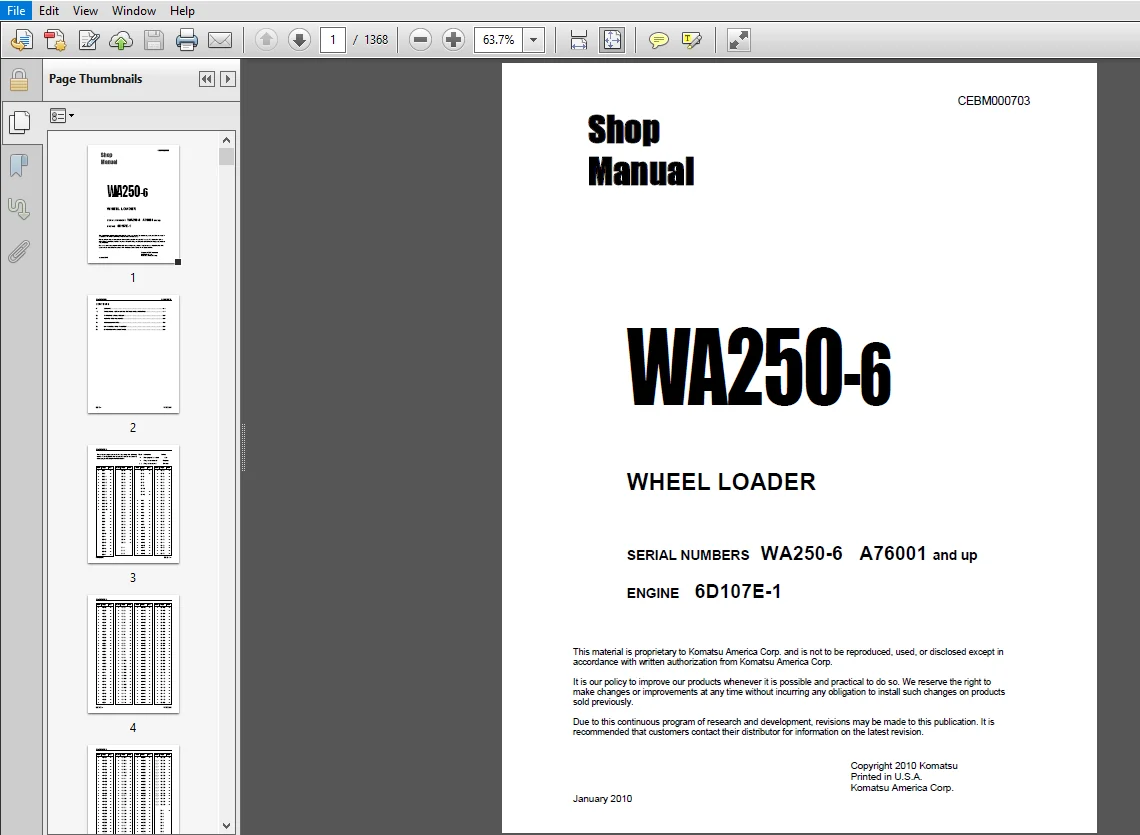
Komatsu WA250-6 Wheel Loader Shop Manual A76001 and up – PDF DOWNLOAD
Original price was: $37.95.$18.95Current price is: $18.95.
Komatsu WA250-6 Wheel Loader Shop Manual A76001 and up
SERIAL NUMBERS WA250-6 A76001 and up
Description
Komatsu WA250-6 Wheel Loader Shop Manual A76001 and up
FILE DETAILS:
Komatsu WA250-6 Wheel Loader Shop Manual A76001 and up
Brands: Komatsu
Equipment Type: Wheel Loader
Manuals Type: Shop Manual
Machine Model: WA250-6
Serial Number: A76001 and up
Book Code: CEBM000703
Language: English
Pages: 1368
File Format: Portable Document Format (PDF)
DESCRIPTION:
Komatsu WA250-6 Wheel Loader Shop Manual A76001 and up
GENERAL :
This shop manual has been prepared as an aid to improve the quality of repairs by giving the serviceman an accurate understanding of the product and by showing him the correct way to perform repairs and make judgments. Make sure you understand the contents of this manual and use it to full effect at every opportunity. This shop manual mainly contains the necessary technical information for operations performed in a service workshop. For ease of understanding, the manual is divided into the following sections. These sections are further divided into each main group of components.
General:
This section lists the general machine dimensions, performance specifications, component weights, and fuel, coolant, and lubricant specification charts. Structure, Function, and Maintenance Standard This section explains the structure and function of each component. It serves not only to give an understanding of the structure, but also serves as reference material for troubleshooting. In addition, this section gives the judgment standards when inspecting disassembled parts.
Standard Value Table
This section explains the standard values for a new machine and the judgment criteria for testing, adjusting, and troubleshooting. This standard value table is used to check the standard values in testing and adjusting and to judge parts in troubleshooting.
Testing and Adjusting
This section explains checks to be made before and after performing repairs, as well as adjustments to be made at completion of the checks and repairs.
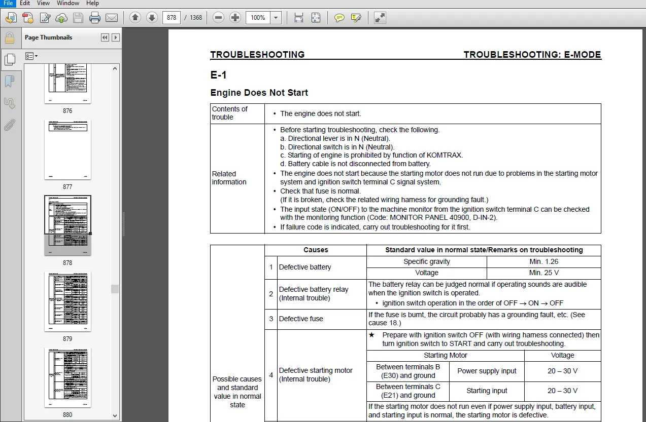
Troubleshooting
Troubleshooting charts correlating Problems to Causes are also included in this section.
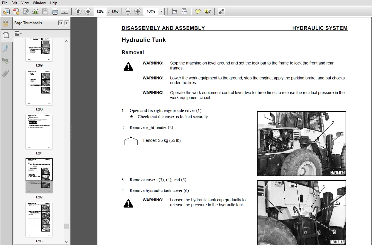
Disassembly and Assembly
This section explains the order to be followed when
removing, installing, disassembling, or assembling each
component, as well as precautions to be taken for these
operations.
Other
This section has the foldout drawings for the machine.
TABLE OF CONTENTS:
Komatsu WA250-6 Wheel Loader Shop Manual A76001 and up
COVER..........................................................................................................................................................   1
FOREWORD.......................................................................................................................................................   2
	CONTENTS...................................................................................................................................................   2
	REVISED PAGES..............................................................................................................................................   3
	SAFETY.....................................................................................................................................................  15
		Safety Notice..........................................................................................................................................  15
			Important Safety Notice............................................................................................................................  15
			General Precautions................................................................................................................................  15
			Preparations for Work..............................................................................................................................  16
			Precautions During Work............................................................................................................................  16
	GENERAL....................................................................................................................................................  17
	HOW TO READ THE SHOP MANUAL................................................................................................................................  18
		Volumes................................................................................................................................................  18
		Distribution and Updating..............................................................................................................................  18
		Filing Method..........................................................................................................................................  18
		Revised Edition Mark...................................................................................................................................  18
		Revisions..............................................................................................................................................  18
		Symbols................................................................................................................................................  18
	HOISTING INSTRUCTIONS......................................................................................................................................  19
		Hoisting...............................................................................................................................................  19
		Making Signs...........................................................................................................................................  19
		Precautions............................................................................................................................................  19
			Precautions for Sling Work.........................................................................................................................  19
			Precautions for Using Mobile Crane.................................................................................................................  20
			Precautions for Using Overhead Hoist Crane.........................................................................................................  20
		Selecting Wire Ropes...................................................................................................................................  21
	AIR CONDITIONER CIRCUITS...................................................................................................................................  22
		Precautions for Handling Hoses and Tubes...............................................................................................................  22
			Disconnecting Hoses and Tubes......................................................................................................................  22
			Connecting Hoses and Tubes.........................................................................................................................  22
	MAINTENANCE STANDARD TERMS.................................................................................................................................  23
	HANDLING ELECTRIC AND HYDRAULIC EQUIPMENT..................................................................................................................  25
		Handling Electric Equipment............................................................................................................................  25
			Handling Wiring Harnesses and Connectors...........................................................................................................  25
			Main Failures Occurring in Wiring Harness..........................................................................................................  25
			Removing, Installing, and Drying Connectors and Wiring Harnesses...................................................................................  26
			Handling Controller................................................................................................................................  30
			Troubleshooting Electric Circuits..................................................................................................................  30
		Handling Hydraulic Equipment...........................................................................................................................  31
		Handling Connectors Used for Engines...................................................................................................................  32
			Slide Lock Type....................................................................................................................................  32
			Pull Lock Type.....................................................................................................................................  33
			Push Lock Type.....................................................................................................................................  33
			Turn-housing Type (Round Green Connector)..........................................................................................................  35
	PRECAUTIONS FOR OPERATIONS.................................................................................................................................  36
		Precautions when Carrying Out Removal Work.............................................................................................................  36
		Precautions when Carrying Out Installation Work........................................................................................................  37
		Precautions when Completing the Operation..............................................................................................................  38
	PUSH-PULL COUPLER..........................................................................................................................................  39
		Type 1.................................................................................................................................................  39
			Disconnection......................................................................................................................................  39
			Connection.........................................................................................................................................  39
		Type 2.................................................................................................................................................  40
			Disconnection......................................................................................................................................  40
			Connection.........................................................................................................................................  40
		Type 3.................................................................................................................................................  41
			Disconnection......................................................................................................................................  41
			Connection.........................................................................................................................................  41
	COATING MATERIALS..........................................................................................................................................  42
	STANDARD TIGHTENING TORQUE.................................................................................................................................  44
		Standard Tightening Tables.............................................................................................................................  44
			For Bolts and Nuts.................................................................................................................................  44
			For Split Flange Bolts.............................................................................................................................  45
			For O-Ring Boss Piping Joints......................................................................................................................  45
			For O-Ring Boss Plugs..............................................................................................................................  46
			For Hoses (Taper-Seal Type and Face-Seal Type).....................................................................................................  46
			For Face Seal Joints...............................................................................................................................  47
			For 102, 107, and 114 Engine Series (Bolts and Nuts)...............................................................................................  47
			For 102, 107, and 114 Engine Series (Eye Joints)...................................................................................................  47
			For 102, 107, and 114 Engine Series (Taper Screws).................................................................................................  48
	CONVERSION TABLES..........................................................................................................................................  49
		Method of Using the Conversion Table...................................................................................................................  49
01 GENERAL.....................................................................................................................................................  55
	SPECIFICATIONS.............................................................................................................................................  56
		Dimension Drawing......................................................................................................................................  56
		Specification Tables...................................................................................................................................  58
	WEIGHT TABLE...............................................................................................................................................  62
	FUEL, COOLANT, AND LUBRICANTS..............................................................................................................................  64
10 STRUCTURE, FUNCTION AND MAINTENANCE STANDARD................................................................................................................  67
	ENGINE AND COOLING SYSTEM..................................................................................................................................  71
		Engine and Transmission Mounting.......................................................................................................................  71
			Torque Values......................................................................................................................................  71
		Damper.................................................................................................................................................  72
			Torque Values......................................................................................................................................  73
			Outline............................................................................................................................................  73
		Cooling System.........................................................................................................................................  74
			Specifications.....................................................................................................................................  74
		Cooling System Hydraulic Piping Diagram................................................................................................................  75
			Outline............................................................................................................................................  75
		Cooling Fan Motor......................................................................................................................................  76
			Type: LMF16........................................................................................................................................  76
			Torque Values......................................................................................................................................  77
			Specifications.....................................................................................................................................  77
			Torque Values......................................................................................................................................  79
			Hydraulic Motor....................................................................................................................................  80
				Function.......................................................................................................................................  80
				Principle of Operation.........................................................................................................................  80
			Suction Safety Valve...............................................................................................................................  81
				Suction Function...............................................................................................................................  81
				Operation......................................................................................................................................  81
				Safety Function................................................................................................................................  82
				Function.......................................................................................................................................  82
				Operation......................................................................................................................................  82
			Operation of Reversible Valve......................................................................................................................  83
			Flow Control Valve (Continuously Variable Type)....................................................................................................  84
				Function.......................................................................................................................................  84
				Operation......................................................................................................................................  84
	POWER TRAIN SYSTEM.........................................................................................................................................  85
		Drive Line Components..................................................................................................................................  85
		System Diagram.........................................................................................................................................  86
			Outline............................................................................................................................................  87
		Drive Shaft............................................................................................................................................  88
			Torque Values......................................................................................................................................  88
			Outline............................................................................................................................................  88
		HST Hydraulic Piping Diagram...........................................................................................................................  89
		HST Pump...............................................................................................................................................  90
			Specifications.....................................................................................................................................  91
			Operation..........................................................................................................................................  92
				Flow of Power..................................................................................................................................  92
				Flow of Oil....................................................................................................................................  92
			High-Pressure Relief Valve.........................................................................................................................  93
				Function.......................................................................................................................................  93
				Operation......................................................................................................................................  94
			Low-pressure Relief Valve..........................................................................................................................  95
				Function.......................................................................................................................................  95
				Operation......................................................................................................................................  95
			HST Charge Pump....................................................................................................................................  96
				Outline........................................................................................................................................  97
				Specifications.................................................................................................................................  97
				Function.......................................................................................................................................  97
			Speed-Related Valve (DA Valve).....................................................................................................................  98
				Function.......................................................................................................................................  98
				Operation......................................................................................................................................  98
			High-Pressure Cutoff Valve.........................................................................................................................  99
				Function.......................................................................................................................................  99
				Operation......................................................................................................................................  99
		HST Motor.............................................................................................................................................. 100
			HST Motor 1........................................................................................................................................ 100
				Specifications................................................................................................................................. 101
			HST Motor 2........................................................................................................................................ 102
				Specifications................................................................................................................................. 103
				Principle...................................................................................................................................... 104
				Structure...................................................................................................................................... 104
				Operation...................................................................................................................................... 104
			EP Servo Valve..................................................................................................................................... 105
				Function....................................................................................................................................... 105
				Operation...................................................................................................................................... 105
			HA Servo Valve..................................................................................................................................... 106
				Function....................................................................................................................................... 106
				Operation...................................................................................................................................... 106
			Directional Shuttle Valve.......................................................................................................................... 107
				Function....................................................................................................................................... 107
				Operation...................................................................................................................................... 107
		Transfer............................................................................................................................................... 108
			Torque Values...................................................................................................................................... 109
			Torque Values...................................................................................................................................... 111
			Input Shaft........................................................................................................................................ 112
			Output Shaft....................................................................................................................................... 114
				Torque Values.................................................................................................................................. 117
			Outline............................................................................................................................................ 118
				Relation between transfer clutch and transfer clutch pressure at respective speed ranges....................................................... 118
				Relationship between accelerator pedal angle and travel speed (A) for starting transfer clutch switching modulation............................ 118
			Operation of Clutch................................................................................................................................ 119
				Clutch is Engaged (fixed)...................................................................................................................... 119
				Clutch is Disengaged (released)................................................................................................................ 119
			Power Transmitting Route........................................................................................................................... 120
				Low-Speed Mode................................................................................................................................. 120
				High-Speed Mode................................................................................................................................ 121
			Clutch Solenoid Valve.............................................................................................................................. 122
				Operation...................................................................................................................................... 122
	DRIVE AXLE SYSTEM.......................................................................................................................................... 124
		Front and Rear Axles................................................................................................................................... 124
			Front Axle......................................................................................................................................... 124
				Torque Values.................................................................................................................................. 125
			Rear Axle.......................................................................................................................................... 126
				Torque Values.................................................................................................................................. 127
		Differential........................................................................................................................................... 128
			Front Differential................................................................................................................................. 128
				Torque Values.................................................................................................................................. 130
			Rear Differential.................................................................................................................................. 132
				Torque Values.................................................................................................................................. 133
				Outline........................................................................................................................................ 134
				While Machine is Traveling Straight............................................................................................................ 134
				While Machine is Turning....................................................................................................................... 134
		Torque Proportioning Differential...................................................................................................................... 135
			Outline............................................................................................................................................ 135
			Operation.......................................................................................................................................... 135
			Straight Travel (when road resistance under both tires is the same)................................................................................ 135
			Travel on Soft Ground (when road resistance under both tires is different)......................................................................... 135
		Limited Slip Differential.............................................................................................................................. 136
			Torque Values...................................................................................................................................... 136
			Operation.......................................................................................................................................... 138
			Mechanism of Generation of Braking Torque by Right and Left Side Gears (5)......................................................................... 138
			While Machine is Traveling Straight (when the drive forces of the right and left wheels are balanced).............................................. 138
			When the drive forces of the right and left wheels are unbalanced.................................................................................. 139
			Difference in wheel drive force by type of differentials when either wheel slips................................................................... 139
			Torque Proportioning Differential.................................................................................................................. 139
			Conventional Differential (not applicable to this machine)......................................................................................... 139
			While Machine is Turning........................................................................................................................... 139
		Final Drive............................................................................................................................................ 140
			Front Final Drive.................................................................................................................................. 140
				Torque Values.................................................................................................................................. 140
			Rear Final Drive................................................................................................................................... 142
				Torque Values.................................................................................................................................. 142
				Outline........................................................................................................................................ 143
	STEERING SYSTEM............................................................................................................................................ 144
		Steering Piping Diagram................................................................................................................................ 144
		Steering Column........................................................................................................................................ 145
			Torque Values...................................................................................................................................... 145
		Priority Valve......................................................................................................................................... 146
			Torque Values...................................................................................................................................... 147
			Outline............................................................................................................................................ 148
			Operation.......................................................................................................................................... 148
				When Steering Wheel is at Neutral Position..................................................................................................... 148
				When Steering Wheel is Turned Left............................................................................................................. 148
		Orbitrol Valve......................................................................................................................................... 150
			Torque Values...................................................................................................................................... 150
			Outline............................................................................................................................................ 151
			Structure.......................................................................................................................................... 151
			Operation.......................................................................................................................................... 152
				When Steering Wheel is at Neutral Position..................................................................................................... 152
				When Steering Wheel is Turned Left............................................................................................................. 154
				When Steering Wheel is at Stop Position........................................................................................................ 155
			Connection of Hand Pump and Sleeve................................................................................................................. 156
				Role of Centering Spring....................................................................................................................... 157
		2-Way Restrictor Valve................................................................................................................................. 158
			Function........................................................................................................................................... 158
			Operation.......................................................................................................................................... 158
		Cushion Valve.......................................................................................................................................... 159
			Outline............................................................................................................................................ 159
			Function........................................................................................................................................... 159
		Steering Cylinder...................................................................................................................................... 160
			Torque Values...................................................................................................................................... 161
		Emergency Steering Piping Diagram...................................................................................................................... 162
		Emergency Steering Valve............................................................................................................................... 164
			Torque Values...................................................................................................................................... 165
			Operation.......................................................................................................................................... 166
				When Engine and Steering Pump are Normal....................................................................................................... 166
				When Engine or Steering Pump is Abnormal....................................................................................................... 167
		Steering Relief Valve.................................................................................................................................. 168
			Torque Values...................................................................................................................................... 168
			Outline............................................................................................................................................ 168
	BRAKE SYSTEM............................................................................................................................................... 169
		Brake Piping Diagram................................................................................................................................... 169
		Charge Valve........................................................................................................................................... 170
			Torque Values...................................................................................................................................... 171
			Function........................................................................................................................................... 171
			Operation.......................................................................................................................................... 172
				When Oil is Not Supplied to Accumulator........................................................................................................ 172
					Cutout State............................................................................................................................... 172
				When Oil is Supplied to Accumulator............................................................................................................ 172
					Cut-in State............................................................................................................................... 172
				When Pressure Reaches Cutout Pressure.......................................................................................................... 173
				When Oil Pressure from the Pump Goes Beyond the Set Pressure................................................................................... 173
		Brake Valve............................................................................................................................................ 174
			Outline............................................................................................................................................ 175
		Braking Operation...................................................................................................................................... 176
			When the Brake Pedal is Pressed Down............................................................................................................... 176
			When Brake of One Side is Operated (when the other brake failed)................................................................................... 176
			Balancing Operation................................................................................................................................ 177
			When Brake Pedal is Released....................................................................................................................... 178
		Inching Valve.......................................................................................................................................... 179
			Outline............................................................................................................................................ 179
		Accumulator (for Brake)................................................................................................................................ 180
			Specifications..................................................................................................................................... 180
			Function........................................................................................................................................... 180
		Slack Adjuster......................................................................................................................................... 182
			Function........................................................................................................................................... 183
			Operation.......................................................................................................................................... 183
				When Brake is Applied.......................................................................................................................... 183
				When Brake is Released......................................................................................................................... 183
		Brakes................................................................................................................................................. 184
			Front Brake........................................................................................................................................ 184
				Outline........................................................................................................................................ 185
			Rear Brake......................................................................................................................................... 186
				Outline........................................................................................................................................ 187
				Operation...................................................................................................................................... 187
					When Brake is Operated..................................................................................................................... 187
					When Brake is Released..................................................................................................................... 187
		Parking Brake System................................................................................................................................... 188
			Brake Control...................................................................................................................................... 188
				Outline........................................................................................................................................ 188
			Parking Brake...................................................................................................................................... 189
				Torque Values.................................................................................................................................. 189
				Outline........................................................................................................................................ 189
	UNDERCARRIAGE AND FRAME.................................................................................................................................... 190
		Axle Mounting and Center Hinge Pin..................................................................................................................... 190
			Torque Values...................................................................................................................................... 191
			Outline............................................................................................................................................ 191
			Torque Values...................................................................................................................................... 193
			Torque Values...................................................................................................................................... 194
		Tires.................................................................................................................................................. 196
			Radial Tire........................................................................................................................................ 196
				Structure...................................................................................................................................... 196
				Ground Contact Characteristics................................................................................................................. 196
				Deformation Characteristics.................................................................................................................... 196
			Bias Tire.......................................................................................................................................... 197
				Structure...................................................................................................................................... 197
				Ground Contact Characteristics................................................................................................................. 197
				Deformation Characteristics.................................................................................................................... 197
	HYDRAULIC SYSTEM........................................................................................................................................... 198
		Work Equipment Hydraulic Piping Diagram................................................................................................................ 198
			Outline............................................................................................................................................ 199
		Work Equipment Control Lever Linkage................................................................................................................... 200
			Mono-Lever Type.................................................................................................................................... 200
			2-Lever Type....................................................................................................................................... 201
		Hydraulic Tank......................................................................................................................................... 202
			Specifications..................................................................................................................................... 203
			Torque Values...................................................................................................................................... 203
			Breather........................................................................................................................................... 203
				Prevention of Negative Pressure in Tank........................................................................................................ 203
				Prevention of Pressure Rise in Tank............................................................................................................ 203
		4-Gear Pump............................................................................................................................................ 204
			SAR(3)56 + (2)40 + SB(1)12 + 12.................................................................................................................... 204
			Outline............................................................................................................................................ 204
			Torque Values...................................................................................................................................... 205
		Work Equipment Control Valve........................................................................................................................... 206
			2-Spool Type....................................................................................................................................... 206
				Torque Values.................................................................................................................................. 207
				Torque Values.................................................................................................................................. 209
			3-Spool Type....................................................................................................................................... 210
				Torque Values.................................................................................................................................. 211
				Torque Values.................................................................................................................................. 213
			Relief Valve....................................................................................................................................... 214
				Function....................................................................................................................................... 214
				Operation...................................................................................................................................... 214
			Safety-Suction Valve............................................................................................................................... 215
				Function....................................................................................................................................... 215
				Operation...................................................................................................................................... 215
					Operation as Safety Valve.................................................................................................................. 215
					Operation as Suction Valve................................................................................................................. 216
			Suction Valve...................................................................................................................................... 217
				Function....................................................................................................................................... 217
				Operation...................................................................................................................................... 217
			Operation of Work Equipment Control Valve.......................................................................................................... 218
				When Lift Arm and Bucket Spool are at the Neutral Position..................................................................................... 218
					Operation.................................................................................................................................. 218
				When Lift Arm Spool is at Raise Position....................................................................................................... 219
					Operation.................................................................................................................................. 219
				When Lift Arm Spool is at Lower Position....................................................................................................... 220
					Operation.................................................................................................................................. 220
				When Lift Arm Spool is at Float Position....................................................................................................... 221
					Operation.................................................................................................................................. 221
				When Bucket Spool is at Tilt Position.......................................................................................................... 222
					Operation.................................................................................................................................. 222
				When Bucket Spool is at Dump Position.......................................................................................................... 223
					Operation.................................................................................................................................. 223
		PPC Valve.............................................................................................................................................. 224
			Work Equipment PPC Valve........................................................................................................................... 224
				Mono Lever Type................................................................................................................................ 224
				Torque Values.................................................................................................................................. 227
				Operation...................................................................................................................................... 228
					When in Neutral............................................................................................................................ 228
					When in Fine Control Mode (neutral Æ fine control)......................................................................................... 229
					When in Fine Control Mode (when control lever is returned)................................................................................. 229
					When Lever is Operated to Stroke End....................................................................................................... 230
					When Lift Arm is Float..................................................................................................................... 230
					When Float State of Lift Arm is Reset...................................................................................................... 230
				2-Lever Type................................................................................................................................... 232
				Torque Values.................................................................................................................................. 235
				Operation...................................................................................................................................... 236
					When in Neutral............................................................................................................................ 236
					When in Fine Control Mode (neutral Æ fine control)......................................................................................... 237
					When in Fine Control Mode (when control lever is returned)................................................................................. 237
					When Lever is Operated to Stroke End....................................................................................................... 238
					When Lift Arm is Float..................................................................................................................... 238
					When Float State of Lift Arm is Reset...................................................................................................... 238
				Attachment PPC Valve........................................................................................................................... 240
					Torque Values.............................................................................................................................. 241
				Lock Valve..................................................................................................................................... 242
					Outline.................................................................................................................................... 242
				Accumulator (for PPC Circuit).................................................................................................................. 243
					Outline.................................................................................................................................... 243
					Specifications............................................................................................................................. 243
				ECSS Valve..................................................................................................................................... 244
					Torque Values.............................................................................................................................. 244
				Accumulator (for ECSS)......................................................................................................................... 246
					Function................................................................................................................................... 246
					Specifications............................................................................................................................. 246
				Work Equipment................................................................................................................................. 247
					Work Equipment Linkage..................................................................................................................... 247
					Bucket..................................................................................................................................... 250
						Torque Values.......................................................................................................................... 251
					Bucket Positioner and Boom Kickout......................................................................................................... 252
						Torque Values.......................................................................................................................... 252
						Outline................................................................................................................................ 253
						Bucket Positioner...................................................................................................................... 253
						Boom Kickout (if equipped)............................................................................................................. 253
						Operation of Proximity Switch.......................................................................................................... 254
							When Bucket is Tilted.............................................................................................................. 254
							Function of Proximity Switch....................................................................................................... 256
							When Lift Arm is Raised............................................................................................................ 257
							Function of Proximity Switch....................................................................................................... 259
					Work Equipment Cylinders................................................................................................................... 260
						Lift Cylinder.......................................................................................................................... 260
						Bucket Cylinder........................................................................................................................ 260
	CAB ENVIRONMENT............................................................................................................................................ 262
		Cab.................................................................................................................................................... 262
		Air Conditioner........................................................................................................................................ 264
			Air Conditioner Piping Diagram..................................................................................................................... 264
				Specifications................................................................................................................................. 265
			Refrigerant Circuit Diagram........................................................................................................................ 266
				Table of Tightening Torque for Refrigerant Piping Adapter...................................................................................... 266
			Air Conditioner Unit............................................................................................................................... 267
				Outline........................................................................................................................................ 268
				Cooler......................................................................................................................................... 268
				Heater......................................................................................................................................... 268
				Functions of Major Components.................................................................................................................. 268
				Evaporator..................................................................................................................................... 268
				Heater Core.................................................................................................................................... 268
				Expansion Valve................................................................................................................................ 268
				Blower Controller.............................................................................................................................. 268
				Blower Motor Relay............................................................................................................................. 268
				Compressor Clutch Relay........................................................................................................................ 268
				Air Mix Damper Actuator........................................................................................................................ 269
				Evaporator Temperature Sensor.................................................................................................................. 269
				Dual Pressure Switch........................................................................................................................... 269
			Blower and Intake Unit............................................................................................................................. 270
				Functions of Major Components.................................................................................................................. 271
				Blower Motor Assembly.......................................................................................................................... 271
				Internal/External Air Changeover Damper Actuator............................................................................................... 271
			Compressor......................................................................................................................................... 272
				Function....................................................................................................................................... 272
				Specifications................................................................................................................................. 272
			Condenser.......................................................................................................................................... 273
				Function....................................................................................................................................... 273
				Specifications................................................................................................................................. 273
			Receiver........................................................................................................................................... 274
				Function....................................................................................................................................... 274
				Specifications................................................................................................................................. 274
			Air Conditioner Panel.............................................................................................................................. 276
				Display Unit................................................................................................................................... 276
				Switch Block................................................................................................................................... 276
				Outline........................................................................................................................................ 277
				Input and Output Signals....................................................................................................................... 277
				Function of Abnormality Display in the Control Panel........................................................................................... 278
	ELECTRICAL SYSTEM.......................................................................................................................................... 280
		Machine Monitor System................................................................................................................................. 280
			Outline............................................................................................................................................ 280
			Operator Mode...................................................................................................................................... 280
			Service Mode....................................................................................................................................... 281
			Machine Monitor.................................................................................................................................... 282
			Items Displayed on Monitor......................................................................................................................... 283
		Machine Monitor Operation Switches..................................................................................................................... 289
			Setting Machine Monitor............................................................................................................................ 290
			Troubleshooting Function........................................................................................................................... 290
			Character Display Function......................................................................................................................... 291
			Operator Mode Functions............................................................................................................................ 292
				Self-Check Screen (0th layer).................................................................................................................. 292
				Normal Screen (1st layer)...................................................................................................................... 292
				Failure Code Screen (1st layer)................................................................................................................ 293
				Display of Functions Available for the Operator (2nd layer or below)........................................................................... 294
			Service Mode Functions............................................................................................................................. 295
				Procedure for Switching to Service Mode........................................................................................................ 295
				Service Mode Menu.............................................................................................................................. 296
				Electrical System Failure History Display Function (ELECTRIC FAULT)............................................................................ 297
				Mechanical System Failure History Display Function (MACHINE FAULT)............................................................................. 297
				Real-Time Monitoring Function (REAL-TIME MONITOR).............................................................................................. 297
				Engine Reduced-Cylinder Function (CYLINDER CUT-OUT)............................................................................................ 297
				No Injection Cranking Function (NO INJECTION).................................................................................................. 298
				Adjustment Function (TUNING)................................................................................................................... 298
				Maintenance Monitoring Function (MAINTENANCE MONITOR).......................................................................................... 298
				Operating Information Display Function (OPERATION INFO)........................................................................................ 298
				Optional Device Selecting Function (OPTIONAL SELECT)........................................................................................... 299
				Machine Serial Number Input Function (MACHINE No. SET)......................................................................................... 299
				Model Selection Function (MACHINE)............................................................................................................. 299
				Initialize Function (INITIALIZE)............................................................................................................... 299
			Input and Output Signals........................................................................................................................... 300
				Setting Switches (on circuit board)............................................................................................................ 305
		Electrical System (HST Controller System).............................................................................................................. 306
			Input and Output Signals Diagram................................................................................................................... 306
			HST Controller Gear Shifting Control Function...................................................................................................... 307
				Gear Shifting Function......................................................................................................................... 307
				Relationship between accelerator pedal angle and travel speed (A) for starting transfer clutch switching modulation............................ 308
				Relationship between accelerator pedal angle and travel speed (A) for switching HST motor 2 capacity........................................... 308
				Gear Shifting Display Function................................................................................................................. 309
				Variable Shift Control System.................................................................................................................. 309
				Transfer Clutch Control Function............................................................................................................... 309
				Traction Control Function...................................................................................................................... 309
				S Mode Function................................................................................................................................ 310
				The maximum traction force available when the travel speed range selector switch is set to 1st and the traction control switch is set to ON.... 311
				Max. Traction Function......................................................................................................................... 312
			HST Controller Protection Function................................................................................................................. 313
				HST Motor 1 Overrun Prevention Function 1...................................................................................................... 313
				Relationship between accelerator pedal angle and travel speed (A) for starting transfer clutch switching modulation............................ 314
				HST Motor 1 Overrun Prevention Function 2...................................................................................................... 314
				Travel Speed Control Function.................................................................................................................. 314
				Engine Overrun Prevention Function............................................................................................................. 315
				Neutralizer Function........................................................................................................................... 315
				Economy Operation Pilot Lamp Function.......................................................................................................... 315
			Cooling Fan Control Function....................................................................................................................... 316
				Input and Output Signals....................................................................................................................... 316
				Fan Control.................................................................................................................................... 317
				Fan Speed in Accordance with Temperature....................................................................................................... 317
				Control at Start of Engine..................................................................................................................... 318
				Fan Reverse Rotation Function.................................................................................................................. 319
				Fan Manual Reverse Rotation Function........................................................................................................... 319
				Overheat Prevention Function................................................................................................................... 319
				Fan Speed During Reverse Rotation.............................................................................................................. 319
				Fan Automatic Reverse Rotation Function........................................................................................................ 320
				Adjustment of the Automatic Fan Switching Cycle to Reverse Rotation and Duration............................................................... 320
			System Circuit Diagram............................................................................................................................. 321
		HST Controller......................................................................................................................................... 322
			Input and Output Signals........................................................................................................................... 323
		ECSS System............................................................................................................................................ 324
			Input and Output Signals........................................................................................................................... 324
			Outline............................................................................................................................................ 324
			Setting Method..................................................................................................................................... 324
			Operation.......................................................................................................................................... 325
		KOMTRAX System......................................................................................................................................... 327
			KOMTRAX Terminal................................................................................................................................... 328
				Model TC301.................................................................................................................................... 328
				Outline........................................................................................................................................ 328
				Input and Output Signals....................................................................................................................... 329
		Engine Starting Circuit................................................................................................................................ 330
			Function........................................................................................................................................... 331
			Operation.......................................................................................................................................... 331
		Engine Stopping Circuit................................................................................................................................ 332
			Operation.......................................................................................................................................... 332
		Preheating Circuit..................................................................................................................................... 333
			Outline............................................................................................................................................ 333
			Operation.......................................................................................................................................... 333
		Engine Output Lowering Function........................................................................................................................ 334
		Automatic Warm-up Function............................................................................................................................. 334
		Parking Brake Circuit.................................................................................................................................. 335
			Operation.......................................................................................................................................... 335
			When Parking Brake Lever is Set to the Free Position............................................................................................... 336
			When Parking Brake Lever is Set to the Mid Position................................................................................................ 336
			When Parking Brake Lever is Set to the Lock Position............................................................................................... 336
		Max. Traction Switch................................................................................................................................... 337
			Function........................................................................................................................................... 337
		Multi-Function Knob.................................................................................................................................... 338
			Multi-function Mono-Lever Type..................................................................................................................... 338
			(If equipped)...................................................................................................................................... 338
			Function........................................................................................................................................... 338
			Modification of Multi-Function Lever............................................................................................................... 338
				Required....................................................................................................................................... 339
				Procedure...................................................................................................................................... 339
		Sensors................................................................................................................................................ 340
			Speed Sensor....................................................................................................................................... 340
				Torque Values.................................................................................................................................. 341
				Function....................................................................................................................................... 341
			HST Oil Temperature Sensor......................................................................................................................... 342
			Brake Oil Temperature Sensor....................................................................................................................... 342
				Function....................................................................................................................................... 342
			HST Oil Pressure Sensor............................................................................................................................ 342
				Function....................................................................................................................................... 342
			HST Oil FIlter Clogging Sensor..................................................................................................................... 343
				Function....................................................................................................................................... 343
			Coolant Lever Sensor............................................................................................................................... 343
				Function....................................................................................................................................... 343
			Fuel Level Sensor.................................................................................................................................. 344
				Function....................................................................................................................................... 344
			Accelerator Pedal Sensor........................................................................................................................... 345
				Torque Values.................................................................................................................................. 345
				Function....................................................................................................................................... 345
				Accelerator signal............................................................................................................................. 345
				Idle Validation Signal......................................................................................................................... 345
			Water-in-Fuel Sensor............................................................................................................................... 346
				Function....................................................................................................................................... 346
			Boom Kick-Out Proximity Switch..................................................................................................................... 346
			Bucket Positioner Proximity Switch................................................................................................................. 346
				Function....................................................................................................................................... 346
20 STANDARD VALUE TABLES....................................................................................................................................... 347
	STANDARD VALUE TABLES...................................................................................................................................... 349
		Standard Service Value Table for Engine................................................................................................................ 349
		Standard Service Value Table for Chassis............................................................................................................... 350
	MACHINE POSTURE............................................................................................................................................ 355
30 TESTING AND ADJUSTING....................................................................................................................................... 357
	TOOLS...................................................................................................................................................... 361
		Tools for Testing, Adjusting, and Troubleshooting...................................................................................................... 361
	ENGINE COMPONENTS.......................................................................................................................................... 366
		Engine Speed........................................................................................................................................... 366
		Exhaust Gas Color...................................................................................................................................... 368
			Using Handy Smoke Checker A1....................................................................................................................... 368
			Using Smoke Meter A2............................................................................................................................... 368
		Valve Clearance........................................................................................................................................ 370
		Compression Pressure................................................................................................................................... 372
		Blow-By Pressure....................................................................................................................................... 375
		Engine Oil Pressure.................................................................................................................................... 377
		Intake Air (Boost) Pressure............................................................................................................................ 378
		Handling Cylinder Cut-Out Mode Operation............................................................................................................... 380
		Handling No-Injection Cranking Operation............................................................................................................... 380
		Handling Controller Voltage Circuit.................................................................................................................... 380
	FUEL SYSTEM................................................................................................................................................ 381
		Handling Fuel System Equipment......................................................................................................................... 381
		Releasing Residual Pressure in Fuel System............................................................................................................. 381
		Measuring Fuel Pressure................................................................................................................................ 382
		Measuring Fuel Return Rate and Leakage................................................................................................................. 385
		Bleeding Air from Fuel Circuit......................................................................................................................... 390
		Testing Leakage in Fuel System......................................................................................................................... 391
	EXHAUST SYSTEM AND PIPING.................................................................................................................................. 392
		Checking Muffler and Muffler Stack for Looseness and Damage............................................................................................ 392
		Checking Muffler Function.............................................................................................................................. 392
		Checking Installed Condition of Cylinder Head and Manifolds............................................................................................ 392
		Checking Engine Piping for Damage and Looseness........................................................................................................ 392
	BELTS...................................................................................................................................................... 393
		Air Conditioner Compressor Belt........................................................................................................................ 393
		Alternator Belt........................................................................................................................................ 394
	ACCELERATOR PEDAL.......................................................................................................................................... 395
		Testing Operating Effort............................................................................................................................... 395
		Testing Operating Angle................................................................................................................................ 396
	DIRECTIONAL LEVER.......................................................................................................................................... 397
		Checking Operating Effort.............................................................................................................................. 397
		Checking Travel........................................................................................................................................ 397
	POWER TRAIN OIL PRESSURES.................................................................................................................................. 398
		Testing HST Oil Pressure............................................................................................................................... 398
			High-Pressure Cutoff Oil Pressure.................................................................................................................. 398
			Low-Pressure Relief Pressure....................................................................................................................... 400
			Servo Piston Control Pressure (DA Pressure)........................................................................................................ 401
			Servo Piston Actuating Pressure.................................................................................................................... 402
		Adjusting HST Oil Pressure............................................................................................................................. 403
			High-Pressure Cutoff Valve......................................................................................................................... 403
			Low-Pressure Relief Valve.......................................................................................................................... 404
			DA Valve........................................................................................................................................... 405
		Testing Clutch Control Pressure........................................................................................................................ 406
	STEERING SYSTEM............................................................................................................................................ 407
		Steering Wheel......................................................................................................................................... 407
			Measuring Play..................................................................................................................................... 407
			Measuring Operating Effort......................................................................................................................... 408
			Measuring Operating Time........................................................................................................................... 409
		Steering Oil Pressure.................................................................................................................................. 410
			Measuring Main Relief Pressure..................................................................................................................... 410
			Adjusting Main Relief Pressure..................................................................................................................... 411
		Bleeding Air From Steering Circuit..................................................................................................................... 412
	HYDRAULIC FAN.............................................................................................................................................. 413
		Fan Speed.............................................................................................................................................. 414
		Fan Drive Oil Pressure................................................................................................................................. 415
	BRAKE SYSTEM............................................................................................................................................... 416
		Measuring Brake Pedal.................................................................................................................................. 416
		Brake Pedal Linkage.................................................................................................................................... 417
			Testing............................................................................................................................................ 417
			Adjusting.......................................................................................................................................... 417
		Measuring Brake Performance............................................................................................................................ 418
		Accumulator Charge Pressure............................................................................................................................ 419
			Testing............................................................................................................................................ 419
			Adjusting.......................................................................................................................................... 420
		Testing Wheel Brake Oil Pressure....................................................................................................................... 421
		Testing Wear of Brake Disc............................................................................................................................. 424
		Bleeding Air from Wheel Brake Circuit.................................................................................................................. 425
		Releasing Residual Pressure in Brake Accumulator Circuit............................................................................................... 426
		Testing Parking Brake Performance...................................................................................................................... 426
		Parking Brake Limit Switch............................................................................................................................. 427
			Testing............................................................................................................................................ 427
			Adjusting.......................................................................................................................................... 428
		Parking Brake Control Cable............................................................................................................................ 430
			Testing............................................................................................................................................ 430
			Adjusting.......................................................................................................................................... 430
	WORK EQUIPMENT............................................................................................................................................. 431
		Control Lever.......................................................................................................................................... 431
			Measuring Operating Effort......................................................................................................................... 431
			Measuring Travel................................................................................................................................... 431
		Hydraulic Pressure..................................................................................................................................... 432
			Measuring.......................................................................................................................................... 432
			Adjusting.......................................................................................................................................... 433
		PPC Oil Pressure....................................................................................................................................... 434
			Testing PPC Valve Basic Pressure................................................................................................................... 434
			Checking PPC Valve Output Pressure................................................................................................................. 435
		Bleeding Air from Hydraulic Circuit.................................................................................................................... 436
			From Work Equipment PPC Circuit.................................................................................................................... 436
			From Cylinders..................................................................................................................................... 436
		Releasing Residual Pressure in Hydraulic Circuit....................................................................................................... 436
			Between Hydraulic Cylinder and Control Valve....................................................................................................... 436
			In Brake Accumulator Circuit....................................................................................................................... 436
			In PPC Accumulator Circuit......................................................................................................................... 436
		Bucket Positioner...................................................................................................................................... 437
			Testing............................................................................................................................................ 437
			Adjusting Clearance................................................................................................................................ 437
			Adjusting Installing Position (Stopping Position).................................................................................................. 438
		Boom Kickout Switch.................................................................................................................................... 439
			Testing............................................................................................................................................ 439
			Adjusting.......................................................................................................................................... 439
		Checking Proximity Switch Operation Pilot Lamp......................................................................................................... 440
	ELECTRICAL SYSTEM TROUBLESHOOTING.......................................................................................................................... 441
		Procedure for Testing Diodes........................................................................................................................... 441
			Using Digital-Type Circuit Tester.................................................................................................................. 441
			Using Analog-Type Circuit Tester................................................................................................................... 442
		Preparation Work for Troubleshooting Electric System................................................................................................... 443
			Machine Monitor.................................................................................................................................... 443
			HST Controller..................................................................................................................................... 444
			KOMTRAX Terminal................................................................................................................................... 445
			Boost Pressure and Temperature Sensor (BOOST PRESS & IMT).......................................................................................... 445
			Supply Pump IMV Solenoid (FUEL REGULATOR).......................................................................................................... 446
			Common Rail Pressure Sensor (FUEL RAIL PRESS)...................................................................................................... 446
			Engine Coolant Temperature Sensor (COOLANT TEMP)................................................................................................... 447
			Ambient Temperature Sensor (AMBAIR PRESSURE)....................................................................................................... 447
			Engine Ne Speed Sensor (CRANK SENSOR).............................................................................................................. 447
			Engine Bkup Speed Sensor (CAM SENSOR).............................................................................................................. 447
			Engine Oil Pressure Switch (OIL PRESSURE SWITCH)................................................................................................... 447
	KOMTRAX TERMINAL SYSTEM.................................................................................................................................... 448
		Starting KOMTRAX Terminal Operations................................................................................................................... 448
			Station Opening Check in Machine Side.............................................................................................................. 448
			Application for the Start of Use................................................................................................................... 452
			KOMTRAX Terminal Indicator Lamps................................................................................................................... 453
	MACHINE MONITOR SYSTEM..................................................................................................................................... 456
		Adjusting Machine Monitor.............................................................................................................................. 456
		Adjusting Replaced, Reassembled, or Added Sensor, Controller, Etc...................................................................................... 457
			Items to Be Set.................................................................................................................................... 457
			Adjustment for User’s Needs........................................................................................................................ 457
		Special Functions of Machine Monitor (EMSS)............................................................................................................ 458
		Normal and Special Functions of Machine Monitor........................................................................................................ 459
			Normal Functions: Operator Mode.................................................................................................................... 459
			Special Functions: Service Mode.................................................................................................................... 459
		Functions and Flow of Service Mode..................................................................................................................... 460
		Operator Mode.......................................................................................................................................... 463
			Service Meter Display Function..................................................................................................................... 463
			Traction Level Selection Function.................................................................................................................. 463
			HST Function Selection Function.................................................................................................................... 463
			Odometer Display Function.......................................................................................................................... 464
			Maintenance Monitoring Function.................................................................................................................... 464
			Telephone Number Input Function.................................................................................................................... 464
			Language Selection Function........................................................................................................................ 464
			Monitor Brightness Adjustment Function............................................................................................................. 465
			Travel Speed/Engine Speed Display Selecting Function............................................................................................... 465
			Travel Speed/Engine Speed Display/Non-Display Selecting Function................................................................................... 465
			Action Code Display Function....................................................................................................................... 466
			Failure Code Display Function...................................................................................................................... 467
		Service Mode........................................................................................................................................... 468
			Switching to Service Mode and Screen Display....................................................................................................... 468
			Electrical System Fault History Display Function (ELECTRIC FAULT).................................................................................. 470
			Mechanical System Fault History Display Function (MACHINE FAULT)................................................................................... 472
			Failure Codes Table................................................................................................................................ 473
			Real-Time Monitoring Function (REAL-TIME MONITOR).................................................................................................. 479
			Real-Time Monitoring Codes Tables.................................................................................................................. 482
			Engine Reduced-Cylinder Function (CYLINDER CUT-OUT)................................................................................................ 495
			No-Injection Cranking Function..................................................................................................................... 496
			Adjustment Function (TUNING)....................................................................................................................... 497
			Maintenance Monitoring Function.................................................................................................................... 501
			Operating Information Display Function............................................................................................................. 506
			Optional Device Selecting Function................................................................................................................. 509
			Machine Serial Number Input Function............................................................................................................... 513
			Model Selection Function (MACHINE WA***)........................................................................................................... 514
			Initialize Function................................................................................................................................ 515
	PM CLINIC INSPECTION TABLES................................................................................................................................ 516
40 TROUBLESHOOTING............................................................................................................................................. 519
	POINTS TO REMEMBER WHEN TROUBLESHOOTING.................................................................................................................... 529
	SEQUENCE OF EVENTS IN TROUBLESHOOTING...................................................................................................................... 531
	PRECAUTIONS FOR MAINTENANCE................................................................................................................................ 532
		Precautions when Handling Electrical Equipment......................................................................................................... 532
		Handling Electronic Control Unit....................................................................................................................... 537
		Points to Remember when Troubleshooting Electrical Circuits............................................................................................ 538
	ELECTRIC WIRE CODE......................................................................................................................................... 539
		How to Read Electric Wire Code......................................................................................................................... 539
			Type, Symbol, and Material......................................................................................................................... 539
			Dimensions......................................................................................................................................... 540
			Color Codes Table.................................................................................................................................. 541
			Types of Circuits and Color Codes.................................................................................................................. 541
	HANDLING HYDRAULIC EQUIPMENT............................................................................................................................... 542
	CHECKS BEFORE TROUBLESHOOTING.............................................................................................................................. 544
		Categories and Method of Using Troubleshooting Charts.................................................................................................. 545
		Troubleshooting Individual Electrical Circuits......................................................................................................... 546
			Chart Use.......................................................................................................................................... 548
			Chart Tips......................................................................................................................................... 548
		Troubleshooting Individual Hydraulic Circuits.......................................................................................................... 549
	CONNECTION TABLE FOR CONNECTOR PIN NUMBERS................................................................................................................. 551
		X-Type Connectors...................................................................................................................................... 551
		SWP-Type Connectors.................................................................................................................................... 553
		M-Type Connectors...................................................................................................................................... 555
		S-Type Connectors...................................................................................................................................... 557
		MIC-Type Connectors.................................................................................................................................... 559
		AMP040-Type Connectors................................................................................................................................. 561
		AMP070-Type Connectors................................................................................................................................. 563
		Miscellaneous Types of Connectors...................................................................................................................... 565
		HD30 Series Connectors................................................................................................................................. 570
		DT Series Connectors................................................................................................................................... 576
		DTM Series Connectors.................................................................................................................................. 578
		DTHD Series Connectors................................................................................................................................. 578
		DTP Series Connectors.................................................................................................................................. 579
		DRC26 Series Connectors................................................................................................................................ 580
		DRC12, 16 Connectors................................................................................................................................... 582
		AMP Connectors for Pump Controller..................................................................................................................... 583
		BOSCH Connectors for Engine............................................................................................................................ 585
		SUMITOMO Connectors for Engine......................................................................................................................... 586
		CANNON Connectors for Engine........................................................................................................................... 587
		AMP Connectors for Engine.............................................................................................................................. 588
		FRAMATOME Connectors for Engine........................................................................................................................ 589
		PACKARD Connectors for Engine.......................................................................................................................... 591
		OT Series Connectors for Engine........................................................................................................................ 592
	T-BRANCH BOX and T-BRANCH ADAPTER TABLE.................................................................................................................... 593
	MODE CHART................................................................................................................................................. 597
	INFORMATION CONTAINED IN TESTING PROCEDURES................................................................................................................ 600
	TROUBLESHOOTING BY FAILURE CODE............................................................................................................................ 602
		Failure Code Table..................................................................................................................................... 602
	FUSE BOX AND SLOW-BLOW FUSES............................................................................................................................... 608
		Connection Table....................................................................................................................................... 608
			Fuse Box: FS1...................................................................................................................................... 608
			Fuse Box: FS2...................................................................................................................................... 609
			Slow-Blow Fuses.................................................................................................................................... 610
	FAILURE CODES.............................................................................................................................................. 612
		2G40ZG................................................................................................................................................. 612
			Brake: Oil Pressure Reduction...................................................................................................................... 612
		6091NX................................................................................................................................................. 614
			HST Filter: Clogging............................................................................................................................... 614
		989FN1................................................................................................................................................. 615
			Travel Speed: Overrun Alarm........................................................................................................................ 615
		AB00L6................................................................................................................................................. 616
			Alternator R System: Short Circuit................................................................................................................. 616
		AB00MA................................................................................................................................................. 618
			Alternator R System: Ground Fault/Disconnection/Low Charge Voltage................................................................................. 618
		B@BAZG................................................................................................................................................. 620
			Engine: Oil Pressure Reduction..................................................................................................................... 620
		B@BCNS................................................................................................................................................. 621
			Engine: Overheat................................................................................................................................... 621
		B@BCZK................................................................................................................................................. 622
			Engine: Low Coolant Level.......................................................................................................................... 622
		B@C6NS................................................................................................................................................. 624
			Front Brake: High Oil Temperature.................................................................................................................. 624
		B@CRNS................................................................................................................................................. 625
			HST: High Oil Temperature.......................................................................................................................... 625
		CA111.................................................................................................................................................. 626
			Abnormality in Engine Controller................................................................................................................... 626
		CA115.................................................................................................................................................. 627
			Engine Ne or Bkup Speed Sensor Error............................................................................................................... 627
		CA122.................................................................................................................................................. 628
			Charge Pressure Sensor High Error.................................................................................................................. 628
		CA123.................................................................................................................................................. 630
			Charge Pressure Sensor Low Error................................................................................................................... 630
		CA131.................................................................................................................................................. 632
			Throttle Sensor High Error......................................................................................................................... 632
		CA132.................................................................................................................................................. 634
			Throttle Sensor Low Error.......................................................................................................................... 634
		CA144.................................................................................................................................................. 636
			Coolant Sensor High Error.......................................................................................................................... 636
		CA145.................................................................................................................................................. 638
			Coolant Sensor Low error........................................................................................................................... 638
		CA153.................................................................................................................................................. 640
			Charge Temperature Sensor High Error............................................................................................................... 640
		CA154.................................................................................................................................................. 642
			Charge Temperature Sensor Low Error................................................................................................................ 642
		CA155.................................................................................................................................................. 644
			Lowering of Speed by Abnormally High Charge Temperature............................................................................................ 644
		CA187.................................................................................................................................................. 646
			Sensor Power Supply 2 Low Error.................................................................................................................... 646
		CA221.................................................................................................................................................. 648
			Atmospheric Pressure Sensor High Error............................................................................................................. 648
		CA222.................................................................................................................................................. 650
			Atmospheric Sensor Low Error....................................................................................................................... 650
		CA227.................................................................................................................................................. 652
			Sensor Power Supply 2 High Error................................................................................................................... 652
		CA234.................................................................................................................................................. 654
			Engine Overspeed................................................................................................................................... 654
		CA238.................................................................................................................................................. 655
			Ne Speed Sensor Power Supply Error................................................................................................................. 655
		CA271.................................................................................................................................................. 656
			IMV (IMA) Short Circuit............................................................................................................................ 656
		CA272.................................................................................................................................................. 658
			IMV (IMA) Disconnection............................................................................................................................ 658
		CA322.................................................................................................................................................. 660
			Injector #1 Open/Short Error....................................................................................................................... 660
		CA323.................................................................................................................................................. 662
			Injector #5 Open/Short Error....................................................................................................................... 662
		CA324.................................................................................................................................................. 664
			Injector #3 Open/Short Error....................................................................................................................... 664
		CA325.................................................................................................................................................. 666
			Injector #6 Open/Short Error....................................................................................................................... 666
		CA331.................................................................................................................................................. 668
			Injector #2 Open/Short Error....................................................................................................................... 668
		CA332.................................................................................................................................................. 670
			Injector #4 Open/Short Error....................................................................................................................... 670
		CA342.................................................................................................................................................. 672
			Calibration Code Inconsistency..................................................................................................................... 672
		CA351.................................................................................................................................................. 674
			Injectors Drive Circuit Error...................................................................................................................... 674
		CA352.................................................................................................................................................. 676
			Sensor Power Supply 1 Low Error.................................................................................................................... 676
		CA386.................................................................................................................................................. 678
			Sensor Power Supply 1 High Error................................................................................................................... 678
		CA428.................................................................................................................................................. 680
			Abnormally High Level in Water Sensor.............................................................................................................. 680
		CA429.................................................................................................................................................. 682
			Abnormally Low Level in Water Sensor............................................................................................................... 682
		CA431.................................................................................................................................................. 684
			Idle Validation Switch Error....................................................................................................................... 684
		CA432.................................................................................................................................................. 688
			Idle Validation Action Error....................................................................................................................... 688
		CA435.................................................................................................................................................. 692
			Engine Oil Pressure Switch Error................................................................................................................... 692
		CA441.................................................................................................................................................. 694
			Battery Voltage Low Error.......................................................................................................................... 694
		CA442.................................................................................................................................................. 698
			Battery Voltage High Error......................................................................................................................... 698
		CA449.................................................................................................................................................. 700
			Common Rail Pressure High Error 2.................................................................................................................. 700
		CA451.................................................................................................................................................. 702
			Common Rail Pressure Sensor High Error............................................................................................................. 702
		CA452.................................................................................................................................................. 704
			Common Rail Pressure Sensor Low Error.............................................................................................................. 704
		CA488.................................................................................................................................................. 706
			Lowering of Torque by Abnormally High Charge Temperature........................................................................................... 706
		CA553.................................................................................................................................................. 707
			Common Rail Pressure High Error 1.................................................................................................................. 707
		CA559.................................................................................................................................................. 708
			Supply Pump Pressure Very Low Error................................................................................................................ 708
		CA689.................................................................................................................................................. 710
			Engine Ne Speed Sensor Error....................................................................................................................... 710
		CA731.................................................................................................................................................. 712
			Engine Bkup Speed Sensor Phase Error............................................................................................................... 712
		CA757.................................................................................................................................................. 713
			All Continuous Data Lost Error..................................................................................................................... 713
		CA778.................................................................................................................................................. 716
			Engine Bkup Speed Sensor Error..................................................................................................................... 716
		CA1633................................................................................................................................................. 718
			KOMNET Datalink Timeout Error...................................................................................................................... 718
		CA2185................................................................................................................................................. 722
			Throttle Sensor Supply Voltage High Error.......................................................................................................... 722
		CA2186................................................................................................................................................. 724
			Throttle Sensor Power Supply Low Error............................................................................................................. 724
		CA2249................................................................................................................................................. 726
			Supply Pump Pressure Very Low Error 2.............................................................................................................. 726
		CA2311................................................................................................................................................. 728
			Abnormality in IMV (IMA) Solenoid.................................................................................................................. 728
		CA2555................................................................................................................................................. 730
			Intake Heater Relay Disconnection Error............................................................................................................ 730
		CA2556................................................................................................................................................. 732
			Intake Heater Relay Short Circuit Error............................................................................................................ 732
		D160KY................................................................................................................................................. 734
			Backup Alarm/Lamp Relay 1 Circuit: Short Circuit................................................................................................... 734
		D192KY................................................................................................................................................. 736
			ECSS Solenoid Relay: Short Circuit................................................................................................................. 736
		D1B0KA................................................................................................................................................. 738
			HST Safety Relay: Disconnection.................................................................................................................... 738
		D1B0KB................................................................................................................................................. 740
			HST Safety Relay: Ground Fault..................................................................................................................... 740
		D1B0KY................................................................................................................................................. 742
			HST Safety Relay: Short Circuit.................................................................................................................... 742
		D5ZHL6................................................................................................................................................. 744
			IGN C System: Ground Fault/Disconnection........................................................................................................... 744
		DAF3KK................................................................................................................................................. 746
			UNSW Power Supply: Ground Fault/Disconnection...................................................................................................... 746
		DAFRKR................................................................................................................................................. 748
			Machine Monitor CAN-NET Signal: Disconnection...................................................................................................... 748
		DAJ0KK................................................................................................................................................. 750
			HST Controller Power Supply: Low Voltage........................................................................................................... 750
		DAJ0KT................................................................................................................................................. 752
			HST Controller Memory (EEPROM): Abnormality........................................................................................................ 752
		DAJ1L4................................................................................................................................................. 754
			HST Controller Main Power Line: Disconnection/Ground Fault......................................................................................... 754
		DAJ1L6................................................................................................................................................. 756
			HST Controller Main Power Line: Short Circuit...................................................................................................... 756
		DAJ2KK................................................................................................................................................. 758
			Controller Solenoid Power Supply: Low Voltage...................................................................................................... 758
		DAJ2L3................................................................................................................................................. 760
			HST Controller Load Power Supply Holding Line: Short Circuit in Wiring Harness..................................................................... 760
		DAJ2L4................................................................................................................................................. 762
			HST Controller Load Power Supply Holding Line: Disconnection/Ground Fault.......................................................................... 762
		DAJ5KX................................................................................................................................................. 764
			Sensor 5V Power Supply: Out-of-Output Range........................................................................................................ 764
		DAJ9KQ................................................................................................................................................. 766
			HST Controller Model Selection: Disagreement of Model Selection Signals............................................................................ 766
		DAJRKR................................................................................................................................................. 768
			HST Controller CAN-NET Signal: Disconnection....................................................................................................... 768
			When HST Controller Power Supply Circuit is Defective.............................................................................................. 770
		DAJRMA................................................................................................................................................. 773
			HST Controller: Disagreement in Option Selection................................................................................................... 773
		DB2RKR................................................................................................................................................. 774
			Engine Controller CAN-NET: Disconnection in Signal Line............................................................................................ 774
			When Engine Controller Power Supply Circuit is Defective........................................................................................... 776
		DD1NL4................................................................................................................................................. 778
			Fan Automatic Reverse Switch Signal: Abnormality................................................................................................... 778
		DD1NLD................................................................................................................................................. 780
			Fan Reverse Switch Signal: Abnormality............................................................................................................. 780
		DDB6KA................................................................................................................................................. 782
			Parking Brake Switch A: Disconnection/Short Circuit................................................................................................ 782
		DDB6KB................................................................................................................................................. 784
			Parking Brake Switch B: Ground Fault............................................................................................................... 784
		DDB6KZ................................................................................................................................................. 786
			Parking Brake Switch or Parking Brake Reminder Switch: Trouble..................................................................................... 786
		DDB6L0................................................................................................................................................. 788
			Parking Brake Switch A: Ground Fault............................................................................................................... 788
		DDB6L4................................................................................................................................................. 790
			Parking Brake Switch B: Disconnection/Short Circuit................................................................................................ 790
		DDD7KY................................................................................................................................................. 792
			Travel Speed Control Dial Signal: Short Circuit.................................................................................................... 792
		DDE5MA................................................................................................................................................. 794
			Emergency Steering Operation Switch: Disconnection................................................................................................. 794
		DDK3KA................................................................................................................................................. 796
			Directional Selector Switch: Disconnection/Short Circuit........................................................................................... 796
		DDK3KB................................................................................................................................................. 798
			Directional Selector Switch: Ground Fault.......................................................................................................... 798
		DDK6KA................................................................................................................................................. 800
			FNR Lever: Disconnection/Ground Fault.............................................................................................................. 800
		DDK6KY................................................................................................................................................. 804
			FNR Lever: Short Circuit........................................................................................................................... 804
		DDS5L6................................................................................................................................................. 806
			Steering: Low Oil Pressure (Operation of Emergency Steering)....................................................................................... 806
		DF10KA................................................................................................................................................. 808
			Travel Speed Range Selector Switch: Disconnection/Ground Fault..................................................................................... 808
		DF10KB................................................................................................................................................. 812
			Travel Speed Range Selector Switch: Short Circuit.................................................................................................. 812
		DGH1KX................................................................................................................................................. 814
			HST Oil Temperature Sensor: Ground Fault........................................................................................................... 814
		DGR2KB................................................................................................................................................. 816
			Brake Oil Temperature Sensor: Ground Fault......................................................................................................... 816
		DGR2KZ................................................................................................................................................. 818
			Brake Oil Temperature Sensor: Disconnection/Short Circuit.......................................................................................... 818
		DHH1KX................................................................................................................................................. 820
			HST Oil Pressure Sensor: Disconnection/Ground Fault................................................................................................ 820
		DHH1KY................................................................................................................................................. 822
			HST Oil Pressure Sensor: Short Circuit............................................................................................................. 822
		DHTCL6................................................................................................................................................. 824
			HST Filter Clogging Sensor: Functional Defect...................................................................................................... 824
		DJF1KA................................................................................................................................................. 826
			Fuel Level Sensor: Disconnection/Short Circuit..................................................................................................... 826
		DLT3KX................................................................................................................................................. 828
			Travel Speed Sensor B: Abnormality................................................................................................................. 828
		DLT4KX................................................................................................................................................. 832
			Travel Speed Sensor A: Abnormality................................................................................................................. 832
		DLT4LC................................................................................................................................................. 834
			Travel Speed Sensor A & B: Abnormality............................................................................................................. 834
		DV00KY................................................................................................................................................. 836
			Alarm Buzzer: Short Circuit........................................................................................................................ 836
		DW26KA................................................................................................................................................. 838
			Motor 2 Solenoid: Disconnection/Ground Fault....................................................................................................... 838
		DW26KY................................................................................................................................................. 840
			Motor 2 Solenoid: Short Circuit.................................................................................................................... 840
		DW7BKY................................................................................................................................................. 842
			Fan Reverse Solenoid Circuit: Short Circuit........................................................................................................ 842
		DW7BKZ................................................................................................................................................. 844
			Fan Reverse Solenoid Circuit: Disconnection/Ground Fault........................................................................................... 844
		DX16KA................................................................................................................................................. 846
			Fan EPC Solenoid: Disconnection.................................................................................................................... 846
		DX16KB................................................................................................................................................. 848
			Fan EPC Solenoid: Ground Fault..................................................................................................................... 848
		DX16KY................................................................................................................................................. 850
			Fan EPC Solenoid: Short Circuit.................................................................................................................... 850
		DX19KA................................................................................................................................................. 852
			Motor 1 Solenoid: Disconnection.................................................................................................................... 852
		DX19KB................................................................................................................................................. 854
			Motor 1 Solenoid: Ground Fault..................................................................................................................... 854
		DX19KY................................................................................................................................................. 856
			Motor 1 Solenoid: Short Circuit.................................................................................................................... 856
		DX20KA................................................................................................................................................. 858
			Clutch EPC Solenoid: Disconnection................................................................................................................. 858
		DX20KB................................................................................................................................................. 860
			Clutch EPC Solenoid: Ground Fault.................................................................................................................. 860
		DX20KY................................................................................................................................................. 862
			Clutch EPC Solenoid: Short Circuit................................................................................................................. 862
		DXH7KB................................................................................................................................................. 864
			Reverse Solenoid: Ground Fault..................................................................................................................... 864
		DXH7KZ................................................................................................................................................. 866
			Reverse Solenoid: Disconnection/Short Circuit...................................................................................................... 866
		DXH8KB................................................................................................................................................. 868
			Forward Solenoid: Ground Fault..................................................................................................................... 868
		DXH8KZ................................................................................................................................................. 870
			Forward Solenoid: Disconnection/Short Circuit...................................................................................................... 870
		J141N1................................................................................................................................................. 872
			Steering Pump: Overrun Alarm....................................................................................................................... 872
		M100N1................................................................................................................................................. 873
			HST Pump: Overrun Alarm............................................................................................................................ 873
		M400N1................................................................................................................................................. 874
			Motor 1: Overrun Alarm............................................................................................................................. 874
	TROUBLESHOOTING: E-MODE.................................................................................................................................... 876
		Troubleshooting Electrical System...................................................................................................................... 876
			Information in Troubleshooting Table............................................................................................................... 876
		E-1.................................................................................................................................................... 878
			Engine Does Not Start.............................................................................................................................. 878
		E-2.................................................................................................................................................... 886
			Preheater Does Not Operate Normally................................................................................................................ 886
		E-3.................................................................................................................................................... 890
			Defective Boom Kick-Out Function and Cancellation.................................................................................................. 890
		E-4.................................................................................................................................................... 894
			Defective Bucket Positioner Function and Cancellation.............................................................................................. 894
		E-5.................................................................................................................................................... 898
			Defective Lift Arm FLOATING Holding Function and Cancellation...................................................................................... 898
		E-6.................................................................................................................................................... 902
			Travel Direction Selection System Does Not Function................................................................................................ 902
		E-7.................................................................................................................................................... 906
			Wiper Does Not Operate............................................................................................................................. 906
		E-8.................................................................................................................................................... 910
			Windshield Washer Does Not Operate................................................................................................................. 910
		E-9.................................................................................................................................................... 913
			Headlamp, Clearance Lamp, and Tail Lamp Do Not Light Up or Go Off.................................................................................. 913
		E-10................................................................................................................................................... 921
			Working Lamp Does Not Light Up or Go Off........................................................................................................... 921
		E-11................................................................................................................................................... 926
			Turn Signal Lamp and Hazard Lamp Do Not Light Up or Go Off......................................................................................... 926
		E-12................................................................................................................................................... 932
			Brake Lamp Does Not Light or It Keeps Lighting Up.................................................................................................. 932
		E-13................................................................................................................................................... 934
			Backup Lamp Does Not Light or It Keeps Lighting Up................................................................................................. 934
		E-14................................................................................................................................................... 937
			Backup Alarm Does Not Sound or It Keeps Sounding................................................................................................... 937
		E-15................................................................................................................................................... 942
			Horn Does Not Sound or It Keeps Sounding........................................................................................................... 942
		E-16................................................................................................................................................... 944
			Alarm Buzzer Does Not Sound or It Keeps Sounding................................................................................................... 944
		E-17................................................................................................................................................... 946
			Air Conditioner Does Not Operate or Stop........................................................................................................... 946
		E-18................................................................................................................................................... 950
			The KOMTRAX System Does Not Work Properly.......................................................................................................... 950
			Lamp Display Section of KOMTRAX Terminal........................................................................................................... 952
	TROUBLESHOOTING: H-MODE.................................................................................................................................... 953
		Troubleshooting Hydraulic and Mechanical Systems....................................................................................................... 953
			Method of Using Troubleshooting Chart.............................................................................................................. 953
			Table of Failure Codes and Causes.................................................................................................................. 956
		H-1.................................................................................................................................................... 958
			Machine Does Not Start............................................................................................................................. 958
		H-2.................................................................................................................................................... 959
			Travel Speed Is Slow............................................................................................................................... 959
		H-3.................................................................................................................................................... 960
			Traction Force Is Weak............................................................................................................................. 960
		H-4.................................................................................................................................................... 961
			Engine Stalls When Traveling or Engine Speed Drops Excessively..................................................................................... 961
		H-5.................................................................................................................................................... 962
			Gear is Not Shifted................................................................................................................................ 962
		H-6.................................................................................................................................................... 963
			Steering Wheel Does Not Turn....................................................................................................................... 963
		H-7.................................................................................................................................................... 964
			Steering Wheel Is Heavy............................................................................................................................ 964
		H-8.................................................................................................................................................... 965
			Steering Wheel Shakes or Jerks..................................................................................................................... 965
		H-9.................................................................................................................................................... 966
			Machine Deviates Naturally to One Side When Traveling.............................................................................................. 966
		H-10................................................................................................................................................... 967
			Brake Does Not Work or Does Not Work Well.......................................................................................................... 967
		H-11................................................................................................................................................... 968
			Brake Is Not Released or Is Dragged................................................................................................................ 968
		H-12................................................................................................................................................... 969
			Lift Arm Does Not Rise or Lower.................................................................................................................... 969
		H-13................................................................................................................................................... 970
			Lift Arm Moves Slowly or Lift Arm Rising Force Is Insufficient..................................................................................... 970
		H-14................................................................................................................................................... 971
			When Rising, Lift Arm Starts to Move Slowly at a Specific Height................................................................................... 971
		H-15................................................................................................................................................... 971
			Lift Arm Cylinder Cannot Hold Down The Bucket (Bucket Rises in the Air)............................................................................ 971
		H-16................................................................................................................................................... 971
			Hydraulic Drifts of the Lift Arm Occur Often....................................................................................................... 971
		H-17................................................................................................................................................... 972
			Lift Arm Wobbles During Operation.................................................................................................................. 972
		H-18................................................................................................................................................... 972
			When Control Lever Is Switched from HOLD to RAISE, Lift Arm Falls Temporarily...................................................................... 972
		H-19................................................................................................................................................... 973
			Bucket Does Not Tilt Back.......................................................................................................................... 973
		H-20................................................................................................................................................... 974
			Bucket Moves Slowly or Tilting-Back Force Is Insufficient.......................................................................................... 974
		H-21................................................................................................................................................... 975
			Bucket Starts to Operate Slowly in the Midst of Tilting-Back....................................................................................... 975
		H-22................................................................................................................................................... 975
			Bucket Cylinder Cannot Hold Down the Bucket........................................................................................................ 975
		H-23................................................................................................................................................... 975
			Hydraulic Drifts of the Bucket Occur Often......................................................................................................... 975
		H-24................................................................................................................................................... 976
			Bucket Wobbles During Travel with Load............................................................................................................. 976
		H-25................................................................................................................................................... 976
			When Control Lever Is Switched from HOLD to TILT, the Bucket Falls Temporarily..................................................................... 976
		H-26................................................................................................................................................... 977
			Control Levers of Lift Arm and Bucket Do Not Move Smoothly and Are Heavy........................................................................... 977
		H-27................................................................................................................................................... 978
			ECSS Does Not Operate and Machine Pitches and Bounces.............................................................................................. 978
		H-28................................................................................................................................................... 979
			Fan Revolution Is Abnormal......................................................................................................................... 979
	ENGINE SYSTEM (S-MODE)..................................................................................................................................... 980
		Method Of Using Troubleshooting Charts................................................................................................................. 980
		S-1.................................................................................................................................................... 984
			Engine Starting Performance Is Poor................................................................................................................ 984
		S-2.................................................................................................................................................... 986
			Engine Does Not Start.............................................................................................................................. 986
			Engine Turns But No Exhaust Smoke Comes Out........................................................................................................ 987
			Engine Smoke Comes Out But Engine Does Not Start................................................................................................... 988
		S-3.................................................................................................................................................... 990
			Engine Does Not Pick Up Smoothly................................................................................................................... 990
		S-4.................................................................................................................................................... 992
			Engine Stops During Operations..................................................................................................................... 992
		S-5.................................................................................................................................................... 994
			Engine Does Not Rotate Smoothly.................................................................................................................... 994
		S-6.................................................................................................................................................... 996
			Engine Lacks Output (or Lacks Power)............................................................................................................... 996
		S-7.................................................................................................................................................... 998
			Exhaust Smoke is Black (Incomplete Combustion)..................................................................................................... 998
		S-8....................................................................................................................................................1000
			Oil Consumption is Excessive (or Exhaust Smoke is Blue)............................................................................................1000
		S-9....................................................................................................................................................1001
			Oil Becomes Contaminated Quickly...................................................................................................................1001
		S-10...................................................................................................................................................1002
			Fuel Consumption is Excessive......................................................................................................................1002
		S-11...................................................................................................................................................1003
			Oil is in Coolant (or Coolant Spurts Back or Coolant Level Goes Down)..............................................................................1003
		S-12...................................................................................................................................................1004
			Oil Pressure Drops.................................................................................................................................1004
		S-13...................................................................................................................................................1005
			Oil Level Rises (Entry of Coolant or Fuel).........................................................................................................1005
		S-14...................................................................................................................................................1006
			Coolant Temperature Becomes Too High (Overheating).................................................................................................1006
		S-15...................................................................................................................................................1008
			Abnormal Noise is Made.............................................................................................................................1008
		S-16...................................................................................................................................................1010
			Vibration is Excessive.............................................................................................................................1010
50 DISASSEMBLY AND ASSEMBLY....................................................................................................................................1013
	HOW TO READ THIS MANUAL....................................................................................................................................1017
		Removal and Installation of Assemblies.................................................................................................................1017
		Disassembly and Assembly of Assemblies.................................................................................................................1019
	COATING MATERIALS LIST.....................................................................................................................................1021
	SPECIAL TOOLS LIST.........................................................................................................................................1024
	SKETCHES OF SPECIAL TOOLS..................................................................................................................................1028
	CONNECTOR REPAIR PROCEDURES................................................................................................................................1037
		Stripping Insulation...................................................................................................................................1037
		Wire Inspection........................................................................................................................................1037
		Contact Terminal Removal (HD30 Type)...................................................................................................................1038
		Crimping Contact Terminal (HD30 Type)..................................................................................................................1039
		Insertion Of Contact Terminal (HD30 Type)..............................................................................................................1040
		Contact Terminal Removal (DT Type).....................................................................................................................1041
		Crimping Contact Terminal (DT Type)....................................................................................................................1042
		Insertion Of Contact Terminal (DT Type)................................................................................................................1043
	ENGINE AND COOLING SYSTEM..................................................................................................................................1044
		Fuel Supply Pump.......................................................................................................................................1044
			Removal............................................................................................................................................1044
			Installation.......................................................................................................................................1046
		Fuel Injector..........................................................................................................................................1047
			Removal............................................................................................................................................1047
			Installation.......................................................................................................................................1052
		Cylinder Head Assembly.................................................................................................................................1057
			Removal............................................................................................................................................1057
			Installation.......................................................................................................................................1066
		Engine Hood............................................................................................................................................1073
			Removal............................................................................................................................................1073
			Installation.......................................................................................................................................1076
		Radiator...............................................................................................................................................1077
			Removal............................................................................................................................................1077
			Installation.......................................................................................................................................1080
		Air Aftercooler........................................................................................................................................1081
			Removal............................................................................................................................................1081
			Installation.......................................................................................................................................1082
		Hydraulic Oil Cooler...................................................................................................................................1083
			Removal............................................................................................................................................1083
			Installation.......................................................................................................................................1085
		Engine.................................................................................................................................................1086
			Removal............................................................................................................................................1086
			Installation.......................................................................................................................................1092
		Engine Front Oil Seal..................................................................................................................................1094
			Removal............................................................................................................................................1094
			Installation.......................................................................................................................................1097
		Engine Rear Oil Seal...................................................................................................................................1098
			Removal............................................................................................................................................1098
			Installation.......................................................................................................................................1100
		Cooling Fan and Fan Motor..............................................................................................................................1103
			Removal............................................................................................................................................1103
			Installation.......................................................................................................................................1106
		Fuel Tank..............................................................................................................................................1107
			Removal............................................................................................................................................1107
			Installation.......................................................................................................................................1109
	POWER TRAIN................................................................................................................................................1110
		Transfer...............................................................................................................................................1110
			Removal............................................................................................................................................1110
			Installation.......................................................................................................................................1114
			Disassembly........................................................................................................................................1116
			Assembly...........................................................................................................................................1129
		Parking Brake..........................................................................................................................................1144
			Removal............................................................................................................................................1144
			Installation.......................................................................................................................................1146
			Disassembly........................................................................................................................................1147
			Assembly...........................................................................................................................................1150
		Front Axle.............................................................................................................................................1154
			Removal............................................................................................................................................1154
			Installation.......................................................................................................................................1156
		Rear Axle..............................................................................................................................................1157
			Removal............................................................................................................................................1157
			Installation.......................................................................................................................................1160
		Axle Housing...........................................................................................................................................1161
			Disassembly........................................................................................................................................1162
			Assembly...........................................................................................................................................1167
		Differential...........................................................................................................................................1173
			Disassembly........................................................................................................................................1174
			Assembly...........................................................................................................................................1187
	UNDERCARRIAGE AND FRAME....................................................................................................................................1208
		Center Hinge Pin.......................................................................................................................................1208
			Removal............................................................................................................................................1208
			Installation.......................................................................................................................................1215
		Counterweight..........................................................................................................................................1221
			Removal............................................................................................................................................1221
			Installation.......................................................................................................................................1222
	HYDRAULIC SYSTEM...........................................................................................................................................1223
		HST Pump and 4-Gear Pump...............................................................................................................................1223
			Removal............................................................................................................................................1223
			Installation.......................................................................................................................................1226
		HST Pump...............................................................................................................................................1228
			Disassembly........................................................................................................................................1228
			Assembly...........................................................................................................................................1241
		HST Motor 1............................................................................................................................................1261
			Removal............................................................................................................................................1261
			Installation.......................................................................................................................................1263
		HST Motor 2............................................................................................................................................1264
			Removal............................................................................................................................................1264
			Installation.......................................................................................................................................1266
		HST Motor..............................................................................................................................................1267
			Disassembly........................................................................................................................................1267
			Assembly...........................................................................................................................................1279
		Work Equipment Control Valve...........................................................................................................................1289
			Removal............................................................................................................................................1289
			Installation.......................................................................................................................................1291
		Hydraulic Tank.........................................................................................................................................1292
			Removal............................................................................................................................................1292
			Installation.......................................................................................................................................1294
		Hydraulic Cylinder.....................................................................................................................................1295
			Disassembly........................................................................................................................................1296
			Assembly...........................................................................................................................................1299
	WORK EQUIPMENT.............................................................................................................................................1303
		Work Equipment.........................................................................................................................................1303
			Removal............................................................................................................................................1303
			Installation.......................................................................................................................................1307
	CAB AND ITS ATTACHMENTS....................................................................................................................................1311
		Cab and Floor Frame....................................................................................................................................1311
			Removal............................................................................................................................................1311
			Installation.......................................................................................................................................1316
		Cab Glass (Stuck Glass)................................................................................................................................1318
			Removal............................................................................................................................................1318
			Installation.......................................................................................................................................1319
		Air Conditioner Unit...................................................................................................................................1327
			Removal............................................................................................................................................1327
			Installation.......................................................................................................................................1333
	ELECTRICAL SYSTEM..........................................................................................................................................1335
		Monitor Panel..........................................................................................................................................1335
			Removal............................................................................................................................................1335
			Installation.......................................................................................................................................1337
		Engine Controller......................................................................................................................................1338
			Removal............................................................................................................................................1338
			Installation.......................................................................................................................................1339
		HST Controller.........................................................................................................................................1340
			Removal............................................................................................................................................1340
			Installation.......................................................................................................................................1340
		KOMTRAX Terminal.......................................................................................................................................1342
			Removal............................................................................................................................................1342
			Installation.......................................................................................................................................1343
90 DIAGRAMS AND SCHEMATICS.....................................................................................................................................1345
	HYDRAULIC SYSTEM...........................................................................................................................................1347
		Hydraulic Circuit Diagram..............................................................................................................................1347
	ELECTRICAL SYSTEM..........................................................................................................................................1348
		Machine Monitor System.................................................................................................................................1348
		HST Controller System Circuit Diagram..................................................................................................................1349
		HST Controller System (1/2)............................................................................................................................1350
		HST Controller System (2/2)............................................................................................................................1351
		Machine Monitor System (Lamp Related Items) (1/2)......................................................................................................1352
		Machine Monitor System (Lamp Related Items) (2/2)......................................................................................................1353
		Machine Monitor System (Other than Lamp Related Items) (1/2)...........................................................................................1354
		Machine Monitor System (Other than Lamp Related Items) (2/2)...........................................................................................1355
		Engine Controller System (1/2).........................................................................................................................1356
		Engine Controller System (2/2).........................................................................................................................1357
		Electrical Circuit Diagram (1/9).......................................................................................................................1358
		Electrical Circuit Diagram (2/9).......................................................................................................................1359
		Electrical Circuit Diagram (3/9).......................................................................................................................1360
		Electrical Circuit Diagram (4/9).......................................................................................................................1361
		Electrical Circuit Diagram (5/9).......................................................................................................................1362
		Electrical Circuit Diagram (6/9).......................................................................................................................1363
		Electrical Circuit Diagram (7/9).......................................................................................................................1364
		Electrical Circuit Diagram (8/9).......................................................................................................................1365
		Electrical Circuit Diagram (9/9).......................................................................................................................1366
		Connector List and Sterograms..........................................................................................................................1367
	LUBRICATION SYSTEM.........................................................................................................................................1368
		Auto-Greasing Circuit Diagram..........................................................................................................................1368
KOMATSU WA250-6 WHEEL LOADER SHOP MANUAL A76001 AND UP – PDF DOWNLOAD:
IMAGES PREVIEW OF THE MANUAL:
PLEASE NOTE:
- This is the SAME exact manual used by your dealers to fix your vehicle.
- The same can be yours in the next 2-3 mins as you will be directed to the download page immediately after paying for the manual.
- Any queries / doubts regarding your purchase, please feel free to contact [email protected]


