Komatsu WA320-6 Wheel Loader Shop Manual CEBM022801 – PDF DOWNLOAD
Original price was: $65.95.$28.95Current price is: $28.95.
Komatsu WA320-6 Wheel Loader Shop Manual
SERIAL NUMBER : WA320-6 A35001 and up
Description
Komatsu WA320-6 Wheel Loader Shop Manual
FILE DETAILS:
Komatsu WA320-6 Wheel Loader Shop Manual
Brands: Komatsu
Equipment Type: Wheel Loader
Manuals Type: Shop Manual
Machine Model: WA320-6
Serial Number: A35001 and up
Book Code: CEBM022801
Language: English
Pages: 1396
File Format: Portable Document Format (PDF)
DESCRIPTION:
Komatsu WA320-6 Wheel Loader Shop Manual
1 GENERAL:
This shop manual has been prepared as an aid to improve the quality of repairs by giving the serviceman an accurate understanding of the product and by showing him the correct way to perform repairs and make judgements. Make sure you understand the contents of this manual and use it to full effect at every opportunity. This shop manual mainly contains the necessary technical information for operations performed in a service workshop. For ease of understanding, the manual is divided into the following sections. These sections are further divided into each main group of components.
GENERAL:
This section lists the general machine dimensions, performance specifications, component weights, and fuel, coolant and lubricant specification charts.
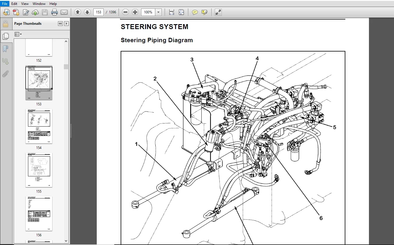
STRUCTURE AND FUNCTION:
This section explains the structure and function of each component. It serves not only to give an understanding of the structure, but also serves as reference material for troubleshooting.
STANDARD VALUE TABLE:
This section explains the standard values for new machine and judgement criteria for testing, adjusting and troubleshooting. This standard value table is used to check the standard values in testing and adjusting and to judge parts in troubleshooting.
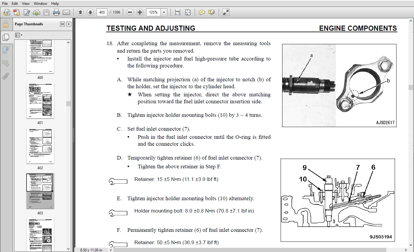
TESTING AND ADJUSTING:
This section explains checks to be made before and after performing repairs, as well as adjustments to be made at completion of the checks and repairs.
TROUBLESHOOTING:
This section explains how to find out failed parts and how to repair them. The troubleshooting is divided by failure modes. The “S mode” of the troubleshooting related to the engine may be also explained in the
DISASSEMBLY AND ASSEMBLY
This section explains the order to be followed when removing, installing, disassembling or assembling each component, as well as precautions to be taken for these operations.
MAINTENANCE STANDARD
This section gives the judgement standards when inspecting disassembled parts.
AIR CONDITIONING
This section explains the air conditioning system, structure and function, troubleshooting, disassembly, and assembly.
DIAGRAMS AND DRAWINGS
This section has the foldout drawings for the machine.
TABLE OF CONTENTS:
Komatsu WA320-6 Wheel Loader Shop Manual
CEBM022801 - WA320-6 snA35001 and up..........................................................   1
	CONTENTS..................................................................................   2
	REVISED PAGES.............................................................................   3
	SAFETY....................................................................................  15
		Safety Notice.........................................................................  15
			IMPORTANT SAFETY NOTICE...........................................................  15
			General Precautions...............................................................  15
			Preparations for Work.............................................................  16
			Precautions During Work...........................................................  16
		Seat Belt Inspection..................................................................  17
	GENERAL...................................................................................  18
	HOW TO READ THE SHOP MANUAL...............................................................  19
		Volumes...............................................................................  19
		Distribution and Updating.............................................................  19
		Filing Method.........................................................................  19
		Revised Edition Mark..................................................................  19
		Revisions.............................................................................  19
		Symbols...............................................................................  19
	HOISTING INSTRUCTIONS.....................................................................  20
		Hoisting..............................................................................  20
		Making Signs/Hand Signals.............................................................  20
		Precautions...........................................................................  20
			Precautions for Sling Work........................................................  20
			Precautions for Using Mobile Crane................................................  21
			Precautions for Using Overhead Hoist Crane........................................  21
		Selecting Wire Ropes..................................................................  22
	AIR CONDITIONER CIRCUITS..................................................................  23
		Precautions for Handling Hoses and Tubes..............................................  23
			Disconnecting Hoses and Tubes.....................................................  23
			Connecting Hoses and Tubes........................................................  23
	MAINTENANCE STANDARD TERMS................................................................  24
	HANDLING ELECTRIC AND HYDRAULIC EQUIPMENT.................................................  26
		Handling Electric Equipment...........................................................  26
			Handling Wiring Harnesses and Connectors..........................................  26
			Main Failures Occurring in Wiring Harness.........................................  26
			Removing, Installing, and Drying Connectors and Wiring Harnesses..................  27
			Handling Controller...............................................................  31
			Troubleshooting Electric Circuits.................................................  31
		Handling Hydraulic Equipment..........................................................  32
		Handling Connectors Used for Engines..................................................  33
			Slide Lock Type...................................................................  33
			Pull Lock Type....................................................................  34
			Push Lock Type....................................................................  34
			Turn-housing Type (Round Green Connector).........................................  36
	PRECAUTIONS FOR OPERATIONS................................................................  37
		Precautions when Carrying Out Removal Work............................................  37
		Precautions when Carrying Out Installation Work.......................................  38
		Precautions when Completing the Operation.............................................  39
	PUSH-PULL COUPLER.........................................................................  40
		Type 1................................................................................  40
			Disconnection.....................................................................  40
			Connection........................................................................  40
		Type 2................................................................................  41
			Disconnection.....................................................................  41
			Connection........................................................................  41
		Type 3................................................................................  42
			Disconnection.....................................................................  42
			Connection........................................................................  42
	COATING MATERIALS.........................................................................  43
	STANDARD TIGHTENING TORQUE................................................................  45
		Standard Tightening Tables............................................................  45
			For Bolts and Nuts................................................................  45
			For Split Flange Bolts............................................................  46
			For O-Ring Boss Piping Joints.....................................................  46
			For O-Ring Boss Plugs.............................................................  47
			For Hoses (Taper-Seal Type and Face-Seal Type)....................................  47
			For Face Seal Joints..............................................................  48
			For 102, 107, and 114 Engine Series (Bolts and Nuts)..............................  48
			For 102, 107, and 114 Engine Series (Eye Joints)..................................  49
			For 102, 107, and 114 Engine Series (Taper Screws)................................  49
	CONVERSION TABLES.........................................................................  50
		Method of Using the Conversion Table..................................................  50
01 GENERAL....................................................................................  57
	SPECIFICATIONS............................................................................  58
		Dimension Drawing.....................................................................  58
		Specification Tables..................................................................  60
	WEIGHT TABLE..............................................................................  66
	FUEL, COOLANT, AND LUBRICANTS.............................................................  68
10 STRUCTURE, FUNCTION ANDMAINTENANCE STANDARD................................................  71
	ENGINE AND COOLING SYSTEM.................................................................  75
		Engine and Transfer Mount.............................................................  75
		Damper................................................................................  76
		Cooling System........................................................................  78
		Cooling System Hydraulic Piping Diagram...............................................  79
		Cooling Fan Motor.....................................................................  80
			Hydraulic Motor...................................................................  84
			Suction Safety Valve..............................................................  85
			Reversible Valve..................................................................  87
			Flow Control Valve (continuously-variable type)...................................  88
	POWER TRAIN SYSTEM........................................................................  89
		Drive Line Components.................................................................  89
		Power Train System Diagram............................................................  90
		Drive Shaft...........................................................................  92
		HST Hydraulic Piping Diagram..........................................................  93
		HST Pump..............................................................................  94
			Operation.........................................................................  96
			High-Pressure Relief Valve........................................................  97
			Low-pressure Relief Valve.........................................................  99
			HST Charge Pump................................................................... 100
			Speed-Related Valve (DA Valve).................................................... 102
			High-Pressure Cutoff Valve........................................................ 103
		HST Motor............................................................................. 104
			HST Motor 1....................................................................... 104
			HST Motor 2....................................................................... 106
			EP Servo Valve.................................................................... 108
			HA Servo Valve.................................................................... 109
			Directional Shuttle Valve......................................................... 110
		Transfer.............................................................................. 112
			Input Shaft....................................................................... 116
			Output Shaft...................................................................... 120
			Outline........................................................................... 124
			Operation of Clutch............................................................... 125
			Power Transmitting Route.......................................................... 126
			Clutch Solenoid Valve............................................................. 128
	DRIVE AXLE SYSTEM......................................................................... 130
		Front and Rear Axles.................................................................. 130
			Front Axle........................................................................ 130
			Rear Axle......................................................................... 132
		Differential.......................................................................... 134
			Front Differential................................................................ 134
			Rear Differential................................................................. 138
			Torque Proportioning Differential................................................. 142
			Limited Slip Differential (if equipped)........................................... 144
		Final Drive........................................................................... 148
			Front Final Drive................................................................. 148
			Rear Final Drive.................................................................. 150
	STEERING SYSTEM........................................................................... 153
		Steering Piping Diagram............................................................... 153
		Steering Column....................................................................... 154
		Priority Valve........................................................................ 155
		Orbitrol Valve........................................................................ 159
			Operation......................................................................... 162
			Connection of Hand Pump and Sleeve................................................ 166
		Cushion Valve......................................................................... 168
		Steering Cylinder..................................................................... 170
		Emergency Steering Piping Diagram (if equipped)....................................... 172
		Emergency Steering Valve (if equipped)................................................ 174
		Steering Relief Valve (if equipped)................................................... 178
	BRAKE SYSTEM.............................................................................. 180
		Brake Piping Diagram.................................................................. 180
		Charge Valve.......................................................................... 182
		Brake Valve........................................................................... 186
		Braking Operation..................................................................... 188
		Inching Valve......................................................................... 191
		Accumulator (for Brake)............................................................... 192
		Slack Adjuster........................................................................ 194
		Brakes................................................................................ 196
			Front Brake....................................................................... 196
			Rear Brake........................................................................ 198
		Parking Brake System.................................................................. 201
			Brake Control..................................................................... 201
			Parking Brake..................................................................... 202
	UNDERCARRIAGE AND FRAME................................................................... 204
		Axle Mounting and Center Hinge Pin.................................................... 204
		Tires................................................................................. 209
			Radial Tire....................................................................... 209
			Bias Tire......................................................................... 210
	HYDRAULIC SYSTEM.......................................................................... 212
		Work Equipment Hydraulic Piping Diagram............................................... 212
		Work Equipment Control Lever Linkage.................................................. 214
			Multi-Function Mono-Lever Type.................................................... 214
			2-Lever Type (if equipped)........................................................ 215
		Hydraulic Tank........................................................................ 216
			Breather.......................................................................... 217
		4-Gear Pump........................................................................... 218
		Work Equipment Control Valve.......................................................... 220
			2-Spool Type...................................................................... 220
			3-Spool Type...................................................................... 224
			Relief Valve...................................................................... 228
			Safety-Suction Valve.............................................................. 229
			Suction Valve..................................................................... 230
			Operation of Work Equipment Control Valve......................................... 231
		Cutoff Valve.......................................................................... 238
		PPC Valve............................................................................. 241
			Work Equipment PPC Valve: Mono Lever Type......................................... 241
			Work Equipment PPC Valve: 2-Lever Type (if equipped).............................. 247
			Attachment PPC Valve.............................................................. 254
		Lock Valve (for PPC Circuit).......................................................... 256
		Accumulator (for PPC Circuit)......................................................... 257
		ECSS Valve............................................................................ 258
		Accumulator (for ECSS)................................................................ 261
	Work Equipment............................................................................ 262
		Work Equipment Linkage................................................................ 262
		Bucket................................................................................ 264
		Bucket Positioner and Boom Kickout.................................................... 266
			Operation of Proximity Switch..................................................... 268
		Work Equipment Cylinders.............................................................. 274
			Lift Cylinder..................................................................... 274
			Bucket Cylinder................................................................... 274
	CAB ENVIRONMENT........................................................................... 275
		Cab................................................................................... 275
		Air Conditioner....................................................................... 276
			Air Conditioner Piping Diagram.................................................... 276
			Refrigerant Circuit Diagram....................................................... 278
			Air Conditioner Unit.............................................................. 279
			Blower and Intake Unit............................................................ 282
			Compressor........................................................................ 284
			Condenser......................................................................... 285
			Receiver.......................................................................... 286
			Air Conditioner Panel............................................................. 288
	ELECTRICAL SYSTEM......................................................................... 292
		Machine Monitor System................................................................ 292
			System Circuit Diagram............................................................ 294
			Machine Monitor................................................................... 296
			Items Displayed on Monitor........................................................ 297
		Machine Monitor Operation Switches.................................................... 306
			Setting Machine Monitor........................................................... 307
			Troubleshooting Function.......................................................... 308
			Character Display Function........................................................ 308
			Operator Mode Functions........................................................... 309
			Service Mode Functions............................................................ 312
			Input and Output Signals.......................................................... 317
		Electrical System (HST Controller System)............................................. 325
			Input and Output Signals Diagram.................................................. 325
			HST Controller Gearshifting Control Function...................................... 326
			HST Controller Protection Function................................................ 332
			Cooling Fan Control Function...................................................... 335
			System Circuit Diagram............................................................ 340
		HST Controller........................................................................ 343
		ECSS System........................................................................... 345
	ELECTRONIC TRANSMISSION CONTROL........................................................... 347
		KOMTRAX Terminal System............................................................... 347
			KOMTRAX Terminal.................................................................. 349
		Engine Starting Circuit............................................................... 351
		Engine Stopping Circuit............................................................... 353
		Preheating Circuit.................................................................... 354
		Engine Output Lowering Function....................................................... 355
		Automatic Warm-up Function............................................................ 355
		Parking Brake Circuit................................................................. 356
		Max. Traction Switch (if equipped).................................................... 358
		Multi-Function Knob................................................................... 359
			Modification of Multi-Function Lever.............................................. 360
		Sensors............................................................................... 363
			Speed Sensor...................................................................... 363
			HST Oil Temperature Sensor........................................................ 365
			Brake Oil Temperature Sensor...................................................... 365
			HST Oil Pressure Sensor........................................................... 366
			HST Oil Filter Clogging Sensor.................................................... 366
			Coolant Level Sensor.............................................................. 367
			Fuel Level Sensor................................................................. 368
			Accelerator Pedal Sensor.......................................................... 369
			Air Cleaner Clogging Sensor....................................................... 371
			Water-in-Fuel Sensor.............................................................. 372
			Boom Kick-Out Proximity Switch.................................................... 373
			Bucket Positioner Proximity Switch................................................ 373
20 STANDARD VALUE TABLES...................................................................... 375
	STANDARD VALUE TABLES..................................................................... 377
		Standard Value Table for Engine....................................................... 377
		Standard Value Table for Chassis...................................................... 378
	MACHINE POSTURE........................................................................... 383
30 TESTING AND ADJUSTING...................................................................... 385
	TOOLS..................................................................................... 389
		Tools for Testing, Adjusting, and Troubleshooting..................................... 389
	ENGINE COMPONENTS......................................................................... 395
		Engine Speed.......................................................................... 395
			Measure Engine Speed (Low and High Idle).......................................... 395
			Measure HST Stall Speed........................................................... 395
			Measure Hydraulic Stall Speed..................................................... 396
			Measure HST Stall and Hydraulic Stall (Full Stall) Speed.......................... 396
		Exhaust Gas Color..................................................................... 397
			Using Handy Smoke Checker A1...................................................... 397
			Using Smoke Meter A2.............................................................. 397
		Adjusting Valve Clearance............................................................. 399
		Measuring Engine Compression.......................................................... 401
		Measuring Blow-by Pressure............................................................ 404
		Measuring Engine Oil Pressure......................................................... 406
		Intake Air (Boost) Pressure........................................................... 407
			Measuring with Monitoring Function................................................ 407
			Measuring with Measuring Tool..................................................... 408
	FUEL SYSTEM............................................................................... 409
		Handling Fuel System Equipment........................................................ 409
		Releasing Residual Pressure in Fuel System............................................ 409
		Measuring Fuel Pressure............................................................... 410
			Measuring Pressure in Fuel Low-pressure Circuit................................... 410
			Measuring Pressure in Fuel Return Circuit......................................... 411
			Measuring Fuel Negative-Pressure Circuit Pressure................................. 412
		Fuel Delivery, Return, and Leak Rate.................................................. 413
			Measuring Supply Pump Delivery.................................................... 413
			Measuring Return Rate from Supply Pump............................................ 415
			Measuring Leakage from Pressure Limiter........................................... 416
			Measuring Return Rate from Injector............................................... 417
		Bleeding Air from Fuel Circuit........................................................ 418
		Testing Leakage in Fuel System........................................................ 419
		Handling Reduced Cylinder Mode Operation.............................................. 420
		Handling No-Injection Cranking Operation.............................................. 420
		Handling Controller Voltage Circuit................................................... 420
	EXHAUST SYSTEM AND PIPING................................................................. 421
		Checking Muffler and Muffler Stack for Looseness and Damage........................... 421
		Checking Muffler Function............................................................. 421
		Checking Installed Condition of Cylinder Head and Manifolds........................... 421
		Checking Engine Piping for Damage and Looseness....................................... 421
	BELTS..................................................................................... 422
		Air Conditioner Compressor Belt....................................................... 422
			Testing the Tension............................................................... 422
			Adjusting the Tension............................................................. 422
		Replacing Alternator Belt............................................................. 423
	ACCELERATOR PEDAL......................................................................... 424
		Testing Operating Effort.............................................................. 424
		Testing Operating Angle............................................................... 425
	DIRECTIONAL LEVER......................................................................... 426
		Checking Operating Effort............................................................. 426
		Checking Travel....................................................................... 426
	POWER TRAIN OIL PRESSURES................................................................. 427
		HST Oil Pressure...................................................................... 427
			Testing High-Pressure Cutoff Oil Pressure......................................... 427
			Testing Low-Pressure Relief Pressure.............................................. 428
			Testing Servo Piston Control Pressure (DA Pressure)............................... 429
			Testing Servo Piston Actuating Pressure........................................... 430
			Adjusting High-Pressure Cutoff Valve.............................................. 430
			Adjusting Low-Pressure Relief Valve............................................... 431
			Adjusting DA Pressure............................................................. 432
		Testing Clutch Control Pressure....................................................... 433
	STEERING SYSTEM........................................................................... 435
		Steering Wheel........................................................................ 435
			Measuring Play.................................................................... 435
			Measuring Operating Effort........................................................ 436
			Measuring Operating Time.......................................................... 436
		Steering Oil Pressure................................................................. 437
			Measuring Main Relief Pressure.................................................... 437
			Adjusting Main Relief Pressure.................................................... 439
		Bleeding Air from Steering Circuit.................................................... 440
	HYDRAULIC DRIVE FAN....................................................................... 441
		Measuring Fan Speed................................................................... 441
		Measuring Fan Drive Oil Pressure...................................................... 442
	WHEEL BRAKE SYSTEM........................................................................ 443
		Measuring Pressing Angle of Brake Pedal............................................... 443
		Brake Pedal Linkage................................................................... 444
			Testing........................................................................... 444
			Adjusting......................................................................... 444
		Measuring Brake Performance........................................................... 445
		Accumulator Charge.................................................................... 446
			Measuring......................................................................... 446
			Adjusting......................................................................... 447
		Measuring Brake Oil Pressure.......................................................... 448
		Testing Wear of Wheel Brake Disc...................................................... 451
		Bleeding Air from Brake Circuit....................................................... 452
		Releasing Residual Pressure in Brake Accumulator Circuit.............................. 453
	PARKING BRAKE SYSTEM...................................................................... 454
		Testing Parking Brake Performance..................................................... 454
		Parking Brake Control Cable........................................................... 455
			Testing........................................................................... 455
			Adjusting......................................................................... 455
	WORK EQUIPMENT SYSTEM..................................................................... 456
		Work Equipment Control Lever.......................................................... 456
			Measuring Operating Effort........................................................ 456
			Measuring Travel.................................................................. 456
		Work Equipment Hydraulic Pressure..................................................... 457
			Measuring......................................................................... 457
			Adjusting......................................................................... 457
		PPC Oil Pressure...................................................................... 459
			Measuring PPC Valve Basic Pressure................................................ 459
			Measuring PPC Valve Output Pressure............................................... 460
		Bleeding Air from Hydraulic Circuit................................................... 461
			Bleeding Air from Work Equipment PPC Circuit...................................... 461
			Bleeding Air from Cylinders....................................................... 461
		Releasing Residual Pressure in Hydraulic Circuit...................................... 462
			Between Each Hydraulic Cylinder and Control Valve................................. 462
			In Brake Accumulator Circuit...................................................... 462
			In PPC Accumulator Circuit........................................................ 462
		Work Equipment Positioners............................................................ 463
			Bucket Positioner................................................................. 463
			Boom Kickout Switch............................................................... 464
		Proximity Switch Operation Pilot Lamp................................................. 465
	ELECTRICAL SYSTEM TROUBLESHOOTING......................................................... 466
		Procedure for Testing Diodes.......................................................... 466
			When Using Digital Type Circuit Tester............................................ 466
			When Using Analog Type Circuit Tester............................................. 467
		Preparation for Troubleshooting Electric System....................................... 468
			Machine Monitor................................................................... 468
			HST Controller.................................................................... 469
			KOMTRAX Terminal.................................................................. 470
		Sensors............................................................................... 471
			Boost Pressure and Temperature Sensor (BOOST PRESS & IMT)......................... 471
			Supply Pump IMV Solenoid (FUEL REGULATOR)......................................... 471
			Common Rail Pressure Sensor (FUEL RAIL PRESS)..................................... 472
			Engine Coolant Temperature Sensor (COOLANT TEMP).................................. 472
	KOMTRAX TERMINAL SYSTEM................................................................... 473
		Terminal Installed at Plant Before Shipment........................................... 473
		Terminal Retrofitted Machine After Shipment........................................... 473
		Starting Operation.................................................................... 473
			Application for the Start of Use.................................................. 476
		Komtrax Terminal Lamps................................................................ 477
			Contents of 7-Segment and Dot Displays for CPU.................................... 479
	MACHINE MONITOR SYSTEM.................................................................... 480
		Adjusting Machine Monitor............................................................. 480
		Adjusting for Replaced, Reassembled, or Added Sensor/Controller....................... 481
		Adjustment for User’s Needs........................................................... 482
		Special Functions of Machine Monitor (EMMS)........................................... 483
			Normal and Special Functions of Machine Monitor................................... 484
		Functions and Flow of Service Mode.................................................... 485
		Operator Mode......................................................................... 488
			Service Meter Display Function (1)................................................ 488
			Traction Level Selection Function (2)............................................. 488
			HST Function Selection Function (3)............................................... 488
			Odometer Display Function (4)..................................................... 489
			Maintenance Monitoring Function (5)............................................... 489
			Telephone Number Input Function (6)............................................... 489
			Language Selection Function (7)................................................... 489
			Monitor Brightness Adjustment Function (8)........................................ 490
			Travel Speed/Engine Speed Display Selecting Function (9).......................... 490
			Travel Speed/Engine Speed Display/Non-Display Selecting Function (10)............. 491
			Action Code Display Function (11)................................................. 491
			Failure Code Display Function (12)................................................ 492
		Service Mode.......................................................................... 493
			Switching to Service Mode and Screen Display (1).................................. 493
			Electrical System Fault History Display Function (ELECTRIC FAULT) (2)............. 495
			Mechanical System Fault History Display Function (MACHINE FAULT) (3).............. 497
			Real-Time Monitoring Function (REAL-TIME MONITOR) (4)............................. 498
			Real-Time Monitoring Code Tables.................................................. 501
			Engine Reduced-Cylinder Function (CYLINDER CUT-OUT) (5)........................... 515
			No-Injection Cranking Function (6)................................................ 516
			Adjustment Function (TUNING) (7).................................................. 517
			Maintenance Monitoring Function (8)............................................... 521
			Operating Information Display Function (9)........................................ 527
			Optional Device Selecting Function (10)........................................... 530
			Machine Serial Number Input Function (11)......................................... 534
			Model Select Function (MACHINE WA***) (12)........................................ 534
			Initialize Function (13).......................................................... 535
			Setting Procedure for Service Meter and Odometer.................................. 536
	PM-CLINIC INSPECTION TABLE................................................................ 540
40 TROUBLESHOOTING............................................................................ 545
	POINTS TO REMEMBER WHEN TROUBLESHOOTING................................................... 555
	SEQUENCE OF EVENTS IN TROUBLESHOOTING..................................................... 557
	PRECAUTIONS WHEN CARRYING OUT MAINTENANCE................................................. 558
		Precautions when Handling Electrical Equipment........................................ 558
		Handling Electronic Control Unit...................................................... 563
		Points to Remember when Troubleshooting Electrical Circuits........................... 564
		Handling Hydraulic Equipment.......................................................... 565
	ELECTRIC WIRE CODE........................................................................ 567
		How to Read Electric Wire Code........................................................ 567
		Type, Symbol, and Material............................................................ 567
		Dimensions............................................................................ 568
		Color Codes Table..................................................................... 569
		Types of Circuits and Color Codes..................................................... 570
		Classification by Thickness........................................................... 570
		Classification by Color and Code...................................................... 571
	CHECKS BEFORE TROUBLESHOOTING............................................................. 572
		Categories and Method of Using Troubleshooting Charts................................. 573
		Troubleshooting Individual Electrical Circuits........................................ 574
			Chart Use......................................................................... 576
			Chart Tips........................................................................ 576
		Troubleshooting Individual Hydraulic Circuits......................................... 577
	CONNECTION TABLE FOR CONNECTOR PIN NUMBERS................................................ 579
		X-Type Connectors..................................................................... 579
		SWP-Type Connectors................................................................... 581
		M-Type Connectors..................................................................... 583
		S-Type Connectors..................................................................... 585
		MIC-Type Connectors................................................................... 587
		AMP040-Type Connectors................................................................ 589
		AMP070-Type Connectors................................................................ 591
		Miscellaneous Types of Connectors..................................................... 593
		HD30 Series Connectors................................................................ 597
		DT Series Connectors.................................................................. 602
		DTM Series Connectors................................................................. 604
		DTHD Series Connectors................................................................ 604
		DTP Series Connectors................................................................. 605
		DRC26 Series Connectors............................................................... 606
		DRC12, 16 Connectors.................................................................. 608
		AMP Connectors for Pump Controller (CH700)............................................ 609
		BOSCH Connectors for Engine........................................................... 611
		SUMITOMO Connectors for Engine........................................................ 612
		CANNON Connectors for Engine.......................................................... 613
		AMP Connectors for Engine............................................................. 614
		FRAMATOME Connectors for Engine....................................................... 615
		PACKARD Connectors for Engine......................................................... 617
		OT Series Connectors for Engine....................................................... 618
	T-BRANCH BOX and T-BRANCH ADAPTER TABLE................................................... 619
	MODE CHART................................................................................ 624
	INFORMATION CONTAINED IN TESTING PROCEDURES............................................... 627
	TROUBLESHOOTING BY FAILURE CODE........................................................... 629
		Failure Code Table.................................................................... 629
	FUSE BOX AND SLOW-BLOW FUSES.............................................................. 635
		Connection Table of Fuse Box and Slow-Blow Fuses...................................... 635
			Fuse Box: FS1..................................................................... 635
			Fuse Box: FS2..................................................................... 636
			Slow-Blow Fuses................................................................... 637
	FAILURE CODES............................................................................. 638
		2G40ZG................................................................................ 640
			Brake: Oil Pressure Reduction..................................................... 640
		6091NX................................................................................ 642
			HST Filter: Clogging.............................................................. 642
		989FN1................................................................................ 643
			Travel Speed: Overrun Alarm....................................................... 643
		AA1ANX................................................................................ 644
			Air Cleaner: Clogging............................................................. 644
		AB00L6................................................................................ 646
			Alternator R System: Hot Short.................................................... 646
		AB00MA................................................................................ 648
			Alternator R System: Ground Fault/Disconnection/Low Charge Voltage................ 648
		B@BAZG................................................................................ 650
			Engine: Oil Pressure Reduction.................................................... 650
		B@BAZK................................................................................ 651
			Engine Oil: Low Level............................................................. 651
		B@BCNS................................................................................ 652
			Engine: Overheat.................................................................. 652
		B@BCZK................................................................................ 654
			Engine: Low Coolant Level......................................................... 654
		B@C6NS................................................................................ 656
			Front Brake: High Oil Temperature................................................. 656
		B@CRNS................................................................................ 657
			HST: High Oil Temperature......................................................... 657
		CA111................................................................................. 658
			Abnormality in Engine Controller.................................................. 658
		CA115................................................................................. 659
			Engine Ne or Bkup Speed Sensor Error.............................................. 659
		CA122................................................................................. 660
			Charge Pressure Sensor High Error................................................. 660
		CA123................................................................................. 662
			Charge Pressure Sensor Low Error.................................................. 662
		CA131................................................................................. 664
			Throttle Sensor High Error........................................................ 664
		CA132................................................................................. 666
			Throttle Sensor Low Error......................................................... 666
		CA144................................................................................. 668
			Coolant Sensor High Error......................................................... 668
		CA145................................................................................. 670
			Coolant Sensor Low Error.......................................................... 670
		CA153................................................................................. 672
			Charge Temperature Sensor High Error.............................................. 672
		CA154................................................................................. 674
			Charge Temperature Sensor Low Error............................................... 674
		CA155................................................................................. 676
			Lowering of Speed by Abnormally High Charge Temperature........................... 676
		CA187................................................................................. 678
			Sensor Power Supply 2 Low Error................................................... 678
		CA221................................................................................. 680
			Atmospheric Pressure Sensor High Error............................................ 680
		CA222................................................................................. 682
			Atmospheric Sensor Low Error...................................................... 682
		CA227................................................................................. 684
			Sensor Power Supply 2 High Error.................................................. 684
		CA234................................................................................. 686
			Engine Overspeed.................................................................. 686
		CA238................................................................................. 687
			Ne Speed Sensor Power Supply Error................................................ 687
		CA271................................................................................. 688
			IMV (IMA) Short Circuit........................................................... 688
		CA272................................................................................. 690
			IMV (IMA) Disconnection........................................................... 690
		CA322................................................................................. 692
			Injector #1 Open/Short Error...................................................... 692
		CA323................................................................................. 694
			Injector #5 Open/Short Error...................................................... 694
		CA324................................................................................. 696
			Injector #3 Open/Short Error...................................................... 696
		CA325................................................................................. 698
			Injector #6 Open/Short Error...................................................... 698
		CA331................................................................................. 700
			Injector #2 Open/Short Error...................................................... 700
		CA332................................................................................. 702
			Injector #4 Open/Short Error...................................................... 702
		CA342................................................................................. 704
			Calibration Code Inconsistency.................................................... 704
		CA351................................................................................. 706
			Injectors Drive Circuit Error..................................................... 706
		CA352................................................................................. 708
			Sensor Power Supply 1 Low Error................................................... 708
		CA386................................................................................. 710
			Sensor Power Supply 1 High Error.................................................. 710
		CA428................................................................................. 712
			Abnormally High Level in Water Sensor............................................. 712
		CA429................................................................................. 714
			Abnormally Low Level in Water Sensor.............................................. 714
		CA431................................................................................. 716
			Idle Validation Switch Error...................................................... 716
		CA432................................................................................. 720
			Idle Validation Action Error...................................................... 720
		CA435................................................................................. 724
			Engine Oil Pressure Switch Error.................................................. 724
		CA441................................................................................. 726
			Battery Voltage Low Error......................................................... 726
		CA442................................................................................. 730
			Battery Voltage High Error........................................................ 730
		CA449................................................................................. 732
			Common Rail Pressure High Error 2................................................. 732
		CA451................................................................................. 734
			Common Rail Pressure Sensor High Error............................................ 734
		CA452................................................................................. 736
			Common Rail Pressure Sensor Low Error............................................. 736
		CA488................................................................................. 738
			Lowering of Torque by Abnormally High Charge Temperature.......................... 738
		CA553................................................................................. 739
			Common Rail Pressure High Error 1................................................. 739
		CA559................................................................................. 740
			Supply Pump Pressure Very Low Error............................................... 740
		CA689................................................................................. 742
			Engine Ne Speed Sensor Error...................................................... 742
		CA731................................................................................. 744
			Engine Bkup Speed Sensor Phase Error.............................................. 744
		CA757................................................................................. 745
			All Continuous Data Lost Error.................................................... 745
		CA778................................................................................. 748
			Engine Bkup Speed Sensor Error.................................................... 748
		CA1633................................................................................ 750
			KOMNET Datalink Timeout Error..................................................... 750
		CA2185................................................................................ 754
			Throttle Sensor Supply Voltage High Error......................................... 754
		CA2186................................................................................ 756
			Throttle Sensor Power Supply Low Error............................................ 756
		CA2249................................................................................ 758
			Supply Pump Pressure Very Low Error 2............................................. 758
		CA2311................................................................................ 760
			Abnormality in IMV (IMA) Solenoid................................................. 760
		CA2555................................................................................ 762
			Intake Heater Relay Disconnection Error........................................... 762
		CA2556................................................................................ 764
			Intake Heater Relay Short Circuit Error........................................... 764
		D160KY................................................................................ 766
			Backup Alarm/Lamp Relay 1 Circuit: Hot Short...................................... 766
		D192KY................................................................................ 768
			ECSS Solenoid Relay: Hot Short.................................................... 768
		D1B0KA................................................................................ 770
			HST Safety Relay: Disconnection................................................... 770
		D1B0KB................................................................................ 772
			HST Safety Relay: Ground Fault.................................................... 772
		D1B0KY................................................................................ 774
			HST Safety Relay: Hot Short....................................................... 774
		D5ZHL6................................................................................ 776
			IGN C System: Ground Fault/Disconnection.......................................... 776
		DAF3KK................................................................................ 778
			UNSW Power Supply: Ground Fault/Disconnection..................................... 778
		DAFRKR................................................................................ 780
			Machine Monitor CAN-NET Signal: Disconnection..................................... 780
		DAJ0KK................................................................................ 782
			HST Controller Power Supply: Low Voltage.......................................... 782
		DAJ0KT................................................................................ 784
			HST Controller Memory (EEPROM): Abnormality....................................... 784
		DAJ1L4................................................................................ 786
			HST Controller Main Power Line: Disconnection/Ground Fault........................ 786
		DAJ1L6................................................................................ 788
			HST Controller Main Power Line: Hot Short......................................... 788
		DAJ2KK................................................................................ 790
			Controller Solenoid Power Supply: Low Voltage..................................... 790
		DAJ2L3................................................................................ 792
			HST Controller Load Power Supply Holding Line: Hot Short in Wiring Harness........ 792
		DAJ2L4................................................................................ 794
			HST Controller Load Power Supply Holding Line: Disconnection/Ground Fault......... 794
		DAJ5KX................................................................................ 796
			Sensor 5V Power Supply: Out-of-Output Range....................................... 796
		DAJ9KQ................................................................................ 798
			HST Controller Model Selection: Disagreement of Model Selection Signals........... 798
		DAJRKR................................................................................ 800
			HST Controller CAN-NET Signal: Disconnection...................................... 800
		DAJRMA................................................................................ 805
			HST Controller: Disagreement in Option Selection.................................. 805
		DB2RKR................................................................................ 806
			Engine Controller CAN-NET: Disconnection in Signal Line........................... 806
		DD1NL4................................................................................ 812
			Fan Automatic Reverse Switch Signal: Abnormality.................................. 812
		DD1NLD................................................................................ 814
			Fan Reverse Switch Signal: Abnormality............................................ 814
		DDB6KA................................................................................ 816
			Parking Brake Reminder Signal: Disconnection/Short Circuit........................ 816
		DDB6KB................................................................................ 818
			Parking Brake Indicator Signal: Ground Fault...................................... 818
		DDB6KZ................................................................................ 820
			Parking Brake Switch or Parking Brake Reminder Switch: Trouble.................... 820
		DDB6L0................................................................................ 822
			Parking Brake Reminder Signal: Ground Fault....................................... 822
		DDB6L4................................................................................ 824
			Parking Brake Indicator Signal: Disconnection/Hot Short........................... 824
		DDD7KX................................................................................ 826
			Travel Speed Control Dial Signal: Disconnection/Ground Fault...................... 826
		DDD7KY................................................................................ 828
			Travel Speed Control Dial Signal: Hot Short....................................... 828
		DDE5MA................................................................................ 830
			Emergency Steering Operation Switch: Disconnection................................ 830
		DDK3KA................................................................................ 832
			Directional Selector Switch: Disconnection/Hot Short.............................. 832
		DDK3KB................................................................................ 834
			Directional Selector Switch: Ground Fault......................................... 834
		DDK6KA................................................................................ 836
			FNR Lever: Disconnection/Ground Fault............................................. 836
		DDK6KY................................................................................ 840
			FNR Lever: Hot Short.............................................................. 840
		DDS5L6................................................................................ 842
			Steering: Low Oil Pressure (Operation of Emergency Steering)...................... 842
		DF10KA................................................................................ 844
			Travel Speed Range Selector Switch: Disconnection/Ground Fault.................... 844
		DF10KB................................................................................ 848
			Travel Speed Range Selector Switch: Hot Short..................................... 848
		DGH1KX................................................................................ 850
			HST Oil Temperature Sensor: Ground Fault.......................................... 850
		DGR2KB................................................................................ 852
			Brake Oil Temperature Sensor: Ground Fault........................................ 852
		DGR2KZ................................................................................ 854
			Brake Oil Temperature Sensor: Disconnection/Hot Short............................. 854
		DHH1KX................................................................................ 856
			HST Oil Pressure Sensor: Disconnection/Ground Fault............................... 856
		DHH1KY................................................................................ 858
			HST Oil Pressure Sensor: Hot Short................................................ 858
		DHTCL6................................................................................ 860
			HST Filter Clogging Sensor: Functional Defect..................................... 860
		DJF1KA................................................................................ 862
			Fuel Level Sensor: Disconnection/Hot Short........................................ 862
		DLT3KX................................................................................ 864
			Travel Speed Sensor B: Abnormality................................................ 864
		DLT4KX................................................................................ 868
			Travel Speed Sensor A: Abnormality................................................ 868
		DLT4LC................................................................................ 870
			Travel Speed Sensor A & B: Abnormality............................................ 870
		DV00KY................................................................................ 872
			Alarm Buzzer: Hot Short........................................................... 872
		DW26KA................................................................................ 874
			Motor 2 Solenoid: Disconnection/Ground Fault...................................... 874
		DW26KY................................................................................ 876
			Motor 2 Solenoid: Hot Short....................................................... 876
		DW7BKY................................................................................ 878
			Fan Reverse Solenoid Circuit: Hot Short........................................... 878
		DW7BKZ................................................................................ 880
			Fan Reverse Solenoid Circuit: Disconnection/Ground Fault.......................... 880
		DX16KA................................................................................ 882
			Fan EPC Solenoid: Disconnection................................................... 882
		DX16KB................................................................................ 884
			Fan EPC Solenoid: Ground Fault.................................................... 884
		DX16KY................................................................................ 886
			Fan EPC Solenoid: Hot Short....................................................... 886
		DX19KA................................................................................ 888
			Motor 1 Solenoid: Disconnection................................................... 888
		DX19KB................................................................................ 890
			Motor 1 Solenoid: Ground Fault.................................................... 890
		DX19KY................................................................................ 892
			Motor 1 Solenoid: Hot Short....................................................... 892
		DX20KA................................................................................ 894
			Clutch EPC Solenoid: Disconnection................................................ 894
		DX20KB................................................................................ 896
			Clutch EPC Solenoid: Ground Fault................................................. 896
		DX20KY................................................................................ 898
			Clutch EPC Solenoid: Hot Short.................................................... 898
		DXH7KB................................................................................ 900
			Reverse Solenoid: Ground Fault.................................................... 900
		DXH7KZ................................................................................ 902
			Reverse Solenoid: Disconnection/Hot Short......................................... 902
		DXH8KB................................................................................ 904
			Forward Solenoid: Ground Fault.................................................... 904
		DXH8KZ................................................................................ 906
			Forward Solenoid: Disconnection/Hot Short......................................... 906
		J141N1................................................................................ 908
			Steering Pump: Overrun Alarm...................................................... 908
		M100N1................................................................................ 909
			HST Pump: Overrun Alarm........................................................... 909
		M400N1................................................................................ 910
			Motor 1: Overrun Alarm............................................................ 910
	TROUBLESHOOTING: E-MODE................................................................... 912
		Troubleshooting Electrical System..................................................... 912
			Information in Troubleshooting Table.............................................. 912
		E-1................................................................................... 914
			Engine Does Not Start............................................................. 914
		E-2................................................................................... 922
			Preheater Does Not Operate Manually............................................... 922
		E-3................................................................................... 926
			Travel Speed is Low or High....................................................... 926
		E-4................................................................................... 932
			ECSS Does Not Operate............................................................. 932
		E-5................................................................................... 935
			ECSS Keeps Operating.............................................................. 935
		E-6................................................................................... 938
			Defective Boom Kickout Function and Cancellation.................................. 938
		E-7................................................................................... 942
			Defective Bucket Positioner Function and Cancellation............................. 942
		E-8................................................................................... 946
			Defective Lift Arm FLOATING Holding Function and Cancellation..................... 946
		E-9................................................................................... 950
			Travel Direction Selection System Does Not Function............................... 950
		E-10.................................................................................. 954
			Fan Does Not Reverse.............................................................. 954
		E-11.................................................................................. 958
			Fan Keeps Rotating in Reverse..................................................... 958
		E-12.................................................................................. 960
			Wiper Does Not Operate............................................................ 960
		E-13.................................................................................. 964
			Windshield Washer Does Not Operate................................................ 964
		E-14.................................................................................. 967
			Headlamp, Clearance Lamp, and Tail Lamp Do Not Light Up or Go Off................. 967
		E-15.................................................................................. 975
			Working Lamp Does Not Light Up or Go Off.......................................... 975
		E-16.................................................................................. 980
			Turn Signal Lamp and Hazard Lamp Do Not Light Up or Go Off........................ 980
		E-17.................................................................................. 986
			Brake Lamp Does Not Light or It Keeps Lighting Up................................. 986
		E-18.................................................................................. 988
			Backup Lamp Does Not Light or It Keeps Lighting Up................................ 988
		E-19.................................................................................. 991
			Backup Alarm Does Not Sound or It Keeps Sounding.................................. 991
		E-20.................................................................................. 994
			Horn Does Not Sound or It Keeps Sounding.......................................... 994
		E-21.................................................................................. 996
			Alarm Buzzer Does Not Sound or It Keeps Sounding.................................. 996
		E-22.................................................................................. 998
			Air Conditioner Does Not Operate or Stop.......................................... 998
		E-23..................................................................................1001
			The KOMTRAX System Does Not Work Properly.........................................1001
				Lamp Display Section of KOMTRAX Terminal......................................1003
	TROUBLESHOOTING: H-MODE...................................................................1004
		Table of Failure Codes and Causes.....................................................1006
		Troubleshooting Hydraulic and Mechanical Systems......................................1004
			Method of Using Troubleshooting Chart.............................................1004
		H-1...................................................................................1008
			Machine Does Not Start............................................................1008
		H-2...................................................................................1009
			Travel Speed Is Slow..............................................................1009
		H-3...................................................................................1010
			Traction Force Is Weak............................................................1010
		H-4...................................................................................1011
			Engine Stalls When Traveling or Engine Speed Drops Excessively....................1011
		H-5...................................................................................1012
			Shift Range is Not Shifted........................................................1012
		H-6...................................................................................1013
			Steering Wheel Does Not Turn......................................................1013
		H-7...................................................................................1014
			Steering Wheel Is Heavy...........................................................1014
		H-8...................................................................................1015
			Steering Wheel Shakes or Jerks....................................................1015
		H-9...................................................................................1016
			Machine Deviates Naturally to One Side When Traveling.............................1016
		H-10..................................................................................1017
			Brake Does Not Work or Does Not Work Well.........................................1017
		H-11..................................................................................1018
			Brake Is Not Released or Is Dragged...............................................1018
		H-12..................................................................................1019
			Lift Arm Does Not Rise or Lower...................................................1019
		H-13..................................................................................1020
			Lift Arm Moves Slowly or Lift Arm Rising Force Is Insufficient....................1020
		H-14..................................................................................1021
			When Rising, Lift Arm Starts to Move Slowly at a Specific Height..................1021
		H-15..................................................................................1021
			Lift Arm Cylinder Cannot Hold Down The Bucket (Bucket Rises in the Air)...........1021
		H-16..................................................................................1021
			Hydraulic Drifts of the Lift Arm Occur Often......................................1021
		H-17..................................................................................1022
			Lift Arm Wobbles During Operation.................................................1022
		H-18..................................................................................1022
			When Control Lever Is Switched from HOLD to RAISE, Lift Arm Falls Temporarily.....1022
		H-19..................................................................................1023
			Bucket Does Not Tilt Back.........................................................1023
		H-20..................................................................................1024
			Bucket Moves Slowly or Tilting-Back Force Is Insufficient.........................1024
		H-21..................................................................................1025
			Bucket Starts to Operate Slowly in the Midst of Tilting Back......................1025
		H-22..................................................................................1025
			Bucket Cylinder Cannot Hold Down the Bucket.......................................1025
		H-23..................................................................................1025
			Hydraulic Drifts of the Bucket Occur Often........................................1025
		H-24..................................................................................1026
			Bucket Wobbles During Travel with Load............................................1026
		H-25..................................................................................1026
			When Control Lever Is Switched from HOLD to TILT, the Bucket Falls Temporarily....1026
		H-26..................................................................................1027
			Control Levers of Lift Arm and Bucket Do Not Move Smoothly and Are Heavy..........1027
		H-27..................................................................................1028
			ECSS Does Not Operate and Machine Pitches and Bounces.............................1028
		H-28..................................................................................1029
			Fan Revolution Is Abnormal........................................................1029
50 DISASSEMBLY AND ASSEMBLY...................................................................1031
	HOW TO READ THIS MANUAL...................................................................1035
		Removal and Installation of Assemblies................................................1035
		Disassembly and Assembly of Assemblies................................................1037
	COATING MATERIALS LIST....................................................................1039
	SPECIAL TOOLS LIST........................................................................1043
	SKETCHES OF SPECIAL TOOLS.................................................................1047
	CONNECTOR REPAIR PROCEDURES...............................................................1054
		Stripping Insulation..................................................................1054
		Wire Inspection.......................................................................1054
		Contact Terminal Removal (HD30 Type)..................................................1055
		Crimping Contact Terminal (HD30 Type).................................................1056
		Insertion Of Contact Terminal (HD30 Type).............................................1057
		Contact Terminal Removal (DT Type)....................................................1058
		Crimping Contact Terminal (DT Type)...................................................1059
		Insertion Of Contact Terminal (DT Type)...............................................1060
	ENGINE AND COOLING SYSTEM.................................................................1061
		Fuel Supply Pump Assembly.............................................................1061
			Removal...........................................................................1061
			Installation......................................................................1063
		Fuel Injector Assembly................................................................1064
			Removal...........................................................................1064
			Installation......................................................................1069
		Cylinder Head Assembly................................................................1073
			Removal...........................................................................1073
			Installation......................................................................1082
		Engine Hood Assembly..................................................................1088
			Removal...........................................................................1088
			Installation......................................................................1091
		Radiator..............................................................................1092
			Removal...........................................................................1092
			Installation......................................................................1095
		Air Aftercooler.......................................................................1096
			Removal...........................................................................1096
			Installation......................................................................1097
		Hydraulic Oil Cooler Assembly.........................................................1098
			Removal...........................................................................1098
			Installation......................................................................1100
		Engine Assembly.......................................................................1101
			Removal...........................................................................1101
			Installation......................................................................1107
		Engine Front Oil Seal Assembly........................................................1109
			Removal...........................................................................1109
			Installation......................................................................1111
		Engine Rear Oil Seal Assembly.........................................................1112
			Removal...........................................................................1112
			Installation......................................................................1114
		Cooling Fan and Fan Motor Assembly....................................................1117
			Removal...........................................................................1117
			Installation......................................................................1120
		Fuel Tank Assembly....................................................................1121
			Removal...........................................................................1121
			Installation......................................................................1123
	POWER TRAIN...............................................................................1124
		Transfer..............................................................................1124
			Removal...........................................................................1124
			Installation......................................................................1127
		Transfer Assembly.....................................................................1129
			Disassembly.......................................................................1130
			Assembly..........................................................................1141
		Parking Brake Assembly................................................................1154
			Removal...........................................................................1154
			Installation......................................................................1155
			Disassembly.......................................................................1156
			Assembly..........................................................................1159
		Front Axle Assembly...................................................................1163
			Removal...........................................................................1163
			Installation......................................................................1165
		Rear Axle Assembly....................................................................1166
			Removal...........................................................................1166
			Installation......................................................................1169
		Axle Housing Assembly.................................................................1170
			Disassembly.......................................................................1171
			Assembly..........................................................................1177
		Differential Assembly.................................................................1186
			Disassembly.......................................................................1187
			Assembly..........................................................................1199
	UNDERCARRIAGE AND FRAME...................................................................1217
		Center Hinge Pin......................................................................1217
			Removal...........................................................................1217
			Installation......................................................................1224
		Counterweight.........................................................................1230
			Removal...........................................................................1230
			Installation......................................................................1231
	HYDRAULIC SYSTEM..........................................................................1232
		HST Pump and 4-Gear Pump Assembly.....................................................1232
			Removal...........................................................................1232
			Installation......................................................................1235
		HST Pump Assembly.....................................................................1237
			Disassembly.......................................................................1237
			Assembly..........................................................................1250
		HST Motor 1 Assembly..................................................................1270
			Removal...........................................................................1270
			Installation......................................................................1271
		HST Motor 2 Assembly..................................................................1272
			Removal...........................................................................1272
			Installation......................................................................1273
		HST Motor Assembly....................................................................1274
			Disassembly.......................................................................1274
			Assembly..........................................................................1286
		Work Equipment Control Valve Assembly.................................................1296
			Removal...........................................................................1296
			Installation......................................................................1298
		Hydraulic Tank Assembly...............................................................1299
			Removal...........................................................................1299
			Installation......................................................................1301
		Hydraulic Cylinder Assembly...........................................................1302
			Disassembly.......................................................................1303
			Assembly..........................................................................1306
	WORK EQUIPMENT............................................................................1310
		Work Equipment Assembly...............................................................1310
			Removal...........................................................................1310
			Installation......................................................................1314
	CAB AND ITS ATTACHMENTS...................................................................1319
		Operator’s Cab and Floor Frame Assembly...............................................1319
			Removal...........................................................................1319
			Installation......................................................................1324
		Operator’s Cab Glass (Stuck Glass)....................................................1326
			Removal...........................................................................1326
			Installation......................................................................1327
		Operator’s Seat Assembly..............................................................1335
			Disassembly.......................................................................1336
			Assembly..........................................................................1343
		Air Conditioner Unit..................................................................1348
			Removal...........................................................................1348
			Installation......................................................................1353
	ELECTRICAL SYSTEM.........................................................................1354
		Monitor Panel.........................................................................1354
			Removal...........................................................................1354
			Installation......................................................................1356
		Engine Controller Assembly............................................................1357
			Removal...........................................................................1357
			Installation......................................................................1358
		HST Controller Assembly...............................................................1359
			Removal...........................................................................1359
			Installation......................................................................1359
		KOMTRAX Terminal Assembly.............................................................1360
			Removal...........................................................................1360
			Installation......................................................................1361
	WASTE HANDLER GUARDS......................................................................1362
		Hydraulic Tank Guard..................................................................1362
			Removal...........................................................................1362
			Installation......................................................................1364
		Rear Light Guards.....................................................................1365
			Removal...........................................................................1365
			Installation......................................................................1365
		Front Light Guards....................................................................1366
			Removal...........................................................................1366
			Installation......................................................................1366
		Front Step............................................................................1367
			Removal...........................................................................1367
			Installation......................................................................1367
		Axle Seal Guards......................................................................1368
			Removal...........................................................................1368
			Installation......................................................................1368
		Boom Cylinder Hose Guards.............................................................1369
			Removal...........................................................................1369
			Installation......................................................................1369
		Front Frame Underguard................................................................1370
			Removal...........................................................................1370
			Installation......................................................................1370
		Fuel Tank Guard.......................................................................1371
			Removal...........................................................................1371
			Installation......................................................................1372
		Rear Frame Underguard.................................................................1373
			Removal...........................................................................1373
			Installation......................................................................1373
	WASTE HANDLER SCREENS.....................................................................1375
		Lower Engine Baffle...................................................................1375
			Removal...........................................................................1375
			Installation......................................................................1375
		Hood Screen...........................................................................1376
			Removal...........................................................................1376
			Installation......................................................................1376
		Exhaust Cover.........................................................................1377
			Removal...........................................................................1377
			Installation......................................................................1377
90 DIAGRAMS AND SCHEMATICS....................................................................1379
	AUTOMATIC GREASING CIRCUIT DIAGRAM........................................................1381
	HYDRAULIC CIRCUIT DIAGRAM.................................................................1383
	ELECTRICAL CIRCUIT DIAGRAM (1/9)..........................................................1384
	ELECTRICAL CIRCUIT DIAGRAM (2/9)..........................................................1385
	ELECTRICAL CIRCUIT DIAGRAM (3/9)..........................................................1386
	ELECTRICAL CIRCUIT DIAGRAM (4/9)..........................................................1387
	ELECTRICAL CIRCUIT DIAGRAM (5/9)..........................................................1388
	ELECTRICAL CIRCUIT DIAGRAM (6/9)..........................................................1389
	ELECTRICAL CIRCUIT DIAGRAM (7/9)..........................................................1390
	ELECTRICAL CIRCUIT DIAGRAM (8/9)..........................................................1391
	ELECTRICAL CIRCUIT DIAGRAM (9/9)..........................................................1392
	ELECTRICAL CIRCUIT DIAGRAM (1/3)..........................................................1393
	ELECTRICAL CIRCUIT DIAGRAM (2/3)..........................................................1394
	ELECTRICAL CIRCUIT DIAGRAM (3/3)..........................................................1395
	CONNECTOR LIST AND STEREOGRAM.............................................................1396
KOMATSU WA320-6 WHEEL LOADER SHOP MANUAL CEBM022801 – PDF DOWNLOAD:
IMAGES PREVIEW OF THE MANUAL:
PLEASE NOTE:
- This is the same manual used by the dealers to diagnose and troubleshoot your vehicle
- You will be directed to the download page as soon as the purchase is completed. The whole payment and downloading process will take anywhere between 2-5 minutes
- Need any other service / repair / parts manual, please feel free to contact [email protected] . We still have 50,000 manuals unlisted


