Komatsu WA380-3 Wheel Loader Shop Manual SMEW3800T0 PDF
$30.95
Komatsu WA380-3 Wheel Loader Shop Manual SMEW3800T0 – PDF DOWNLOAD
SERIAL NUMBER
WA380-16001 and up
Description
Komatsu WA380-3 Wheel Loader Shop Manual SMEW3800T0 – PDF DOWNLOAD
FILE DETAILS:
Komatsu WA380-3 Wheel Loader Shop Manual SMEW3800T0 – PDF DOWNLOAD
Language : English
Pages : 581
Downloadable : Yes
File Type : PDF
TABLE OF CONTENTS:
Komatsu WA380-3 Wheel Loader Shop Manual SMEW3800T0 – PDF DOWNLOAD
SERIAL NUMBER
WA380-16001 and up
COVER 1
CONTENTS 2
SAFETY 3
FOREWORD 5
01 GENERAL 18
GENERAL ASSEMBLY DRAWING 19
SPECIFICATIONS 20
WEIGHT TABLE 23
LIST OF LUBRICANT AND WATER 24
10 STRUCTURE AND FUNCTION 26
POWER TRAIN 27
POWER TRAIN SYSTEM 28
TORQUE CONVERTER,TRANSMISSION PIPING 30
TRANSMISSION HYDRAULIC SYSTEM DIAGRAM 31
TRANSMISSION HYDRAULIC CIRCUIT DIAGRAM 32
TORQUE CONVERTER 33
TORQUE CONVERTER OIL FILTER 35
TRANSMISSION 36
TRANSMISSION CONTROL VALVE 46
DRIVE SHAFT 68
AXLE 69
DIFFERENTIAL 71
FINAL DRIVE 75
AXLE MOUNT,CENTER HINGE PIN 76
STEERING PIPING 78
STEERING COLUMN 79
STEERING VALVE 80
ORBIT-ROLL VALVE 94
STOP VALVE 98
BRAKE PIPING 99
BRAKE HYDRAULIC CIRCUIT DIAGRAM 100
BRAKE VALVE 101
ACCUMULATOR CHARGE VLAVE 105
ACCUMULATOR(FOR BRAKE) 109
BRAKE 110
PARKING BRAKE CONTROL 112
PARKING BRAKE 113
PARKING BRAKE SOLENOID VALVE 114
PARKING BRAKE VALVE 116
HYDRAULIC PIPING 116
WORK EQUIPMENT HYDRAULIC SYSTEM DIAGRAM 118
WORK EQUIPMENT LEVER LINKAGE 119
HYDRAULIC TANK 120
PPC VALVE 122
PPC RELIEF VALVE 127
ACCUMULATOR(FOR PPC VALVE) 128
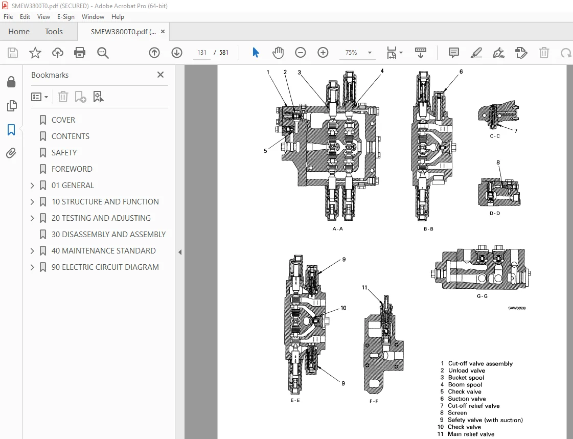
MAIN CONTROL VALVE 130
WORK EQUIPMENT LINKAGE 140
BUCKET 142
BUCKET POSITIONER AND BOOM KICK-OUT 143
AIR CONDITIONER 149
ENGINE STARTING CIRCUIT 151
ENGINE STOP CIRCUIT 152
ENGINE STOP FUEL SOLENOID 153
ELECTRIC TRANSMISSION CONTROL 154
COMBINATION SWITCH 155
KICK-DOWN SWITCH 157
KICK-DOWN ELECTRIC CIRCUIT DIAGRAM 158
TRANSMISSION CUT-OFF SWITCH 162
TANSMISSION CUT-OFF FUNCTION 163
20 TESTING AND ADJUSTING 165
STANDARD VALUE TABLE FOR ENGINE 166
STANDARD VALUE TABLE FOR CHASSIS 167
TOOLS FOR TESTING,ADJUSTING AND TROUBLESHOOTING 173
MEASURING ENGINE SPEED 175
MEASURING EXHAUST COLOR 177
TESTING AND ADJUSTING FUEL INJECTION TIMING 178
MEASURING ENGINE OIL PRESSURE 180
TESTING AND ADJUSTING AIR CONDITIONER COMPRESSOR BELT TENSION 181
MEASURING TORQUE CONVERTER,TRANSMISSION,PARKING BRAKE OIL PRESSURE 182
PROCEDURE FOR MOVING MACHINE WHEN TRANSMISSION VALVE FAILS 184
TESTING WHEEL BRAKE PERFORMANCE 185
TESTING DROP IN WHEEL BRAKE OIL PRESSURE 186
MEASURING CLEARANCE BETWEEN TIRE AND WHEEL 187
MEASURING WHEEL BRAKE DISC WEAR 188
BLEEDING AIR FROM WHEEL BRAKE CIRCUIT 189
TESTING AND ADJUSTING ACCUMULATOR CHARGE CUT-IN AND CUT-OUT PRESSURE 190
MEASURING PARKING BRAKE PERFORMANCE 192
TESTING WEAR OF PARKING BRAKE DISC 193
MEASURING WORK EQUIPMENT HYDRAULIC PRESSURE 194
BLEEDING AIR FROM WORK EQUIPMENT CIRCUIT 196
ADJUSTING WORK EQUIPMENT LEVER LINKAGE 197
TESTING AND ADJUSTING OF BUCKET PROXIMITY SWITCH 200
TESTING AND ADJUSTING OF BOOM PROXIMITY SWITCH 201
TESTING AND ADJUSTING STEERING CONTROL 203
TROUBLESHOOTING 204
POINTS TO REMEMBER WHEN TROUBLESHOOTING 205
SEQUENCE OF EVENTS IN TROUBLESHOOTING 206
POINTS TO REMEMBER WHEN CARRYING OUT MAINTENANCE 207
HANDLING CONNECTORS 214
CHECKS BEFORE TROUBLESHOOTING 215
METHOD OF USING TROUBLESHOOTING CHARTS 216
CONNECTOR TYPES AND MOUNTING LOCATIONS 224
CONNECTOR PIN ARRANGEMENT DIAGRAM 226
CONNECTION TABLE FOR CONNECTOR PIN NUMBERS 230
TROUBLESHOOTING OF ENGINE SYSTEM(S MODE) 238
TROUBLESHOOTING OF ELECTRICAL SYSTEM(E MODE) 257
TROUBLESHOOTING OF HYDRAULIC AND MECHANICAL SYSTEM(CHASSIS RELATED)(T MODE) 289
30 DISASSEMBLY AND ASSEMBLY 312
40 MAINTENANCE STANDARD 535
ENGINE MOUNT,TRANSMISSION MOUNT 536
TORQUE CONVERTER CHARGING PUMP 537
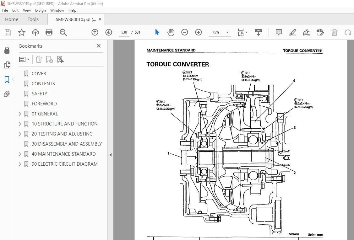
TORQUE CONVERTER 538
TRANSMISSION 540
TRANSMISSION CONTROL VALVE 547
MODULATION VALVE ASSEMBLY 551
ACCUMULATOR VALVE 552
DRIVE SHAFT 553
DIFFERENTIAL 554
FINAL DRIVE 557
AXLE MOUNT 559
CENTER HINGE PIN 560
STEERING COLUMN 562
STEERING VALVE 563
STEERING CYLINDER MOUNT 564
BRAKE 565
BRAKE VALVE 566
PARKING BRAKE 567
HYDRAULIC PUMP 568
MAIN CONTROL VALVE 569
HYDRAULIC CYLINDER 573
WORK EQUIPMENT LINKAGE 574
BUCKET 576
BUCKET POSITIONER AND BOOM KICK-OUT 577
90 ELECTRIC CIRCUIT DIAGRAM 578
WA 380-3 WIRING DIAGRAM 579
WA AIR CONDITIONER WIRING DIAGRAM(1/2) 580
WA AIR CONDITIONER WIRING DIAGRAM(2/2) 580
DESCRIPTION:
Komatsu WA380-3 Wheel Loader Shop Manual SMEW3800T0 – PDF DOWNLOAD
SERIAL NUMBER
WA380-16001 and up
GENERAL PRECAUTIONS :
Mistakes in operation are extremely dangerous. Read the OPERATION & MAINTENANCE MANUAL carefully BEFORE operating the machine.
PREPARATIONS FOR WORK:
PRECAUTIONS DURING WORK :
IMAGES PREVIEW OF THE MANUAL:
S.V 28/12/24


