Komatsu WA470-6, WA480-6 Wheel Loader Service Repair Manual PDF
$38.95
Komatsu WA470-6 WA480-6 Wheel Loader Shop Manual SEN00783-10 – PDF DOWNLOAD
Description
Komatsu WA470-6 WA480-6 Wheel Loader Shop Manual SEN00783-10 – PDF DOWNLOAD
FILE DETAILS:
Komatsu WA470-6 WA480-6 Wheel Loader Shop Manual SEN00783-10 – PDF DOWNLOAD
Language : English
Pages : 1769
Downloadable : Yes
File Type : PDF
DESCRIPTION:
Komatsu WA470-6 WA480-6 Wheel Loader Shop Manual SEN00783-10 – PDF DOWNLOAD
WA480-85001 to 90000
How to read the shop manual 1
1. Composition of shop manual
This shop manual contains the necessary technical information for services performed in a workshop.
For ease of understanding, the manual is divided into the following sections.
00. Index and foreword
This section explains the shop manuals list, table of contents, safety, and basic information.
01. Specification
This section explains the specifications of the machine.
10. Structure, function and maintenance standard
This section explains the structure, function, and maintenance standard values of each component.
The structure and function sub-section explains the structure and function of each component. It
serves not only to give an understanding of the structure, but also serves as reference material for
troubleshooting. The maintenance standard sub-section explains the criteria and remedies for disassembly
and service.
20. Standard value table
This section explains the standard values for new machine and judgement criteria for testing,
adjusting, and troubleshooting. This standard value table is used to check the standard values in
testing and adjusting and to judge parts in troubleshooting.
30. Testing and adjusting
This section explains measuring instruments and measuring methods for testing and adjusting, and
method of adjusting each part. The standard values and judgement criteria for testing and adjusting
are explained in Testing and adjusting.
40. Troubleshooting
This section explains how to find out failed parts and how to repair them. The troubleshooting is
divided by failure modes. The “S mode” of the troubleshooting related to the engine may be also
explained in the Chassis volume and Engine volume. In this case, see the Chassis volume.
50. Disassembly and assembly
This section explains the special tools and procedures for removing, installing, disassembling, and
assembling each component, as well as precautions for them. In addition, tightening torque and
quantity and weight of coating material, oil, grease, and coolant necessary for the work are also
explained.
90. Diagrams and drawings (chassis volume)/Repair and replacement of parts (engine volume)
q Chassis volume
This section gives hydraulic circuit diagrams and electrical circuit diagrams.
q Engine volume
This section explains the method of reproducing, repairing, and replacing parts.
TABLE OF CONTENTS:
Komatsu WA470-6 WA480-6 Wheel Loader Shop Manual SEN00783-10 – PDF DOWNLOAD
WA480-85001 to 90000
Cover 1
00 Index and foreword 0
Index 3
Composition of shop manual 4
Table of contents 6
Foreword and general information 21
Safety notice 22
How to read the shop manual 27
Explanation of terms for maintenance standard 29
Handling of electric equipment and hydraulic component 31
Handling of connectors newly used for engines 40
How to read electric wire code 43
Precautions when carrying out operation 46
Method of disassembling and connecting push-pull type coupler 49
Standard tightening torque table 52
Conversion table 56
01 Specification 0
Specification and technical data 63
Specification dimension drawing 65
Specifications 66
Weight table 70
Table of fuel, coolant and lubricants 72
10 Structure, function and maintenance standard 0
Engine and cooling system 75
Engine mount and transmission mount 76
Cooling system 77
Cooling fan pump 78
Cooling fan motor 86
Power train 93
Power train 95
Power train system diagram 96
Drive shaft 98
Power train piping diagram 99
Torque converter 100
Transmission 108
Flow control valve 125
Transmission control valve 126
ECMV 130
Main relief valve and torque converter relief valve 136
Axle 138
Differential 142
Limited slip differential 147
Final drive 154
Steering system 161
Steering piping diagram 162
Steering column 163
Steering pump 164
Steering valve 177
Orbit-roll valve 192
Stop valve 200
Steering relief valve 201
Steering cylinder 202
Emergency steering motor 204
Emergency steering pump 205
Joystick steering lever linkage 206
Steering electric lever 207
Joystick EPC valve 208
Brake system 211
Brake piping diagram 212
Charge valve 213
Brake valve 220
Accumulator (for brake) 225
Slack adjuster 226
Brake 228
Parking brake control 233
Parking brake 234
Parking brake solenoid valve 236
Emergency parking brake release valve 238
Undercarriage and frame 241
Axle mount and center hinge pin 242
Tires 246
Hydraulic system, Part 1 249
Hydraulic piping diagram 250
Work equipment control lever linkage 253
Hydraulic tank 256
Power train pump 258
Work equipment pump 260
Work equipment control valve 280
CLSS 291
Each function and operation of each valve 296
Hydraulic system, Part 2 311
PPC valve 312
Accumulator (for PPC circuit) 318
Accumulator (for ECSS) 319
Work equipment PPC cut-off solenoid valve 320
Work equipment 323
Work equipment linkage 324
Bucket 327
Bucket positioner and boom kick-out 328
Work equipment cylinder 334
Cab and its attachments 337
Cab 339
Air conditioner 340
Electrical system, Part 1 359
Machine monitor system 360
Machine monitor 364
Electrical system, Part 2 397
Electrical system (Transmission controller system) 398
Transmission controller 430
Electrical system (Work equipment controller system) 432
Work equipment controller 438
Electrical system, Part 3 441
Electric transmission control 444
Combination switch 446
Kickdown switch and hold switch 448
Loadmeter cancel switch and loadmeter subtotal switch 448
Multi-function knob 449
Joystick steering knob 450
KOMTRAX system 452
Engine starting circuit 454
Engine stopping circuit 456
Preheating circuit 457
Engine power mode selector circuit 458
Engine output derating function 459
Automatic warm-up function 459
Parking brake circuit 460
Sensor 462
20 Standard value table 0
Standard service value table 473
Standard value table for engine 474
Standard value table for chassis 475
30 Testing and adjusting 0
Testing and adjusting, Part 1 485
Tools for testing, adjusting, and troubleshooting 487
Testing engine speed 492
Testing exhaust gas color 494
Testing exhaust temperature 495
Adjusting valve clearance 497
Testing compression pressure 499
Testing blow-by pressure 501
Testing engine oil pressure 502
Testing EGR valve drive pressure 503
Testing intake air (boost) pressure 504
Handling fuel system equipment 505
Releasing residual pressure in fuel system 505
Testing fuel pressure 506
Testing fuel return and leak amount 507
Bleeding air from fuel circuit 510
Testing fuel circuit for leakage 513
Handling of reduced cylinder mode operation 514
Handling of no injection cranking operation 514
Handling controller voltage circuit 515
Check of muffler and muffler stack for looseness and damage 516
Check of muffler function 516
Check of installed condition of cylinder head and manifolds 517
Check of engine piping for damage and looseness 517
Testing and adjusting air conditioner compressor belt tension 518
Testing and adjusting alternator belt tension 519
Adjusting transmission speed sensor 520
Adjusting directional lever length 521
Adjusting gear shift lever length 521
Testing directional lever 522
Testing and adjusting power train oil pressure 524
Procedure for flushing torque converter and transmission hydraulic circuit 539
Method of moving machine when transmission valve is broken 540
Check of axle final drive for oil leakage 542
Check of drive shafts for looseness, play and damage 542
Testing and adjusting steering stop valve 543
Testing and adjusting steering wheel 545
Testing steering oil pressure 547
Bleeding air from steering circuit 550
Testing and adjusting, Part 2 553
Testing hydraulic drive fan 555
Bleeding air from hydraulic drive fan circuit 557
Testing brake pedal 559
Testing and adjusting brake pedal linkage 560
Testing brake performance 561
Testing and adjusting accumulator charge pressure 562
Testing wheel brake oil pressure 563
Testing wear of wheel brake disc 565
Bleeding air from wheel brake circuit 566
Releasing residual pressure in brake accumulator circuit 567
Testing parking brake performance 567
Testing parking brake oil pressure 568
Testing wear of parking brake disc 570
Manual release method for parking brake 571
Testing and adjusting work equipment control lever 572
Testing and adjusting work equipment PPC oil pressure 573
Testing and adjusting work equipment oil pressure 576
Bleeding air from work equipment circuit 580
Releasing residual pressure in work equipment circuit 581
Procedure for testing of nitrogen gas pressure and charging of nitrogen gas of ECSS (Electronically Controlled Suspension System) accumulator 582
Procedure for testing of nitrogen gas pressure and charging of nitrogen gas of brake accumulator 588
Testing and adjusting bucket positioner 593
Testing and adjusting boom kick-out 595
Checking proximity switch operation pilot lamp 596
Procedure for testing diodes 597
Preparation work for troubleshooting for electrical system 598
Starting KOMTRAX terminal operations 603
Indicator lamps of KOMTRAX terminal 608
Testing and adjusting, Part 3 613
Adjusting machine monitor 614
Adjusting replaced, reassembled or added sensor, controller, etc with machine monitor 615
Special functions of machine monitor (EMMS) 617
Pm-clinic inspection table 680
40 Troubleshooting 0
Failure code table and fuse locations 685
Failure code table 686
Fuse locations 698
General information on troubleshooting 703
Points to remember when troubleshooting 704
Sequence of events in troubleshooting 705
Testing before troubleshooting 706
Classification and procedures of troubleshooting 707
Information contained in troubleshooting table 711
Connection table for connector pin numbers 713
T- branch box and T- branch adapter table 749
Troubleshooting by failure code (Display of code), Part 1 753
Failure code [1500L0] (TORQFLOW transmission: Double meshing) 755
Failure code [15SAL1] (ECMV F clutch: When command current is OFF, fill signal is ON) 756
Failure code [15SALH] (ECMV F clutch: When command current is ON, fill signal is OFF) 758
Failure code [15SBL1] (ECMV R clutch: When command current is OFF, fill signal is ON) 760
Failure code [15SBLH] (ECMV R clutch: When command current is ON, fill signal is OFF) 762
Failure code [15SEL1] (ECMV 1st clutch: When command current is OFF, fill signal is ON) 764
Failure code [15SELH] (ECMV 1st clutch: When command current is ON, fill signal is OFF) 766
Failure code [15SFL1] (ECMV 2nd clutch: When command current is OFF, fill signal is ON) 768
Failure code [15SFLH] (ECMV 2nd clutch: When command current is ON, fill signal is OFF) 770
Failure code [15SGL1] (ECMV 3rd clutch: When command current is OFF, fill signal is ON) 772
Failure code [15SGLH] (ECMV 3rd clutch: When command current is ON, fill signal is OFF) 774
Failure code [15SHL1] (ECMV 4th clutch: When command current is OFF, fill signal is ON) 776
Failure code [15SHLH] (ECMV 4th clutch: When command current is ON, fill signal is OFF) 778
Failure code [2F00MA] (Parking brake: Malfunction) 780
Failure code [2G43ZG] (Accumulator: Low oil pressure) 782
Failure code [44K0L4] (Bucket positioner: ON/OFF signals disagree) 784
Troubleshooting by failure code (Display of code), Part 2 789
Failure code [AA1ANX] (Air cleaner: Clogging) 792
Failure code [AB00L6] (Alternator: Signal disagrees with operating state of engine) 794
Failure code [AB00MA] (Alternator: Malfunction) 796
Failure code [B@BAZG] (Rotation derating by low engine oil pressure) 798
Failure code [B@BAZK] (Engine oil: Low level) 801
Failure code [B@BCNS] (Coolant: Overheating) 802
Failure code [B@BCZK] (Coolant: Low level) 804
Failure code [b@CENS] (Torque converter oil: Overheating) 806
Failure code [B@CENS] (Torque converter oil: Overheating) 808
Failure code [B@HANS] (Hydraulic oil: Overheating) 810
Failure code [CA111] (Abnormality in engine controller) 812
Failure code [CA115] (Engine Ne or Bkup speed sensor error) 815
Failure code [CA122] (Charge pressure sensor high error) 816
Failure code [CA123] (Charge pressure sensor low error) 818
Failure code [CA131] (Throttle sensor high error) 820
Failure code [CA132] (Throttle sensor low error) 822
Failure code [CA135] (Engine oil pressure sensor high error) 824
Failure code [CA141] (Engine oil pressure sensor low error) 826
Failure code [CA144] (Coolant sensor high error) 828
Failure code [CA145] (Coolant sensor low error) 830
Failure code [CA153] (Charge temperature sensor high error) 832
Failure code [CA154] (Charge temperature sensor low error) 834
Failure code [CA187] (Sensor power supply 2 low error) 836
Failure code [CA221] (Atmospheric pressure sensor high error) 837
Failure code [CA222] (Atmospheric pressure sensor low error) 839
Failure code [CA227] (Sensor power supply 2 high error) 840
Failure code [CA234] (Engine overspeed) 842
Failure code [CA238] (Ne speed sensor power supply error) 844
Troubleshooting by failure code (Display of code), Part 3 847
Failure code [CA263] (Fuel temperature sensor high error) 850
Failure code [CA265] (Fuel temperature sensor low error) 852
Failure code [CA271] (PCV1 Short circuit) 854
Failure code [CA272] (PCV1 Disconnection) 856
Failure code [CA273] (PCV2 Short circuit) 858
Failure code [CA274] (PCV2 Disconnection) 860
Failure code [CA322] (Injector #1 open/short error) 862
Failure code [CA323] (Injector #5 open/short error) 864
Failure code [CA324] (Injector #3 open/short error) 866
Failure code [CA325] (Injector #6 open/short error) 868
Failure code [CA331] (Injector #2 open/short error) 870
Failure code [CA332] (Injector #4 open/short error) 872
Failure code [CA342] (Calibration code inconsistency) 874
Failure code [CA351] (Injectors drive circuit error) 875
Failure code [CA352] (Sensor power supply 1 low error) 877
Failure code [CA386] (Sensor power supply 1 high error) 878
Failure code [CA431] (Idle validation switch error) 880
Failure code [CA432] (Idle validation action error) 882
Failure code [CA441] (Battery voltage low error) 884
Failure code [CA442] (Battery voltage high error) 887
Failure code [CA449] Common rail pressure high error 2 889
Failure code [CA451] (Common rail pressure sensor high error) 890
Failure code [CA452] (Common rail pressure sensor low error) 892
Failure code [CA553] (Common rail pressure high error 1) 893
Failure code [CA554] (Common rail pressure sensor in-range error) 894
Failure code [CA559] (Supply pump pressure very low error) 895
Failure code [CA689] (Engine Ne speed sensor error) 899
Failure code [CA731] (Engine Bkup speed sensor phase error) 901
Failure code [CA757] (All continuous data lost error) 901
Failure code [CA778] (Engine Bkup speed sensor error) 902
Failure code [CA1228] (EGR valve servo error 1) 904
Failure code [CA1625] (EGR valve servo error 2) 905
Failure code [CA1633] (KOMNET datalink timeout error) 906
Failure code [CA2185] (Throttle sensor supply voltage high error) 908
Failure code [CA2186] (Throttle sensor power supply low error) 909
Troubleshooting by failure code (Display of code), Part 4 911
Failure code [CA2249] (Supply pump pressure very low error 2) 913
Failure code [CA2271] (EGR valve lift sensor high error) 914
Failure code [CA2272] (EGR valve lift sensor low error) 916
Failure code [CA2351] (EGR valve solenoid operation short circuit) 917
Failure code [CA2352] (EGR valve solenoid operation disconnect) 919
Failure code [CA2555] (Intake heater relay disconnection error) 920
Failure code [CA2556] (Intake heater relay short circuit error) 922
Failure code [D150KA] (Emergency steering relay: Disconnection) 924
Failure code [D150KB] (Emergency steering relay: Short circuit) 926
Failure code [D150KY] (Emergency steering relay: Short circuit with power supply line) 928
Failure code [D160KA] (Backup lamp relay: Disconnection) 930
Failure code [D160KB] (Backup lamp relay: Short circuit) 932
Failure code [D191KA] (Joystick steering neutral safety relay: Disconnection) 934
Failure code [D191KB] (Joystick steering neutral safety relay: Short circuit) 936
Failure code [D191KY] (Joystick steering neutral safety relay: Short circuit with power supply line) 938
Failure code [D192KA] (ECSS solenoid: Disconnection) 940
Failure code [D192KB] (ECSS solenoid: Short circuit) 941
Failure code [D192KY] (ECSS solenoid: Short circuit with power supply line) 942
Failure code [D193KA] (Joystick steering solenoid cut-off relay: Disconnection) 944
Failure code [D193KB] (Joystick steering solenoid cut-off relay: Short circuit) 946
Failure code [D193KY] (Joystick steering solenoid cut-off relay: Short circuit with power supply line) 948
Failure code [D5ZHKA] (Terminal C signal: Disconnection) 951
Failure code [D5ZHKB] (Terminal C signal: Short circuit) 955
Failure code [D5ZHKZ] (Terminal C signal: Disconnection or short circuit) 958
Failure code [D5ZHL6] (Terminal C signal: Signal does not match engine running or stopped state) 963
Failure code [DA80L4] (Auto grease controller: ON/OFF signals disagree) 966
Failure code [DAF3KK] (Machine monitor: Low source voltage (input)) 968
Failure code [DAF5KP] (Machine monitor: Low output voltage) 970
Failure code [DAFRKR] (CAN communication with machine monitor: Defective communication (Abnormality in target component system)) 974
Troubleshooting by failure code (Display of code), Part 5 977
Failure code [DAQ0KK] (Transmission controller: Low source voltage) 979
Failure code [DAQ0KT] (Transmission controller: Abnormality in controller) 981
Failure code [DAQ1KA] (Terminal ACC input: Disconnection) 983
Failure code [DAQ2KK] (Transmission controller load power supply line: Low source voltage (input)) 986
Failure code [DAQ9KQ] (Transmission controller model selection: Disagreement of model selection signals) 988
Failure code [DAQRKR] (CAN communication with transmission controller: Defective communication (Abnormality in target component system)) 989
Failure code [DAQRMA] (Transmission controller option setting: Malfunction) 991
Failure code [DB2RKR] (CAN communication with engine controller: Defective communication (Abnormality in target component system) 992
Failure code [DB90KK] Work equipment controller: Low source voltage (input) 994
Failure code [DB90KT] Work equipment controller: Abnormality in controller 996
Failure code [DB92KK] Work equipment controller load power supply line: Low source voltage (input) 997
Failure code [DB95KX] Work equipment controller power supply output: Out of input signal range 999
Failure code [DB99KQ] (Work equipment controller model selection: Disagreement in model selection signals) 1002
Failure code [DB9RKR] CAN communication with work equipment controller: Defective communication (Abnormality in target component system) 1003
Failure code [DB9RMA] (Work equipment controller option setting: Malfunction) 1005
Failure code [DB9RMC] (CAN communication with transmission controller: Defective operation) 1006
Failure code [DD15LD] ■ switch (Panel switch 1): Switch is kept pressed for long time 1010
Failure code [DD16LD] ◇ switch (Panel switch 2): Switch is kept pressed for long time 1012
Failure code [DD17LD] < switch (Panel switch 3): Switch is kept pressed for long time 1014
Failure code [DD18LD] > switch (Panel switch 4): Switch is kept pressed for long time 1016
Failure code [DD1ALD] Remote positioner raise/lower set switch (raise): Switch is kept pressed for long time 1018
Failure code [DD1BLD] Remote positioner raise/lower set switch (lower): Switch is kept pressed for long time 1020
Failure code [DD1CLD] Load meter subtotal switch: Switch is kept pressed for long time 1022
Failure code [DD1FLD] Load meter mode selector switch (A/B): Switch is kept pressed for long time 1024
Failure code [DD1GLD] Load meter mode selector switch (+/–): Switch is kept pressed for long time 1026
Failure code [DD1HLD] (Load meter display selector switch: Switch is kept pressed for long time) 1028
Failure code [DD1NLD] (Fan reverse switch: Switch is kept pressed for long time) 1030
Failure code [DD1NL4] (Fan automatic reverse switch: Switch is kept pressed for long time) 1032
Failure code [DDB6L4] (Parking brake switch (Neutralizer): ON/OFF signals disagree) 1034
Failure code [DDD1LD] (Remote positioner bucket angle set switch: Switch is kept pressed for long time) 1038
Troubleshooting by failure code (Display of code), Part 6 1041
Failure code [DDE5MA] (Emergency steering drive switch: Malfunction) 1044
Failure code [DDK3KA] (Right FNR switch: Disconnection) 1046
Failure code [DDK4KA] (Joystick steering FNR switch: Disconnection) 1049
Failure code [DDK5L4] (Joystick steering shift-up/down switch: ON/OFF signals disagree) 1052
Failure code [DDK6KA] (FNR lever switch: Disconnection) 1054
Failure code [DDK6KB] (FNR lever switch: Short circuit) 1058
Failure code [DDS5KA] (Steering pressure switch: Disconnected) 1060
Failure code [DDS5KB] (Steering pressure switch: Short circuit) 1062
Failure code [DDS5L6] (Steering: Low oil pressure) 1064
Failure code [DDT0L4] (Shift mode selector switch: ON/OFF signals disagree) 1066
Failure code [DDT4LD] (Transmission cut-off set switch: Switch is kept pressed for long time) 1068
Failure code [DDW9LD] (Kick-down switch: Switch is kept pressed for long time) 1070
Failure code [DDWLLD] (Hold switch: Switch is kept pressed for long time) 1072
Failure code [DDY0LD] (Load meter cancel switch: Switch is kept pressed for long time) 1074
Failure code [DF10KA] (Transmission shift lever switch: Disconnected) 1076
Failure code [DF10KB] (Transmission shift lever switch: Short circuit) 1080
Failure code [DGF1KA] (Transmission oil temperature sensor: Disconnected) 1082
Failure code [DGF1KB] (Transmission oil temperature sensor: Short circuit) 1084
Failure code [DGH2KX] (Hydraulic oil temperature sensor: Out of input signal range) 1086
Failure code [DGR2KA] (Rear brake oil temperature sensor: Disconnected) 1088
Failure code [DGR2KX] (Rear brake oil temperature sensor: Out of input signal range) 1090
Failure code [DGT1KX] (Torque converter oil temperature sensor: Out of input signal range) 1092
Failure code [DH21KA] (Loader pump pressure sensor: Disconnection) 1094
Failure code [DH21KB] (Loader pump pressure sensor: Power supply line short) 1096
Troubleshooting by failure code (Display of code), Part 7 1099
Failure code [DHPCKX] (Lift arm cylinder bottom pressure sensor: Out of input signal range) 1102
Failure code [DHPDKX] (Lift arm cylinder head pressure sensor: Out of input signal range) 1104
Failure code [DHT1KX] (Transmission cut-off pressure sensor: Out of input signal range) 1106
Failure code [DHT8KA] (Steering pump pressure sensor: Disconnection) 1108
Failure code [DHT8KB] (Steering pump pressure sensor: Short circuit) 1110
Failure code [DK59KA] (Lift arm EPC lever potentiometer (Main): Disconnection) 1112
Failure code [DK59KY] (Lift arm EPC lever potentiometer (Main): Short circuit with power supply line) 1115
Failure code [DK59L8] (Lift arm EPC lever potentiometer (Main): Analog signals disagree) 1118
Failure code [DK5AKA] (Lift arm EPC lever potentiometer (Sub): Disconnection) 1121
Failure code [DK5AKY] (Lift arm EPC lever potentiometer (Sub): Short circuit with power supply line) 1124
Failure code [DK5BKA] (Bucket EPC lever potentiometer (Main): Disconnection) 1127
Failure code [DK5BKY] (Bucket EPC lever potentiometer (Main): Short circuit with power supply line) 1130
Failure code [DK5BL8] (Bucket EPC lever potentiometer (Main): Analog signals disagree) 1133
Failure code [DK5CKA] (Bucket EPC lever potentiometer (Sub): Disconnection) 1136
Failure code [DK5CKY] (Bucket EPC lever potentiometer (Sub): Short circuit with power supply line) 1139
Troubleshooting by failure code (Display of code), Part 8 1143
Failure code [DK5FKA] (Joystick steering EPC lever potentiometer (Main): Disconnection) 1145
Failure code [DK5FKY] (Joystick steering EPC lever potentiometer (Main): Short circuit with power supply line) 1148
Failure code [DK5GKA] (Joystick steering EPC lever potentiometer (Sub): Disconnection) 1150
Failure code [DK5GKY] (Joystick steering EPC lever potentiometer (Sub): Short circuit with power supply line) 1153
Failure code [DK5FL8] (Joystick steering EPC lever potentiometer (Main): Analog signals disagree) 1155
Failure code [DKA0KA] (Lift arm angle sensor: Disconnection) 1158
Failure code [DKA0KX] (Lift arm angle sensor: Out of input signal range) 1160
Failure code [DKA0KY] (Lift arm angle sensor: Short circuit with power supply line) 1162
Failure code [DKA0L0] (Lift arm angle sensor: Double meshing) 1164
Failure code [DLT3KA] (Transmission output shaft speed sensor: Disconnection) 1166
Failure code [DLT3LC] (Transmission output shaft speed sensor: Out of input signal range) 1168
Failure code [DT20KB] (Transmission cut-off indicator lamp: Short circuit) 1170
Failure code [DUM1KB] (Remote positioner raise set indicator lamp: Short circuit) 1172
Failure code [DUM2KB] (Remote positioner lower set indicator lamp: Short circuit) 1174
Failure code [DV00KB] (Alarm buzzer: Short circuit) 1176
Failure code [DW4PKA] (Lift arm raise EPC solenoid: Disconnection) 1178
Failure code [DW4PKB] (Lift arm raise EPC solenoid: Short circuit) 1180
Failure code [DW4PKY] (Lift arm raise EPC solenoid: Short circuit with power supply line) 1182
Failure code [DW4QKA] (Lift arm lower EPC solenoid: Disconnection) 1184
Failure code [DW4QKB] (Lift arm lower EPC solenoid: Short circuit) 1185
Failure code [DW4QKY] (Lift arm lower EPC solenoid: Short circuit with power supply line) 1186
Failure code [DW4RKA] (Bucket tilt EPC solenoid: Disconnection) 1188
Failure code [DW4RKB] (Bucket tilt EPC solenoid: Short circuit) 1189
Failure code [DW4RKY] (Bucket tilt EPC solenoid: Short circuit with power supply line) 1190
Troubleshooting by failure code (Display of code), Part 9 1193
Failure code [DW4SKA] (Bucket dump EPC solenoid: Disconnection) 1195
Failure code [DW4SKB] (Bucket dump EPC solenoid: Short circuit) 1196
Failure code [DW4SKY] (Bucket dump EPC solenoid: Short circuit with power supply line) 1197
Failure code [DW7BKA] (Fan reverse solenoid: Disconnection) 1199
Failure code [DW7BKB] (Fan reverse solenoid: Short circuit) 1200
Failure code [DW7BKY] (Fan reverse solenoid: Short circuit with power supply line) 1201
Failure code [DW7DKA] (Hydraulic drive fan neutral solenoid: Disconnection) 1203
Failure code [DW7DKB] (Hydraulic drive fan neutral solenoid: Short circuit) 1204
Failure code [DW7DKY] (Hydraulic drive fan neutral solenoid: Short circuit with power supply line) 1205
Failure code [DWM1KA] (Work equipment neutral lock solenoid: Disconnection) 1206
Failure code [DWM1KB] (Work equipment neutral lock solenoid: Short circuit) 1208
Failure code [DWM1KY] (Work equipment neutral lock solenoid: Short circuit with power supply line) 1210
Failure code [DWN6KA] (Lift arm raise magnet detent solenoid: Disconnection) 1212
Failure code [DWN6KB] (Lift arm raise magnet detent solenoid: Short circuit) 1214
Failure code [DWN6KY] (Lift arm raise magnet detent solenoid: Short circuit with power supply line) 1216
Failure code [DWN7KA] (Lift arm float magnet detent solenoid: Disconnection) 1218
Failure code [DWN7KB] (Lift arm float magnet detent solenoid: Short circuit) 1220
Failure code [DWN7KY] (Lift arm float magnet detent solenoid: Short circuit with power supply line) 1222
Failure code [DWN8KA] (Bucket tilt magnet detent solenoid: Disconnection) 1224
Failure code [DWN8KB] (Bucket tilt magnet detent solenoid: Short circuit) 1226
Failure code [DWN8KY] (Bucket tilt magnet detent solenoid: Shorted with the power source) 1228
Failure code [DX16KA] (Fan pump EPC solenoid: Disconnection) 1230
Failure code [DX16KB] (Fan pump EPC solenoid: Short circuit) 1231
Failure code [DX16KY] (Fan pump EPC solenoid: Short circuit with power supply line) 1232
Failure code [DXH1KA] (Lockup ECMV solenoid: Disconnection) 1234
Failure code [DXH1KB] (Lockup ECMV solenoid: Short circuit) 1236
Failure code [DXH1KY] (Lockup ECMV solenoid: Short circuit with power supply line) 1238
Failure code [DXH4KA] (1st clutch ECMV solenoid: Disconnection) 1240
Failure code [DXH4KB] (1st clutch ECMV solenoid: Short circuit) 1242
Failure code [DXH4KY] (1st clutch ECMV solenoid: Short circuit with power supply line) 1244
Troubleshooting by failure code (Display of code), Part 10 1247
Failure code [DXH5KA] (2nd clutch ECMV solenoid: Disconnection) 1250
Failure code [DXH5KB] (2nd clutch ECMV solenoid: Short circuit) 1252
Failure code [DXH5KY] (2nd clutch ECMV solenoid: Short circuit with power supply line) 1254
Failure code [DXH6KA] (3rd clutch ECMV solenoid: Disconnection) 1256
Failure code [DXH6KB] (3rd clutch ECMV solenoid: Short circuit) 1258
Failure code [DXH6KY] (3rd clutch ECMV solenoid: Short circuit with power supply line) 1260
Failure code [DXH7KA] (R clutch ECMV solenoid: Disconnection) 1262
Failure code [DXH7KB] (R clutch ECMV solenoid: Short circuit) 1264
Failure code [DXH7KY] (R clutch ECMV solenoid: Short circuit with power supply line) 1266
Failure code [DXH8KA] (F clutch ECMV solenoid: Disconnection) 1268
Failure code [DXH8KB] (F clutch ECMV solenoid: Short circuit) 1270
Failure code [DXH8KY] (F clutch ECMV solenoid: Short circuit with power supply line) 1272
Failure code [DXHHKA] (4th clutch ECMV solenoid: Disconnection) 1274
Failure code [DXHHKB] (4th clutch ECMV solenoid: Short circuit) 1276
Failure code [DXHHKY] (4th clutch ECMV solenoid: Short circuit with power supply line) 1278
Failure code [DXHLKA] (Joystick steering right EPC solenoid: Disconnection) 1280
Failure code [DXHLKB] (Joystick steering right EPC solenoid: Short circuit) 1282
Failure code [DXHLKY] (Joystick steering right EPC solenoid: Short circuit with power supply line) 1284
Failure code [DXHMKA] (Joystick steering left EPC solenoid: Disconnection) 1286
Failure code [DXHMKB] (Joystick steering left EPC solenoid: Short circuit) 1288
Failure code [DXHMKY] (Joystick steering left EPC solenoid: Short circuit with power supply line) 1290
Failure code [DY30MA] Motor-driven emergency steering pump failure (During operation of machine) 1292
Failure code [DY30MC] Motor-driven emergency steering pump failure (Malfunction in manual mode) 1295
Failure code [DY30ME] Emergency steering: Operating for more than 1 minute 1298
Troubleshooting of electrical system (E-mode) 1303
Installing positions of fuses 1305
Information in troubleshooting table 1308
E-1 Engine does not start 1310
E-2 Wiper does not operate 1316
E-3 Windshield washer does not operate 1320
E-4 Headlamp, clearance lamp, tail lamp, and license lamp do not light up or go off 1323
E-5 Working lamp does not light up or go off 1331
E-6 Turn signal lamp and hazard lamp do not light up or go off 1336
E-7 Brake lamp does not light or it keeps lighting up 1342
E-8 Backup lamp does not light or it keeps lighting up 1344
E-9 Backup buzzer does not sound or it keeps sounding 1346
E-10 Horn does not sound or it keeps sounding 1348
E-11 Alarm buzzer does not sound or it keeps sounding 1350
E-12 Air conditioner does not operate or stop 1352
E-13 The KOMTRAX system does not work properly 1355
E-14 When kick-down switch is turned ON, kick-down operation does not start 1358
E-15 When hold switch is pressed, holding operation does not start 1360
E-16 Transmission is kept in neutral, or brake drags when directional lever is operated while parking brake is applied 1362
E-17 Transmission cut-off mode cannot be set or reset 1364
E-18 Transmission cut-off set cannot be reset 1366
E-19 FNR switch mode cannot be set or reset 1368
E-20 Fan reverse function cannot be used or reset 1370
E-21 Discharge from loader pump does not rise from minimum level 1372
E-22 ECSS function cannot be used or reset 1374
E-23 When parking brake is turned ON, parking brake indicator lamp does not light up 1376
E-24 When emergency brake operates, brake oil pressure caution lamp does not operate 1380
E-25 Air cleaner clogging indicator lamp does not light up 1382
E-26 Radiator coolant level caution lamp does not light up 1384
E-27 Hydraulic oil temperature gauge does not rise and hydraulic oil temperature caution lamp does not light up 1385
E-28 Torque converter oil temperature gauge does not rise and torque converter oil temperature caution lamp does not light up 1386
E-29 Steering oil pressure caution lamp does not light up 1388
E-30 Abnormality in ■ switch (panel switch 1) input 1390
E-31 Abnormality in ◇ switch (panel switch 2) input 1392
E-32 Abnormality in < switch (panel switch 3) input 1394
E-33 Abnormality in > switch (panel switch 4) input 1396
Troubleshooting of hydraulic and mechanical system (H-mode) 1399
Method of using troubleshooting chart 1401
Table of failure modes and causes 1404
H-1 The machine does not start 1408
H-2 Torque converter lockup is not switched off (engine stalls) [Machine with lockup clutch (if equipped)] 1410
H-3 Torque converter lockup is not switched on [Machine with lockup clutch (if equipped)] 1411
H-4 The travel speed is slow, the thrusting force is weak, the uphill traveling power is weak, and the gear is not shifted 1412
H-5 Shocks are large at the times of starting and shifting gear 1414
H-6 Time lag is large at the times of starting and shifting gear 1416
H-7 The torque converter oil temperature is high 1418
H-8 Steering does not turn 1419
H-9 Steering does not turn [Machine with joystick steering (if equipped)] 1420
H-10 Steering response is poor 1421
H-11 Turning, response of steering is poor [machine with joystick steering (if equipped)] 1422
H-12 Steering is heavy 1423
H-13 When machine turns, it shakes or makes large shocks 1424
H-14 When machine turns, it shakes or makes large shocks [machine with joystick steering (if equipped)] 1425
H-15 The wheel brake does not work or does not work well 1426
H-16 The wheel brake is not released or it drags 1427
H-17 The parking brake does not work or does not work well 1428
H-18 The parking brake is not released or it drags (including emergency release system) 1429
H-19 Lift arm does not rise 1430
H-20 Lift arm speed is low or rising force of lift arm is insufficient 1431
H-21 When rising, the lift arm comes to move slowly at specific height 1432
H-22 The lift arm cylinder cannot hold down the bucket (Bucket floats) 1432
H-23 Hydraulic drifts of the lift arm is large 1432
H-24 The lift arm wobbles during operation 1432
H-25 Bucket does not tilt back 1433
H-26 Bucket speed is low or tilting back force is insufficient 1434
H-27 The bucket comes to operate slowly in the midst of tilting-back 1435
H-28 The bucket cylinder cannot hold down the bucket 1435
H-29 Hydraulic drifts of the bucket is large 1435
H-30 The bucket wobbles during travel with cargo (The work equipment valve is set to “HOLD”) 1435
H-31 Lift arm and bucket control levers do not move smoothly and are heavy 1436
H-32 During operation of the machine, engine speed lowers remarkably or engine stalls 1437
H-33 Large shock is made when work equipment starts and stops 1437
H-34 When work equipment circuit is relieved singly, other work equipment moves 1437
H-35 ECSS does not operate, and pitching, bouncing occur 1438
Troubleshooting of engine (S-mode) 1441
Method of using troubleshooting chart 1443
S-1 Starting performance is poor 1446
S-2 Engine does not start 1448
S-3 Engine does not pick up smoothly 1452
S-4 Engine stops during operation 1453
S-5 Engine does not rotate smoothly 1454
S-6 Engine lacks output (or lacks power) 1455
S-7 Exhaust smoke is black (Incomplete combustion) 1456
S-8 Oil is consumed much (or exhaust gas color is blue) 1457
S-9 Engine oil becomes contaminated quickly 1458
S-10 Fuel consumption is excessive 1459
S-11 Coolant contains oil (blows back or reduces) 1460
S-12 Oil pressure drops 1461
S-13 Oil level rises (Water, fuel in oil) 1462
S-14 Coolant temperature rises too high (Overheating) 1464
S-15 Abnormal noise is made 1465
S-16 Vibration is excessive 1466
50 Disassembly and assembly 0
General information on disassembly and assembly 1469
How to read this manual 1470
Coating materials list 1472
Special tools list 1475
Sketches of special tools 1479
Engine and cooling system 1493
Removal and installation of engine assembly 1494
Removal and installation of hood 1498
Removal and installation of radiator assembly 1501
Removal and installation of aftercooler assembly 1504
Removal and installation of oil cooler assembly 1506
Removal and installation of cooling fan and drive motor assembly 1508
Removal and installation of fuel supply pump assembly 1512
Removal and installation of fuel injector assembly 1518
Removal and installation of cylinder head assembly 1524
Removal and installation of engine front oil seal 1532
Removal and Installation of engine rear oil seal 1535
Removal and installation of fuel tank assembly 1540
Power train, Part 1 1545
Removal and installation of torque converter and transmission assembly 1546
Disassembly and assembly of torque converter assembly (Standard specification) 1552
Disassembly and assembly of torque converter assembly (Lockup specification) 1556
Disassembly and assembly of transmission assembly 1563
Disassembly and assembly of transmission clutch pack assembly 1577
Disassembly and assembly of parking brake assembly 1594
Power train, Part 2 1603
Removal and installation of front axle assembly 1604
Removal and installation of rear axle assembly 1606
Disassembly and assembly of axle housing assembly 1612
Disassembly and assembly of differential assembly 1621
Undercarriage and frame 1643
Removal and installation of center hinge pin 1644
Removal and installation of counterweight 1652
Hydraulic system 1655
Removal and installation of steering demand valve assembly 1656
Removal and installation of work equipment valve assembly 1659
Removal and installation of brake charge valve assembly 1662
Removal and installation of hydraulic tank assembly 1663
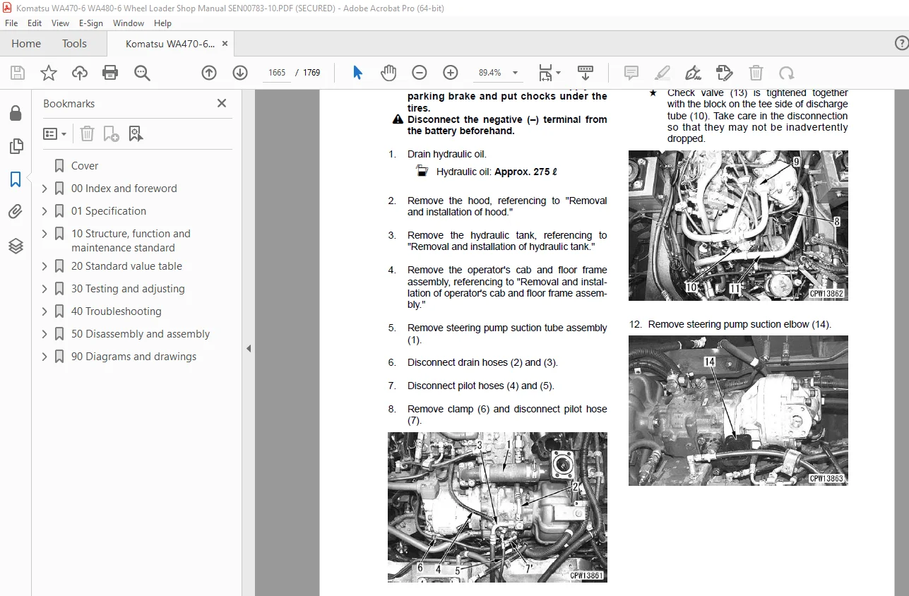
Removal and installation of steering and power train pump assembly 1665
Removal and installation of work equipment and cooling fan pump assembly 1667
Work equipment 1671
Removal and installation of work equipment assembly 1672
Cab and its attachments 1677
Removal and installation of operator’s cab and floor frame assembly 1678
Removal and installation of operator’s cab glass (stuck glass) 1682
Disassembly and assembly of operator’s seat assembly (Standard specification) 1690
Disassembly and assembly of operator’s seat assembly (Manufactured by GRAMMER) 1699
Electrical system 1733
Removal and installation of air conditioner unit assembly 1734
Removal and installation of engine controller assembly 1738
Removal and installation of transmission controller assembly 1739
Removal and installation of KOMTRAX controller assembly 1740
90 Diagrams and drawings 0
Hydraulic diagrams and drawings 1743
Hydraulic diagrams and drawings 1744
Power train hydraulic circuit diagram 1744
Hydraulic circuit diagram 1747
Electrical diagrams and drawings 1750
Electrical circuit diagram (1/14) 1752
Electrical circuit diagram (2/14) 1753
Electrical circuit diagram (3/14) 1754
Electrical circuit diagram (4/14) 1755
Electrical circuit diagram (5/14) 1756
Electrical circuit diagram (6/14) 1757
Electrical circuit diagram (7/14) 1758
Electrical circuit diagram (8/14) 1759
Electrical circuit diagram (9/14) 1760
Electrical circuit diagram (10/14) 1761
Electrical circuit diagram (11/14) 1762
Electrical circuit diagram (12/14) 1763
Electrical circuit diagram (13/14) 1764
Electrical circuit diagram (14/14) 1765
Work equipment controller system electrical circuit diagram 1766
Connector arrangement diagram 1767
IMAGES PREVIEW OF THE MANUAL:
S.V 17/12/24


