
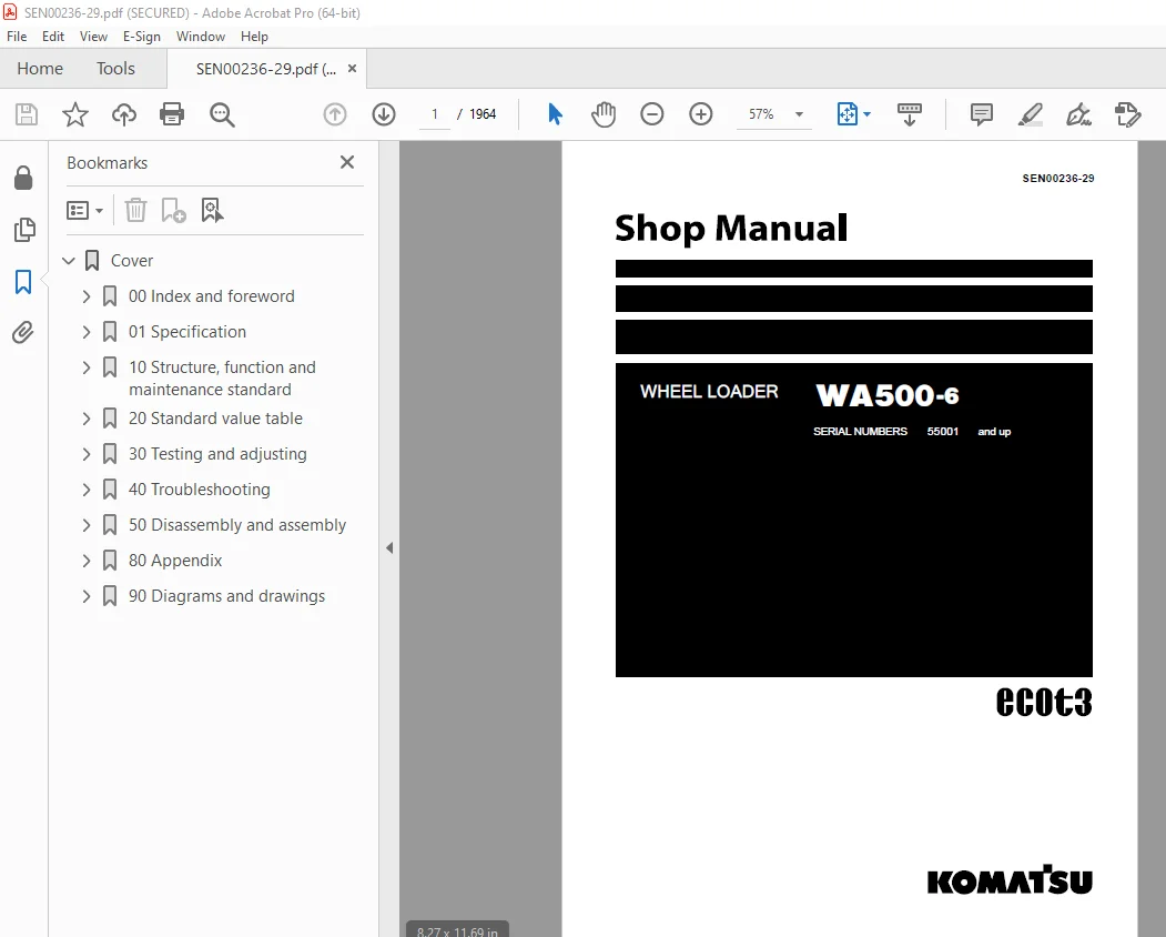
Komatsu WA500-6 Wheel Loader Shop Manual SEN00236-29 PDF
$39.95
Komatsu WA500-6 Wheel Loader Shop Manual SEN00236-29 – PDF DOWNLOAD
SERIAL NUMBERS 55001 and up
Description
Komatsu WA500-6 Wheel Loader Shop Manual SEN00236-29 – PDF DOWNLOAD
FILE DETAILS:
Komatsu WA500-6 Wheel Loader Shop Manual SEN00236-29 – PDF DOWNLOAD
Language : English
Pages : 1964
Downloadable : Yes
File Type : PDF
IMAGES PREVIEW OF THE MANUAL:
TABLE OF CONTENTS:
Komatsu WA500-6 Wheel Loader Shop Manual SEN00236-29 – PDF DOWNLOAD
SERIAL NUMBERS 55001 and up
Cover 1
00 Index and foreword 3
Index 3
Composition of shop manual 4
Table of contents 6
Foreword and general information 21
Safety notice 22
How to read the shop manual 27
Explanation of terms for maintenance standard 29
Handling of electric equipment and hydraulic component 31
Handling of connectors newly used for engines 40
How to read electric wire code 43
Precautions when carrying out operation 46
Method of disassembling and connecting push-pull type coupler 49
Standard tightening torque table 52
Conversion table 56
01 Specification 63
Specification and technical data 63
Specification and technical data 64
Specification dimension drawing 64
Specifications 65
Weight table 68
Table of fuel, coolant and lubricants 70
10 Structure, function and maintenance standard 73
Engine and cooling system 73
Engine and cooling system 74
Cooling system 74
Engine mount and transmission mount 77
Joint 78
Cooling fan pump 80
Cooling fan motor 87
Power train, Part 1 95
Power train, Part 1 96
Power train 96
Power train system diagram 97
Drive shaft 99
Power train piping diagram 102
Torque converter 104
Torque converter regulator valve 122
Transmission 124
Transfer 144
Transmission control valve 146
ECMV 152
Main relief valve and torque converter relief valve 159
Lubrication relief valve 161
Power train, Part 2 163
Power train, Part 2 164
Torque converter oil cooler 164
Torque converter oil filter 165
Center support 168
Axle 170
Differential 172
Limited slip differential 181
Final drive 186
Steering system 191
Steering system 192
Steering piping diagram 192
Steering column 193
Steering control valve 194
Steering valve 205
Stop valve 209
Joystick steering lever linkage (if equipped) 210
Steering cylinder 211
Emergency steering piping diagram (if equipped) 214
Diverter valve 215
Brake system 221
Brake piping diagram 222
Brake valve 224
Slack adjuster 229
Accumulator charge valve 232
PPC relief valve 236
Accumulator (for brake) 238
Brake 240
Parking brake control 243
Parking brake 244
Parking brake solenoid valve 246
Emergency parking brake release valve 248
Undercarriage and frame 251
Undercarriage and frame 252
Axle mount 252
Center hinge pin 257
Hydraulic system, Part 1 261
Hydraulic system, Part 1 262
Hydraulic piping diagram 262
Work equipment control lever linkage 264
Hydraulic tank 265
Steering pump 267
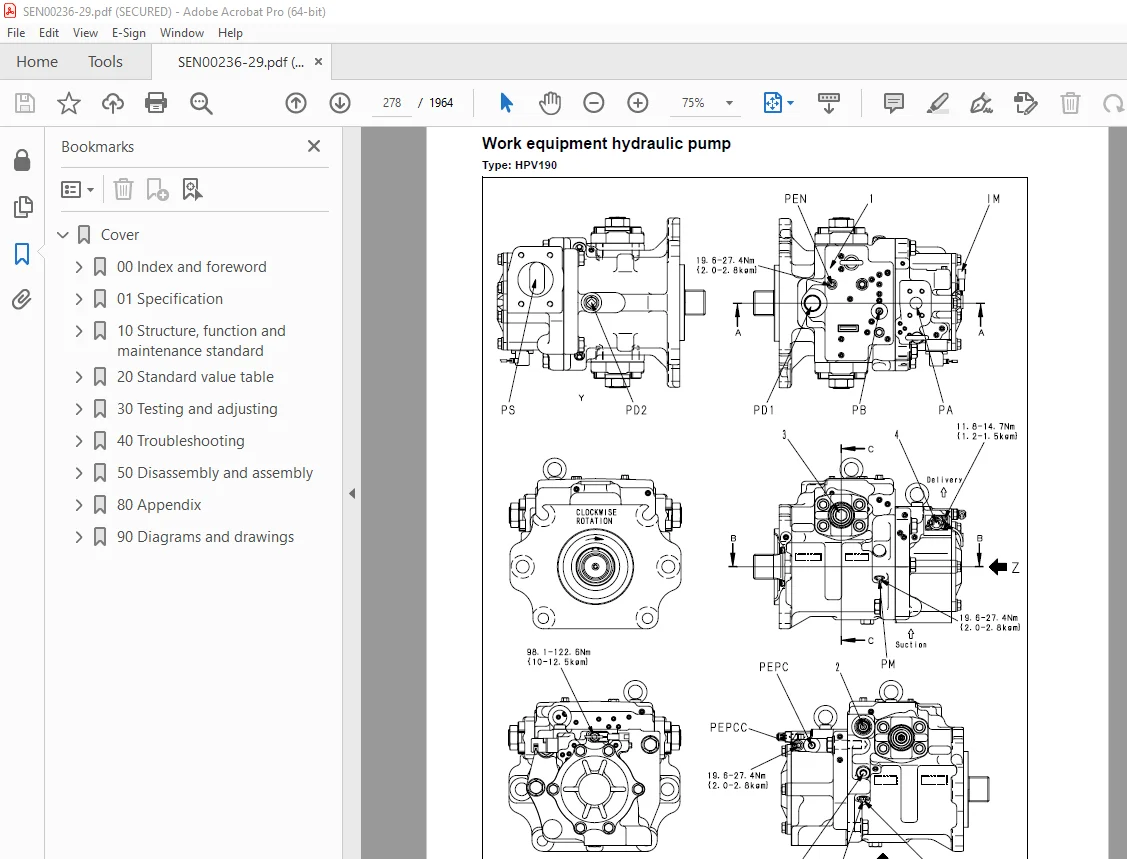
Work equipment hydraulic pump 278
Hydraulic system, Part 2 299
Hydraulic system, Part 2 300
Control valve 300
CLSS 314
Each function and operation of each valve 319
Accumulator (for PPC circuit) 330
Work equipment electric lever 331
Work equipment 335
Work equipment 336
Work equipment linkage 336
Bucket 340
Bucket positioner and boom kick-out 342
Work equipment lubrication 343
Work equipment cylinder 345
Cab and its attachments 347
Cab and its attachments 348
ROPS cab 348
Air conditioner 350
Electrical system, Part 1 359
Electrical system, Part 1 360
Machine monitor system 360
Machine monitor 368
Electrical system, Part 2 423
Electrical system, Part 2 424
Work equipment control system 424
Transmission controller system 458
Electrical system, Part 3 491
Electrical system, Part 3 492
Electric transmission control 492
Engine starting circuit 496
Engine stopping circuit 498
Preheating circuit 499
Parking brake circuit 501
Backup and stop lamp circuits 506
Small lamp and head lamp circuits 508
Working lamp circuit 509
Horn circuit 510
Wiper and window washer circuits 511
Sensor 514
KOMTRAX system 532
20 Standard value table 535
Standard service value table 535
Standard service value table 536
Standard service value table for engine 536
Standard service value table for chassis 537
30 Testing and adjusting 547
Testing and adjusting, Part 1 547
Precautions before work 549
Tools for testing, adjusting, and troubleshooting 550
Measuring engine speed 554
Measuring exhaust gas color 556
Measuring exhaust temperature 558
Adjusting valve clearance 560
Testing compression pressure 561
Measuring blow-by pressure 563
Measuring engine oil pressure 564
Measuring intake air (boost) pressure 565
Handling fuel system equipment 567
Releasing residual pressure in fuel system 567
Testing fuel pressure 568
Testing return rate and leakage 569
Bleeding air from fuel circuit 572
Testing leakage in fuel system 574
Handling reduced cylinder mode operation 575
Handling no injection cranking operation 575
Handling controller voltage circuit 576
Testing and adjusting alternator belt tension 577
Testing and adjusting air conditioner compressor belt tension 578
Adjusting transmission speed sensor 579
Measuring directional lever (Steering wheel specification) 581
Testing and adjusting power train oil pressure 582
Flushing procedure for torque converter and transmission hydraulic circuit 595
Method of moving machine when transmission valve is broken 598
Testing and adjusting, Part 2 601
Testing and adjusting steering stop valve 603
Testing and adjusting steering wheel 605
Testing steering oil pressure 607
Bleeding air from steering cylinder circuit 610
Testing hydraulic drive fan 611
Bleeding air from hydraulic drive fan circuit 614
Measuring brake pedal 616
Measuring brake performance 617
Testing and charging accumulator nitrogen gas pressure for brake 618
Testing ECSS accumulator nitrogen gas pressure and charging accumulator with nitrogen gas 624
Testing and adjusting accumulator charge pressure 631
Testing wheel brake oil pressure 633
Measuring wear of wheel brake disc 635
Bleeding air from brake circuit 636
Releasing residual pressure in brake accumulator circuit 638
Testing parking brake performance 639
Measuring parking brake oil pressure 640
Testing wear of parking brake disc 643
Method of releasing parking brake manually 644
Measuring and adjusting work equipment control lever 645
Testing and adjusting work equipment PPC oil pressure 646
Measuring work equipment oil pressure 648
Bleeding air from work equipment circuit 654
Releasing residual pressure in work equipment circuit 655
Method of moving machine when removing operator cab (when separate cab and floor specification) 656
Testing and adjusting bucket positioner 657
Testing and adjusting lift arm position detecting lever 659
Checking proximity switch operation indication lamp 660
Procedure for testing diodes 661
Preparations for work on troubleshooting of electrical system 662
Testing and adjusting, Part 3 667
Testing and adjusting, Part 3 668
How to start KOMTRAX terminal operations (if equipped) 668
Indicator lamps of KOMTRAX terminal (if equipped) 673
Machine monitor-based adjustment at replacement, disassembly and assembly, and additional installation for each sensor and controller 676
Special functions of machine monitor (EMMS) 678
Testing and adjusting, Part 4 719
Special functions of machine monitor (EMMS) 720
Pm clinic inspection table 758
40 Troubleshooting 763
General information on troubleshooting 763
Precautions before work 764
Points to remember when performing troubleshooting 765
How to proceed in troubleshooting 767
Testing before troubleshooting 769
Classification and procedures of troubleshooting 770
Information in troubleshooting table 774
Troubleshooting method for disconnecting wiring harness of pressure sensor system 776
Connection table for connector pin numbers 778
T- branch box and T- branch adapter table 814
Troubleshooting by failure code (Display of code), Part 1 819
Troubleshooting by failure code (Display of code), Part 1 821
Failure codes list 821
Before carrying out troubleshooting for electrical system 832
Information contained in troubleshooting table 834
Failure code [1500L0] (TORQFLOW transmission : Double meshing) 836
Failure code [15B0NX] (Transmission filter: Clogged) 838
Failure code [15SAL1] (ECMV F clutch: When command current is OFF, fill signal is ON) 840
Failure code [15SALH] (ECMV F clutch: When command current is ON, fill signal is OFF) 842
Failure code [15SBL1] (ECMV R clutch: When command current is OFF, fill signal is ON) 844
Failure code [15SBLH] (ECMV R clutch: When command current is ON, fill signal is OFF) 846
Failure code [15SEL1] (ECMV 1st clutch: When command current is OFF, fill signal is ON) 848
Failure code [15SELH] (ECMV 1st clutch: When command current is ON, fill signal is OFF) 850
Failure code [15SFL1] (ECMV 2nd clutch: When command current is OFF, fill signal is ON) 852
Failure code [15SFLH] (ECMV 2nd clutch: When command current is ON, fill signal is OFF) 854
Failure code [15SGL1] (ECMV 3rd clutch: When command current is OFF, fill signal is ON) 856
Failure code [15SGLH] (ECMV 3rd clutch: When command current is ON, fill signal is OFF) 858
Failure code [15SHL1] (ECMV 4th clutch: When command current is OFF, fill signal is ON) 860
Failure code [15SHLH] (ECMV 4th clutch: When command current is ON, fill signal is OFF) 862
Failure code [2F00MA] (Parking brake: Malfunction) 864
Failure code [2G42ZG] (Front accumulator: Low oil pressure) 866
Troubleshooting by failure code (Display of code), Part 2 869
Failure code [2G43ZG] Rear accumulator: Low oil pressure 872
Failure code [44K0L4] Bucket positioner: ON/OFF signals disagree 874
Failure code [AA1ANX] Air cleaner: Clogging 877
Failure code [AB00L6] Alternator: Signal disagrees with operating state of engine 879
Failure code [AB00MA] Alternator: Malfunction 881
Failure code [B@BAZG] Low engine oil pressure 883
Failure code [B@BAZK] Engine oil: Low level 884
Failure code [B@BCNS] Coolant: Overheating 886
Failure code [B@BCZK] Coolant: Low level 888
Failure code [b@CENS] Torque converter oil: Overheating 890
Failure code [B@CENS] Torque converter oil: Overheating 891
Failure code [B@GAZK] Battery electrolyte: Low level 892
Failure code [B@HANS] Hydraulic oil: Overheating 893
Failure code [CA111] Abnormality in engine controller 894
Failure code [CA115] Engine Ne or Bkup speed sensor error 897
Failure code [CA122] Charge (boost) pressure sensor high error 898
Failure code [CA123] Charge (boost) pressure sensor low error 900
Failure code [CA131] Throttle sensor high error 902
Failure code [CA132] Throttle sensor low error 905
Failure code [CA135] Engine oil pressure sensor high error 908
Failure code [CA141] Engine oil pressure sensor low error 910
Failure code [CA144] Coolant temperature sensor high error 912
Failure code [CA145] Coolant temperature sensor low error 914
Failure code [CA153] Charge (boost) temperature sensor high error 916
Failure code [CA154] Charge (boost) temperature sensor low error 918
Failure code [CA187] Sensor power supply 2 low error 920
Failure code [CA221] Atmospheric pressure sensor high error 924
Failure code [CA222] Atmospheric pressure sensor low error 926
Failure code [CA227] Sensor power supply 2 high error 928
Troubleshooting by failure code (Display of code), Part 3 931
Failure code [CA234] Engine overspeed 933
Failure code [CA238] Ne speed sensor power supply error 934
Failure code [CA263] Fuel Temp Sensor High Error 936
Failure code [CA265] Fuel Temp Sensor Low Error 938
Failure code [CA271] PCV1 Short circuit 940
Failure code [CA272] PCV1 Disconnection 941
Failure code [CA273] PCV2 Short circuit 942
Failure code [CA274] PCV2 Disconnection 943
Failure code [CA322] Injector #1 open/short error 944
Failure code [CA323] Injector #5 open/short error 946
Failure code [CA324] Injector #3 open/short error 948
Failure code [CA325] Injector #6 open/short error 950
Failure code [CA331] Injector #2 open/short error 952
Failure code [CA332] Injector #4 open/short error 954
Failure code [CA342] Calibration code inconsistency 956
Failure code [CA351] Injectors drive circuit error 957
Failure code [CA352] Sens Supply 1 Volt Low Error 958
Failure code [CA386] Sensor power supply 1 high error 960
Failure code [CA431] Idle validation switch error 961
Failure code [CA432] Idle validation action error 964
Failure code [CA441] Battery voltage low error 967
Failure code [CA442] Battery voltage high error 968
Failure code [CA449] Common rail pressure high error 2 969
Failure code [CA451] Rail Press Sensor High Error 970
Failure code [CA452] Rail Press Sensor Low Error 972
Failure code [CA553] Common rail pressure high error 1 974
Failure code [CA554] Common rail pressure sensor in range error 975
Failure code [CA559] Supply pump pressure very low error 1 976
Failure code [CA689] Engine Ne speed sensor error 980
Failure code [CA731] Engine Bkup speed sensor phase error 982
Failure code [CA757] All continuous data lost error 983
Failure code [CA778] Engine Bkup speed sensor error 984
Failure code [CA1228] EGR valve servo error 1 988
Failure code [CA1625] EGR valve servo error 2 989
Failure code [CA1626] Bypass valve solenoid current high error 990
Failure code [CA1627] Bypass valve solenoid current low error 992
Failure code [CA1628] Bypass Valve Servo Error 1 994
Failure code [CA1629] Bypass Valve Servo Error 2 995
Failure code [CA1631] Bypass valve lift sensor high error 996
Failure code [CA1632] Bypass valve lift sensor low error 998
Failure code [CA1633] KOMNET datalink timeout error 1000
Failure code [CA1642] Abnormally low signal in EGR inlet pressure sensor 1002
Failure code [CA1653] Abnormally high signal in EGR inlet pressure sensor 1004
Troubleshooting by failure code (Display of code), Part 4 1007
Failure code [CA2185] Throttle sensor supply voltage high error 1010
Failure code [CA2186] Throttle sensor power supply low error 1012
Failure code [CA2249] Supply pump pressure very low error 2 1014
Failure code [CA2271] EGR valve lift sensor high error 1016
Failure code [CA2272] EGR valve lift sensor low error 1018
Failure code [CA2351] EGR valve solenoid operation short circuit 1020
Failure code [CA2352] EGR valve solenoid operation disconnect 1022
Failure code [CA2555] Intake air heater relay open circuit error 1024
Failure code [CA2556] Intake air heater relay short circuit error 1026
Failure code [D160KZ] Backup lamp relay: Disconnection or short circuit 1028
Failure code [D191KA] Joystick steering neutral safety relay: Disconnection 1030
Failure code [D191KB] Joystick steering neutral safety relay: Short circuit 1032
Failure code [D192KA] ECSS solenoid: Disconnection 1034
Failure code [D192KB] ECSS solenoid: Short circuit 1035
Failure code [D192KY] ECSS solenoid: Short circuit with power supply line 1036
Failure code [D193KA] Joystick steering solenoid cut relay: Disconnection 1038
Failure code [D193KB] Joystick steering solenoid cut relay: Short circuit 1040
Failure code [D193KY] Joystick steering solenoid cut relay: Short circuit with power supply line 1042
Failure code [D5ZHKA] Terminal C signal: Disconnection 1044
Failure code [D5ZHKB] Terminal C signal: Short circuit 1048
Failure code [D5ZHKZ] Terminal C signal: Disconnection or short circuit 1050
Failure code [D5ZHL6] Terminal C signal: Signal does not match engine running or stopped state 1052
Failure code [DA80L4] Auto grease controller: ON/OFF signals disagree 1055
Failure code [DAF3KK] Machine monitor: Low source voltage (input) 1058
Failure code [DAF5KP] Machine monitor: Low output voltage 1060
Failure code [DAFRKR] CAN communication with machine monitor: Communication error (Abnormality in target component system) 1062
Failure code [DAQ0KK] Transmission controller: Low source voltage 1063
Failure code [DAQ0KT] Transmission controller: Abnormality in controller 1066
Failure code [DAQ2KK] Transmission controller load power supply line: Low source voltage (input) 1067
Failure code [DAQ9KQ] Transmission controller model selection: Disagreement of model selection signals 1070
Troubleshooting by failure code (Display of code), Part 5 1073
Failure code [DAQRKR] CAN communication with transmission controller: Communication error (Abnormality in target component system) 1076
Failure code [DAQRMA] Transmission controller option setting: Malfunction 1081
Failure code [DB2RKR] CAN communication from engine controller: Communication error (Abnormality in target component system) 1083
Failure code [DB90KK] Work equipment controller: Low source voltage (input) 1088
Failure code [DB90KT] Work equipment controller: Abnormality in controller 1091
Failure code [DB92KK] Work equipment controller load power supply line: Low source voltage (input) 1092
Failure code [DB95KX] Work equipment controller power supply output: Out of input signal range 1096
Failure code [DB99KQ] Work equipment controller model selection: Disagreement of model selection signals 1098
Failure code [DB9RKR] CAN communication with work equipment controller: Communication error (Abnormality in target component system) 1099
Failure code [DB9RMA] Work equipment controller option setting: Malfunction 1100
Failure code [DB9RMC] CAN communication with work equipment controller: Defective operation 1101
Failure code [DD15LD] t switch (Panel switch 1): Switch is kept pressed for long time 1102
Failure code [DD16LD] U switch (Panel switch 2): Switch is kept pressed for long time 1104
Failure code [DD17LD] < switch (Panel switch 3): Switch is kept pressed for long time 1106
Failure code [DD18LD] > switch (Panel switch 4): Switch is kept pressed for long time 1108
Failure code [DD1ALD] Remote positioner raise/lower set switch (raise): Switch is kept pressed for long time 1110
Failure code [DD1BLD] Remote positioner raise/lower set switch (lower): Switch is kept pressed for long time 1112
Failure code [DD1CLD] Load meter subtotal switch: Switch is kept pressed for long time 1114
Failure code [DD1FLD] Load meter mode selector switch (A/B): Switch is kept pressed for long time 1116
Failure code [DD1GLD] Load meter mode selector switch (+/–): Switch is kept pressed for long time 1118
Failure code [DD1HLD] Load meter display selector switch: Switch is kept pressed for long time 1120
Failure code [DDA7L4] RPM set ON/OFF switch: ON-OFF signals disagree 1122
Failure code [DDA8KB] RPM set idle-up/down selector switch (idle-up): Short circuit 1124
Failure code [DDA9KB] RPM set idle-up/down selector switch (idle-down): Short circuit 1127
Failure code [DDB6L4] Parking brake switch (Neutralizer): ON/OFF signals disagree 1130
Troubleshooting by failure code (Display of code), Part 6 1135
Troubleshooting by failure code (Display of code), Part 6 1138
Failure code [DDD1LD] (Remote positioner bucket angle set switch: Switch is kept pressed for long time) 1138
Failure code [DDE5MA] (Emergency steering drive switch: Malfunction) 1140
Failure code [DDK3KA] (Right FNR switch: Disconnection) 1142
Failure code [DDK3KB] (Right FNR switch: Short circuit) 1144
Failure code [DDK4KA] (Joystick steering FNR switch: Disconnection) 1146
Failure code [DDK4KB] (Joystick steering FNR switch: Short circuit) 1148
Failure code [DDK5L4] (Joystick steering shift-up/down switch: ON/OFF signals disagree) 1150
Failure code [DDK6KA] (FNR lever switch: Disconnection) 1152
Failure code [DDK6KB] (FNR lever switch: Short circuit) 1156
Failure code [DDT0L4] (Shift mode selector switch: ON/OFF signals disagree) 1158
Failure code [DDT4LD] (Transmission cut-off set switch: Switch is kept pressed for long time) 1160
Failure code [DDW9LD] (Kick-down switch: Switch is kept pressed for long time) 1162
Failure code [DDWLLD] (Hold switch: Switch is kept pressed for long time) 1164
Failure code [DDY0LD] (Load meter cancel switch: Switch is kept pressed for long time) 1166
Failure code [DF10KA] (Transmission shift lever switch: Disconnection) 1168
Failure code [DF10KB] (Transmission shift lever switch: Short circuit) 1172
Failure code [DGF1KA] (Transmission oil temperature sensor: Disconnection) 1174
Failure code [DGF1KB] (Transmission oil temperature sensor: Short circuit) 1176
Failure code [DGH2KX] (Hydraulic oil temperature sensor: Out of input signal range) 1178
Failure code [DGR2KA] (Rear brake oil temperature sensor: Disconnection) 1180
Failure code [DGR2KX] (Rear brake oil temperature sensor: Out of input signal range) 1182
Failure code [DGT1KX] (Torque converter oil temperature sensor: Out of input signal range) 1184
Failure code [DH21KA] (Work equipment pump oil pressure sensor: Disconnection) 1186
Troubleshooting by failure code (Display of code), Part 7 1189
Failure code [DH21KB] (Work equipment pump oil pressure sensor: Short circuit) 1192
Failure code [DHPCKX] (Lift arm cylinder bottom pressure sensor: Out of input signal range) 1194
Failure code [DHPDKX] (Lift arm cylinder head pressure sensor: Out of input signal range) 1196
Failure code [DHT1KX] (Left brake pressure sensor: Out of input signal range) 1198
Failure code [DHT2L6] (Transmission filter clogging sensor: Signal disagrees with operating and stopped states of engine) 1200
Failure code [DK59KA] (Lift arm EPC lever potentiometer (Main): Disconnection) 1202
Failure code [DK59KY] (Lift arm EPC lever potentiometer (Main): Short circuit with power supply line) 1205
Failure code [DK59L8] (Lift arm EPC lever potentiometer (Main): Analog signals disagree) 1208
Failure code [DK5AKA] (Lift arm EPC lever potentiometer (Sub): Disconnection) 1212
Failure code [DK5AKY] (Lift arm EPC lever potentiometer (Sub): Short circuit with power supply line) 1215
Failure code [DK5BKA] (Bucket EPC lever potentiometer (Main): Disconnection) 1218
Failure code [DK5BKY] (Bucket EPC lever potentiometer (Main): Short circuit with power supply line) 1221
Failure code [DK5BL8] (Bucket EPC lever potentiometer (Main): Analog signals disagree) 1224
Failure code [DK5CKA] (Bucket EPC lever potentiometer (Sub): Disconnection) 1228
Failure code [DK5CKY] (Bucket EPC lever potentiometer (Sub): Short circuit with power supply line) 1231
Failure code [DK5DKA] (3-spool valve (attachment) EPC lever potentiometer (Main): Disconnection) 1234
Failure code [DK5DKY] (3-spool valve (attachment) EPC lever potentiometer (Main): Short circuit with power supply line) 1237
Failure code [DK5DL8] (3-spool valve (attachment) EPC lever potentiometer (Main): Analog signals disagree) 1239
Failure code [DK5EKA] (3-spool valve (attachment) EPC lever potentiometer (Sub): Disconnection) 1242
Troubleshooting by failure code (Display of code), Part 8 1247
Failure code [DK5EKY] (3-spool valve EPC lever potentiometer (Sub): Short circuit with power supply line) 1250
Failure code [DK5FKA] (Joystick steering EPC lever potentiometer (Main): Disconnection) 1252
Failure code [DK5FKY] (Joystick steering EPC lever potentiometer (Main): Short circuit with power supply line) 1254
Failure code [DK5GKA] (Joystick steering EPC lever potentiometer (Sub): Disconnection) 1256
Failure code [DK5GKY] (Joystick steering EPC lever potentiometer (Sub): Short circuit with power supply line) 1258
Failure code [DK5FL8] (Joystick steering EPC lever potentiometer (Main): Analog signals disagree) 1260
Failure code [DKA0KA] (Lift arm angle sensor: Disconnection) 1264
Failure code [DKA0KX] (Lift arm angle sensor: Out of input signal range) 1266
Failure code [DKA0KY] (Lift arm angle sensor: Short circuit with power supply line) 1268
Failure code [DKA0L0] (Lift arm angle sensor: Double meshing) 1270
Failure code [DLF1KA] (Transmission input shaft speed sensor: Disconnection) 1272
Failure code [DLF1LC] (Transmission input shaft speed sensor: Speed signals disagree) 1274
Failure code [DLT4KB] (Transmission output shaft speed sensor: Short circuit) 1276
Failure code [DLT4KX] (Transmission output shaft speed sensor: Out of input signal range) 1278
Failure code [DT20KB] (Transmission cut-off indicator lamp: Short circuit) 1280
Failure code [DUM1KB] (Remote positioner raise set indicator lamp: Short circuit) 1282
Failure code [DUM2KB] (Remote positioner lower set indicator lamp: Short circuit) 1284
Failure code [DV00KB] (Alarm buzzer: Short circuit) 1286
Failure code [DW4PKA] (Lift arm raise EPC solenoid: Disconnection) 1288
Failure code [DW4PKB] (Lift arm raise EPC solenoid: Short circuit) 1289
Failure code [DW4PKY] (Lift arm raise EPC solenoid: Short circuit with power supply line) 1290
Failure code [DW4QKA] (Lift arm lower EPC solenoid: Disconnection) 1292
Failure code [DW4QKB] (Lift arm lower EPC solenoid: Short circuit) 1293
Failure code [DW4QKY] (Lift arm lower EPC solenoid: Short circuit with power supply line) 1294
Failure code [DW4RKA] (Bucket tilt EPC solenoid: Disconnection) 1296
Failure code [DW4RKB] (Bucket tilt EPC solenoid: Short circuit) 1298
Failure code [DW4RKY] (Bucket tilt EPC solenoid: Short circuit with power supply line) 1300
Troubleshooting by failure code (Display of code), Part 9 1303
Troubleshooting by failure code (Display of code), Part 9 1305
Failure code [DW4SKA] (Bucket dump EPC solenoid: Disconnection) 1305
Failure code [DW4SKB] (Bucket dump EPC solenoid: Short circuit) 1306
Failure code [DW4SKY] (Bucket dump EPC solenoid: Short circuit with power supply line) 1308
Failure code [DW7BKA] (Fan reverse solenoid: Disconnection) 1310
Failure code [DW7BKB] (Fan reverse solenoid: Short circuit) 1312
Failure code [DW7BKY] (Fan reverse solenoid: Short circuit with power supply line) 1314
Failure code [DW7DKA] (Hydraulic drive fan neutral solenoid: Disconnection) 1316
Failure code [DW7DKB] (Hydraulic drive fan neutral solenoid: Short circuit) 1316
Failure code [DW7DKY] (Hydraulic drive fan neutral solenoid: Short circuit with power supply line) 1317
Failure code [DWM1KA] (Work equipment neutral lock solenoid: Disconnection) 1318
Failure code [DWM1KB] (Work equipment neutral lock solenoid: Short circuit) 1320
Failure code [DWM1KY] (Work equipment neutral lock solenoid: Short circuit with power supply line) 1322
Failure code [DWN6KA] (Lift arm raise magnet detent solenoid: Disconnection) 1324
Failure code [DWN6KB] (Lift arm raise magnet detent solenoid: Short circuit) 1326
Failure code [DWN6KY] (Lift arm raise magnet detent solenoid: Short circuit with power supply line) 1328
Failure code [DWN7KA] (Lift arm float magnet detent solenoid: Disconnection) 1330
Failure code [DWN7KB] (Lift arm float magnet detent solenoid: Short circuit) 1332
Failure code [DWN7KY] (Lift arm float magnet detent solenoid: Short circuit with power supply line) 1334
Failure code [DWN8KA] (Bucket tilt magnet detent solenoid: Disconnection) 1336
Failure code [DWN8KB] (Bucket tilt magnet detent solenoid: Short circuit) 1338
Failure code [DWN8KY] (Bucket tilt magnet detent solenoid: Shorted with the power source) 1340
Failure code [DX16KA] (Fan pump EPC solenoid: Disconnection) 1342
Failure code [DX16KB] (Fan pump EPC solenoid: Short circuit) 1343
Failure code [DX16KY] (Fan pump EPC solenoid: Short circuit with power supply line) 1344
Failure code [DXA1KA] (Pump PC-EPC solenoid: Disconnection) 1345
Failure code [DXA1KB] (Pump PC-EPC solenoid: Short circuit) 1346
Failure code [DXH1KA] (Lockup ECMV solenoid: Disconnection) 1347
Failure code [DXH1KB] (Lockup ECMV solenoid: Short circuit) 1348
Failure code [DXH1KY] (Lockup ECMV solenoid: Short circuit with power supply line) 1350
Failure code [DXH4KA] (1st clutch ECMV solenoid: Disconnection) 1352
Failure code [DXH4KB] (1st clutch ECMV solenoid: Short circuit) 1354
Troubleshooting by failure code (Display of code), Part 10 1357
Troubleshooting by failure code (Display of code), Part 10 1360
Failure code [DXH4KY] (1st clutch ECMV solenoid: Short circuit with power supply line) 1360
Failure code [DXH5KA] (2nd clutch ECMV solenoid: Disconnection) 1362
Failure code [DXH5KB] (2nd clutch ECMV solenoid: Short circuit) 1364
Failure code [DXH5KY] (2nd clutch ECMV solenoid: Short circuit with power supply line) 1366
Failure code [DXH6KA] (3rd clutch ECMV solenoid: Disconnection) 1368
Failure code [DXH6KB] (3rd clutch ECMV solenoid: Short circuit) 1370
Failure code [DXH6KY] (3rd clutch ECMV solenoid: Short circuit with power supply line) 1372
Failure code [DXH7KA] (R clutch ECMV solenoid: Disconnection) 1374
Failure code [DXH7KB] (R clutch ECMV solenoid: Short circuit) 1376
Failure code [DXH7KY] (R clutch ECMV solenoid: Short circuit with power supply line) 1378
Failure code [DXH8KA] (F clutch ECMV solenoid: Disconnection) 1380
Failure code [DXH8KB] (F clutch ECMV solenoid: Short circuit) 1382
Failure code [DXH8KY] (F clutch ECMV solenoid: Short circuit with power supply line) 1384
Failure code [DXHHKA] (4th clutch ECMV solenoid: Disconnection) 1386
Failure code [DXHHKB] (4th clutch ECMV solenoid: Short circuit) 1388
Failure code [DXHHKY] (4th clutch ECMV solenoid: Short circuit with power supply line) 1390
Failure code [DXHJKA] (3-spool valve extract EPC solenoid: Disconnection) 1392
Failure code [DXHJKB] (3-spool valve extract EPC solenoid: Short circuit) 1393
Failure code [DXHJKY] (3-spool valve extract EPC solenoid: Short circuit with power supply line) 1394
Failure code [DXHKKA] (3-spool valve retract EPC solenoid: Disconnection) 1395
Failure code [DXHKKB] (3-spool valve retract EPC solenoid: Short circuit) 1396
Failure code [DXHKKY] (3-spool valve retract EPC solenoid: Short circuit with power supply line) 1397
Failure code [DXHLKA] (Joystick steering right EPC solenoid: Disconnection) 1398
Failure code [DXHLKB] (Joystick steering right EPC solenoid: Short circuit) 1400
Failure code [DXHLKY] (Joystick steering right EPC solenoid: Short circuit with power supply line) 1402
Failure code [DXHMKA] (Joystick steering left EPC solenoid: Disconnection) 1404
Failure code [DXHMKB] (Joystick steering left EPC solenoid: Short circuit) 1406
Failure code [DXHMKY] (Joystick steering left EPC solenoid: Short circuit with power supply line) 1408
Troubleshooting of electrical system (E-mode) 1411
Before carrying out troubleshooting of electrical system 1413
Information in troubleshooting table 1416
E-1 Engine does not start 1417
E-2 Wiper does not operate 1422
E-3 Windshield washer does not operate 1426
E-4 Headlamp, clearance lamp, tail lamp, and license lamp do not light up or go off 1429
E-5 Working lamp does not light up or go off 1437
E-6 Turn signal lamp and hazard lamp do not light up or go off 1442
E-7 Brake lamp does not light or it keeps lighting up 1448
E-8 Backup lamp does not light or it keeps lighting up 1450
E-9 Backup buzzer does not sound or it keeps sounding 1452
E-10 Horn does not sound or it keeps sounding 1454
E-11 Alarm buzzer does not sound or it keeps sounding 1457
E-12 Air conditioner does not operate or stop 1459
E-13 KOMTRAX system does not work properly 1462
Troubleshooting of hydraulic and mechanical system (H-mode) 1465
Troubleshooting of hydraulic and mechanical system (H-mode) 1467
Method of using troubleshooting chart 1467
Table of failure modes and causes 1470
H-1 Machine does not start 1474
H-2 Torque converter lockup is not switched off (engine stalls) [Machine with lockup clutch (if equipped)] 1476
H-3 Torque converter lockup is not switched ON [Machine with lockup clutch (if equipped)] 1477
H-4 Travel speed is slow, thrusting force is weak, uphill traveling power is weak, and gear is not shifted 1478
H-5 Shocks are large at the times of starting and shifting gear 1480
H-6 Time lag is large at the times of starting and shifting gear 1482
H-7 Torque converter oil temperature is high 1484
H-8 Steering does not turn 1485
H-9 Steering does not turn [Machine with joystick steering (if equipped)] 1486
H-10 Steering response is low 1487
H-11 Turning response of steering is poor [machine with joystick steering (if equipped)] 1488
H-12 Steering is heavy 1489
H-13 When machine turns, it shakes or makes large shocks 1490
H-14 When machine turns, it shakes or makes large shocks [machine with joystick steering (if equipped)] 1491
H-15 Wheel brake does not work or does not work well 1492
H-16 Wheel brake is not released or it drags 1493
H-17 Parking brake does not work or does not work well 1494
H-18 Parking brake is not released or it drags (including emergency release system) 1495
H-19 Lift arm does not rise 1496
H-20 Lift arm speed is low or rising force of lift arm is insufficient 1497
H-21 When rising, lift arm comes to move slowly at specific height 1498
H-22 Lift arm cylinder cannot hold down bucket (Bucket floats) 1498
H-23 Hydraulic drifts of lift arm occur often 1498
H-24 Lift arm wobbles during operation 1498
H-25 Bucket does not tilt back 1499
H-26 Bucket speed is low or tilting back force is insufficient 1500
H-27 Bucket comes to operate slowly in the midst of tilting-back 1501
H-28 Bucket cylinder cannot hold down the bucket 1501
H-29 Hydraulic drifts of bucket occur often 1501
H-30 Bucket wobbles during travel with cargo (Work equipment valve is set to “HOLD”) 1501
H-31 During operation of machine, engine speed lowers remarkably or engine stalls 1502
H-32 Large shocks are made when work equipment starts and stops 1502
H-33 When work equipment circuit is relieved singly, other work equipment moves 1502
H-34 ECSS does not operate, and pitching and bouncing occur 1503
Troubleshooting of engine (S-mode) 1505
Troubleshooting of engine (S-mode) 1507
Method of using troubleshooting chart 1507
S-1 Engine does not start easily 1510
S-2 Engine does not start 1512
S-3 Engine does not pick up smoothly 1516
S-4 Engine stops during operation 1517
S-5 Engine does not rotate smoothly (Engine hunts ) 1518
S-6 Engine lacks output (or lacks power) 1519
S-7 Exhaust smoke is black (Incomplete combustion) 1520
S-8 Oil is consumed much (or exhaust gas color is blue) 1522
S-9 Engine oil becomes contaminated quickly 1523
S-10 Fuel consumption is excessive 1524
S-11 Coolant contains oil (blows back or reduces) 1525
S-12 Oil pressure drops 1526
S-13 Oil level rises (Water, fuel in oil) 1527
S-14 Coolant temperature rises too high (Overheating) 1529
S-15 Abnormal noise is made 1530
S-16 Vibration is excessive 1531
50 Disassembly and assembly 1533
General information on disassembly and assembly 1533
Precautions before work 1534
How to read this manual 1535
Coating materials list 1537
Special tool list 1540
Sketches of special tools 1544
Engine and cooling system, Part 1 1553
Removal and installation of engine assembly 1554
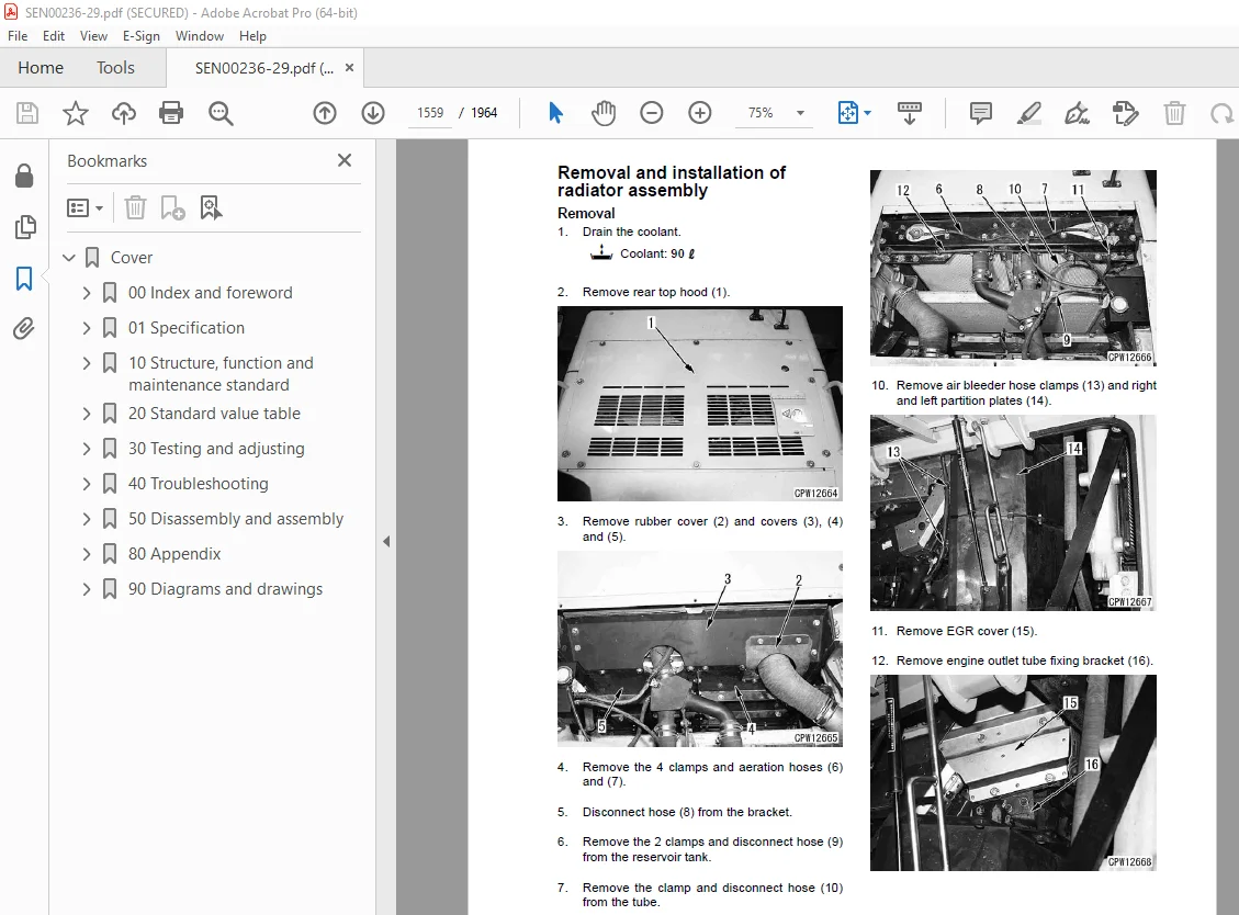
Removal and installation of radiator assembly 1559
Removal and installation of air aftercooler 1561
Removal and installation of cooling fan and fan motor assembly 1562
Removal and installation of radiator guard and cooling fan motor assembly 1564
Removal and installation of fuel tank assembly 1567
Removal and installation of hood 1569
Engine and cooling system, Part 2 1573
Removal and installation of fuel supply pump assembly 1574
Removal and installation of cylinder head assembly 1578
Removal and installation of fuel injector assembly 1589
Removal and installation of engine front seal 1592
Removal and installation of engine rear seal 1596
Power train, Part 1 1603
Removal and installation of torque converter and transmission assembly 1604
Disconnection and connection of power train unit 1610
1 Set torque converter and transmission assembly (1) 1611
2 Torque converter assembly 1611
3 Input transfer 1612
4 Transmission assembly 1612
Disassembly and assembly of input transfer assembly 1614
1 Disconnect the input transfer assembly from the power train unit For details, see “Disconnection and connection of power train unit” 1614
2 Input shaft 1614
3 Bearing cage assembly (Drive gear side) 1614
4 Drive gear assembly 1615
5 Outer race (Drive gear side) 1615
6 Bearing cage assembly (Driven gear side) 1615
8 Outer race 1616
1 Outer race (Driven gear side) 1616
2 Driven gear assembly 1616
3 Bearing cage assembly (Driven gear side) 1617
4 Outer race (Drive gear side) 1618
5 Drive gear assembly 1618
6 Bearing cage assembly (Drive gear side) 1618
7 Input shaft 1620
8 Connect the input transfer assembly to the power train unit For details, see “Disconnection and connection of power train unit” 1620
Disassembly and assembly of torque converter assembly (Lockup specification) 1621
1 Disconnect the torque converter assembly from the power train unit For details, see “Disconnection and connection of power train unit” 1621
2 Torque converter assembly 1621
3 Housing 1621
5 Torque converter assembly 1621
6 Turbine assembly 1622
7 Snap ring and spacer 1622
8 Turbine boss assembly 1622
9 Drive case assembly 1622
10 Stator assembly 1623
11 Pump assembly 1623
12 PTO gear A assembly 1624
13 PTO gear B assembly 1625
14 Idler gear 1626
2 PTO gear B assembly 1627
3 PTO gear A assembly 1627
4 Pump assembly 1628
5 Stator assembly 1630
6 Turbine assembly 1630
7 Drive case assembly 1630
8 Piston housing assembly 1631
9 Snap ring and spacer 1632
10 Turbine assembly 1632
11 Pilot 1632
12 Torque converter assembly 1632
13 Housing 1633
14 Connect the torque converter assembly to the power train unit For details, see “Disconnection and connection of power train unit” 1633
Disassembly and assembly of torque converter assembly (Lockup-less specification) 1634
1 Disconnect the torque converter assembly from the power train unit For details, see “Disconnection and connection of power train unit” 1634
2 Housing 1634
3 Pilot 1634
4 Torque converter assembly 1634
5 Turbine assembly 1634
6 Snap ring and spacer 1635
7 Turbine boss assembly 1635
8 Drive case assembly 1635
9 Stator 1635
10 Pump assembly 1635
11 PTO gear A assembly 1636
12 PTO gear B assembly 1637
13 Idler gear 1638
1 Idler gear 1638
2 PTO gear B assembly 1639
3 PTO gear A assembly 1639
4 Pump assembly 1640
5 Stator 1642
6 Turbine assembly 1642
7 Drive case assembly 1642
8 Snap ring and spacer 1642
9 Turbine assembly 1643
10 Pilot 1643
11 Torque converter assembly 1643
12 Housing 1644
13 Connect the torque converter assembly to the power train unit For details, see “Disconnection and connection of power train unit” 1644
Power train, Part 2 1647
Disassembly and assembly of transmission assembly 1648
1 Disconnect the transmission assembly from the power train unit For details, see “Uncoupling and coupling of power train unit” 1648
2 Sleeves 1648
3 Transmission assembly 1648
4 Check of clutch piston operation 1649
5 Input shaft and No 1 carrier housing assembly 1649
6 No 1 spring 1651
7 No 1 plate, spring and No 1 disc 1651
8 Guide pin and piston 1651
9 No 1 and No 2 piston housing assembly 1652
10 No 2 piston 1652
11 No 2 spring 1653
12 No 2 disc, spring and No 2 plate 1653
13 No 2 carrier and housing assembly 1653
14 Guide pin and plate 1654
15 No 3 spring 1654
16 No 3 disc, spring and No 3 plate 1654
17 Plate 1655
18 No 3 ring gear 1655
19 No 3 and No 4 housing and piston assembly 1655
20 No 3 piston assembly 1655
21 Plate 1655
22 No 4 spring 1655
23 No 4 disc, spring and No 4 plate 1655
24 Plate 1656
25 No 3 and No 4 carrier assembly 1656
26 No 4 sun gear 1657
27 No 4 ring gear 1658
28 No 5 housing and No 5 piston assembly 1658
29 No 5 plate 1658
30 No 5 spring 1658
31 Remove 3 No 5 discs (121), 15 springs (122) and 2 No 5 plates (123) 1658
32 Remove 5 guide pins (124) 1658
33 Remove No 5 ring gear (125) 1659
34 Remove No 5 plate (126) 1659
35 Remove bearing (127) 1659
36 No 5 sun gear 1659
37 No 5 carrier assembly 1659
38 No 6 plate 1660
39 No 6 spring 1660
40 Remove 4 No 6 discs (139), 20 springs (140) and 3 No 6 plates (141) 1660
41 Remove 5 guide pins (142) 1660
42 No 6 piston 1660
43 No 6 hub 1660
44 Output shaft 1660
45 Cage assembly 1661
46 No 6 housing assembly 1661
1 No 6 housing assembly 1662
2 Cage assembly 1662
3 Output shaft 1662
4 Seal ring 1663
5 Guide pin 1663
6 No 6 pin 1663
7 No 6 hub 1663
8 No 6 plate, spring and No 6 disc 1663
9 No 6 spring 1663
10 No 6 plate 1663
11 No 5 carrier assembly 1664
12 No 5 sun gear 1664
13 Install the bearing and spacer assembly (127) 1665
14 Install No 5 plate (126) 1665
15 Install No 5 ring gear (125) 1665
16 Install 5 guide pins (124) 1665
17 Install 2 No 5 plates (123), 3 No 5 discs (121) and 15 springs (122) alternately 1665
18 Install 10 No 5 springs (120) 1665
19 No 5 plate 1665
20 Install No 5 housing and No 5 piston assembly 1665
21 No 4 ring gear 1666
22 No 4 sun gear and spacer 1666
23 Plate 1666
24 No 4 plate, spring and No 4 disc 1666
25 No 4 spring 1666
26 Plate 1667
27 No 3 piston and No 4 piston assembly 1667
28 No 3 and No 4 housing assembly 1667
29 No 3 and No 4 carrier assembly 1667
30 Guide pin 1669
31 No 3 ring gear 1669
32 Plate 1669
33 No 3 plate, spring and No 3 disc 1669
34 No 3 spring 1669
35 Plate 1669
36 No 2 carrier and housing assembly 1670
37 No 2 disc, spring and No 2 plate 1671
38 No 1 and No 2 piston housing assembly 1672
39 Using eyebolts [15], install No 1 and No 2 piston housing assembly (42) 1672
40 No 1 carrier assembly 1673
41 Input shaft 1674
42 Spacer and sun gear 1674
43 Bearing and spacer 1674
44 No 2 sun gear 1674
45 Input shaft and No 1 carrier assembly 1674
46 Guide pin 1674
47 No 1 plate, spring and No 1 disc 1675
48 No 1 spring 1675
49 No 1 housing 1675
50 Check of operation and stroke of clutch piston 1676
51 Transmission assembly 1676
52 Sleeve 1677
53 Couple the transmission assembly with the power train unit For details, see “Uncoupling and coupling of power train unit” 1677
Disassembly and assembly of transfer and parking brake assembly 1678
1 Disconnect the transfer and parking brake assembly from the power train unit For details, see “Disconnection and connection of power train unit” 1678
2 Remove strainer (1) and drain valve (2) 1678
3 Remove speed sensor (3) 1678
4 Input shaft bearing cage assembly 1678
5 Input shaft gear assembly 1679
6 Outer race (Input shaft side) 1679
7 Cover (Input shaft side) 1679
8 Intermediate shaft bearing cage assembly 1679
9 Intermediate shaft gear assembly 1680
10 Outer race (Intermediate shaft side) 1680
11 Parking brake emergency release valve 1680
12 Coupling (Rear side) 1681
13 Parking brake assembly 1681
14 Cover assembly 1681
15 Spring 1682
16 Spacer assembly 1682
17 Piston 1682
18 Gear 1682
19 Plate 1682
20 Snap ring and end plate 1683
21 Plate, disc and wave spring 1683
22 End plate 1683
23 Coupling (Front side) 1683
24 Seal cage 1683
25 Output shaft 1684
26 Output shaft bearing cage assembly 1684
27 Output shaft gear 1684
1 Outer race (Intermediate shaft side) 1685
2 Intermediate shaft gear assembly 1685
3 Bearing cage assembly (Intermediate shaft gear side) 1685
4 Cover (Input shaft side) 1686
5 Outer race (Input shaft side) 1686
6 Input shaft gear assembly 1686
7 Bearing cage assembly (Input shaft gear side) 1687
8 Output shaft gear assembly 1688
9 Outer race and output shaft 1688
10 Output shaft bearing cage assembly 1688
11 Output shaft bearing 1688
12 Outer race 1688
13 Seal cage 1689
14 Coupling (Front side) 1690
15 Intermediate shaft gear assembly 1690
16 Cover 1690
17 Spacer assembly 1690
18 Spring 1690
19 Piston 1691
20 Plug 1691
21 Housing 1691
22 Gear 1691
23 Plate, disc and wave spring 1692
24 Snap ring and end plate 1692
25 Plate 1692
26 Seal cage 1692
27 Parking brake assembly 1693
28 Sleeve 1694
29 Coupling (Rear side) 1694
30 Speed sensor 1694
31 Install strainer (1) and drain valve (2) 1694
32 Connect the transfer and parking brake assembly to the power train unit For details, see “Disconnection and connection of power train unit” 1694
Removal and installation of front axle assembly 1695
Removal and installation of rear axle assembly 1697
Power train, Part 3 1701
Removal and installation of front differential assembly 1702
Disassembly and assembly of differential assembly (LSD specification) 1704
1 Set differential assembly (1) to tool H1 1704
2 Differential gear and case assembly 1704
3 Gear case cover A 1705
4 Disc and plate 1705
5 Pressure ring A 1705
6 Side gear A 1705
7 Cross shaft and pinion gear 1705
8 Side gear B 1706
9 Pressure ring B 1706
10 Disc and plate 1706
11 Gear case cover B 1706
12 Coupling 1706
13 Pinion assembly 1707
1 Bevel gear assembly 1708
2 Gear case cover B 1708
3 Disc and plate 1708
4 Pressure ring B 1708
5 Side gear B 1709
6 Cross shaft and pinion gear 1709
7 Side gear A 1709
8 Pressure ring A 1709
9 Disc and plate 1709
10 Gear case cover A 1711
11 Differential gear and carrier assembly 1712
12 Pinion assembly 1714
13 Adjusting tooth contact and backlash 1715
14 Lock 1717
15 Differential assembly 1717
Disassembly and assembly of differential assembly (LSD-less specification) 1718
1 Set differential assembly (1) to tool H1 1718
2 Differential gear and case assembly 1718
3 Gear case cover A 1719
4 Side gear A 1719
5 Cross shaft and pinion gear 1719
6 Side gear B 1719
7 Gear case cover B 1720
8 Coupling 1720
9 Pinion assembly 1720
1 Bevel gear assembly 1721
2 Gear case cover B 1722
3 Side gear B 1722
4 Cross shaft and pinion gear 1722
5 Side gear A 1722
6 Gear case cover A 1722
7 Differential gear and carrier assembly 1723
8 Pinion assembly 1725
9 Adjusting tooth contact and backlash 1726
10 Lock 1728
11 Differential assembly 1728
Disassembly and assembly of final drive assembly (Front and rear) 1729
1 Tire wheel assembly 1729
2 Draining oil 1729
3 Cover 1729
4 Drive shaft 1729
5 Planetary carrier assembly 1730
6 Ring gear 1730
1 Ring gear 1731
2 Planetary carrier 1734
3 Drive shaft 1734
4 Cover 1735
5 Refilling with oil 1735
6 Tire wheel assembly 1735
Brake system 1737
Removal and installation of brake assembly (Front and rear) 1738
Disassembly and assembly of brake assembly (Front and rear) 1742
Disassembly and assembly of slack adjuster assembly 1748
Disassembly and assembly of brake accumulator charge valve assembly 1749
Undercarriage and frame 1751
Removal and installation of center hinge pin 1752
Hydraulic system 1761
Removal and installation of hydraulic tank assembly 1762
Removal and installation of cooling pump assembly 1765
Removal and installation of fan pump assembly 1766
Removal and installation of work equipment pump assembly 1767
Removal and installation of steering, torque converter charge and EPC pump assembly 1769
Removal and installation of work equipment valve assembly 1770
Disassembly and assembly of work equipment control valve assembly 1773
Disassembly and assembly of steering cylinder assembly 1776
1 Set cylinder assembly (1) to tool U1 1776
2 Using tool U7, remove cylinder head (2) from the cylinder 1776
3 Pull cylinder head and piston rod assembly (3) out of cylinder (4) and lift it off 1776
4 Remove cylinder (4) from tool U1 1776
5 Set the cylinder head and piston rod assembly to tool U1 and loosen nut (5) with torque multiplier [1] and socket U3 1776
6 Remove nut (5) and then remove piston assembly (6) and cylinder head assembly (7) from rod (8) 1777
7 Disassembly of piston assembly 1777
8 Disassembly of cylinder head assembly 1777
1 Assembly of cylinder head assembly 1778
2 Assembly of piston assembly 1778
3 Set piston rod (8) to tool U1 1779
4 Install cylinder head assembly (7) and piston assembly (6) to the rod and install nut (5) 1779
5 Using torque multiplier [1] and socket U3, tighten nut (5) 1779
6 Remove piston rod and head assembly (3) from tool U1 1779
7 Set cylinder (4) to tool U1 1779
8 Sling piston rod and head assembly (3) and install it to cylinder (4) 1779
9 Using tool U7, tighten cylinder head nut (2) 1779
10 Remove the cylinder assembly from tool U1 1779
Disassembly and assembly of lift arm and/bucket cylinder assembly 1780
1 Set cylinder assembly (1) to tool U1 1780
2 Remove mounting bolt (2) of the cylinder head 1780
3 Set the cylinder to tool U1 and pull cylinder head and piston rod assembly (3) out of cylinder (4) and lift it off 1780
4 Disassemble the piston rod assembly according to the following procedure 1780
5 Remove piston assembly lock screw (5) 1780
6 Using tool U2, remove piston assembly (6) 1781
7 Remove cylinder head assembly (7) from piston rod assembly (9) 1781
8 Disassembly of piston assembly 1781
9 Disassembly of cylinder assembly 1781
1 Assemble the cylinder head assembly according to the following procedure 1782
2 Assemble the piston assembly according to the following procedure 1783
3 Install cylinder head assembly (7) to piston rod (9) 1784
4 Piston rod assembly 1784
5 Set cylinder (4) to tool U1 and sling cylinder head and piston rod assembly (3) and install it to the cylinder 1785
Removal and installation of steering valve assembly 1786
Work equipment 1789
Removal and installation of work equipment assembly 1790
Removal and installation of large counterweight assembly 1794
Removal and installation of small counterweight assembly 1795
Electrical system 1851
Removal and installation of engine controller assembly 1852
Removal and installation of transmission controller assembly 1853
Removal and installation of work equipment controller assembly 1854
Removal and installation of KOMTRAX terminal assembly 1855
Removal and installation of air conditioner unit assembly 1856
Cab and its attachments 1797
Removal and installation of operator’s cab assembly (Separate cab and floor specification) 1798
Removal and installation of operator’s cab and floor frame assembly (Cab-floor unit specification) 1803
Removal and installation of operator’s cab glass (Stuck glass) 1807
Disassembly and assembly of operator’s seat assembly 1816
1 Removal and installation of storage box 1816
2 Removal and installation of seat pad and backrest upholstery 1816
3 Removal and installation of mechanical lumbar support 1817
4 Removal and installation of armrests 1817
5 Disassembly and assembly of backrest 1818
6 Disassembly and assembly of backrest adjustment 1819
7 Disassembly and assembly of seat angle and seat depth adjuster 1819
8 Removal and installation of covers 1821
9 Removal and installation of slide rails 1822
1 Removal and installation of top cover 1823
2 Removal and installation of front cover 1823
3 Removal and installation of bellows 1824
4 Removal and installation of Bowden pull wire and handle for vertical shock absorber adjustment 1825
5 Removal and installation of vertical shock absorber 1827
6 Removal and installation of compressor 1828
7 Removal and installation of height level controller 1830
8 Removal and installation of compressed-air hoses 1833
9 Removal and installation of Bowden pull wires and handle for height adjustment 1835
10 Removal and installation of pneumatic spring 1838
11 Removal and installation of air tank for additional air supply 1840
12 Removal and installation of cable harness 1841
13 Disassembly and assembly of upper part of the suspension system 1843
14 Lower part of the suspension system 1845
15 Swinging structure 1847
80 Appendix 1861
Air conditioner 1861
Precautions before work 1863
Precautions for refrigerant 1864
Troubleshooting procedure 1865
Circuit diagram and arrangement of connector pins 1867
System diagram 1872
Detail of air conditioner unit 1874
Parts and connectors layout 1876
Testing with self-diagnosis function (indication on control panel) 1880
Testing temperature control 1883
Testing vent (mode) changeover 1884
Testing Fresh/Recirc changeover 1886
Testing inside air temp sensor and outside air temp sensor 1888
Testing evaporator temperature sensor 1890
Testing sunlight sensor 1891
Testing relays 1892
Troubleshooting chart 1 1893
Troubleshooting chart 2 1894
Information in troubleshooting table 1897
Troubleshooting for power supply system (Air conditioner does not operate) 1898
Troubleshooting for compressor and refrigerant system (Air is not cooled) 1901
Troubleshooting for blower motor system (No air comes out or air flow is abnormal) 1904
Troubleshooting for temperature control 1910
Troubleshooting for vent (mode) changeover 1913
Troubleshooting for Fresh/Recirc air changeover 1916
Troubleshooting with gauge pressure 1918
Connection of service tool 1920
Precautions for disconnecting and connecting hoses and tubes in air conditioner circuit 1921
Handling of compressor oil 1923
90 Diagrams and drawings 1927
Hydraulic diagrams and drawings 1927
Automatic greasing circuit diagram 1928
Power train hydraulic circuit diagram 1931
Brake hydraulic circuit diagram 1935
Work equipment hydraulic circuit diagram 1939
Electrical diagrams and drawings 1943
Engine electrical circuit diagram 1944
Air conditioner electrical circuit diagram 1945
Electrical circuit diagram 1947
Connector arrangement diagram 1961
DESCRIPTION:
Komatsu WA500-6 Wheel Loader Shop Manual SEN00236-29 – PDF DOWNLOAD
SERIAL NUMBERS 55001 and up
How to read the shop manual 1
1. Composition of shop manual
This shop manual contains the necessary technical information for services performed in a workshop.
For ease of understanding, the manual is divided into the following sections.
00. Index and foreword
This section explains the shop manuals list, table of contents, safety, and basic information.
01. Specification
This section explains the specifications of the machine.
10. Structure, function and maintenance standard
This section explains the structure, function, and maintenance standard values of each component.
The structure and function sub-section explains the structure and function of each component. It
serves not only to give an understanding of the structure, but also serves as reference material for
troubleshooting. The maintenance standard sub-section explains the criteria and remedies for disassembly
and service.
20. Standard value table
This section explains the standard values for new machine and judgement criteria for testing,
adjusting, and troubleshooting. This standard value table is used to check the standard values in
testing and adjusting and to judge parts in troubleshooting.
30. Testing and adjusting
This section explains measuring instruments and measuring methods for testing and adjusting, and
method of adjusting each part. The standard values and judgement criteria for testing and adjusting
are explained in Testing and adjusting.
40. Troubleshooting
This section explains how to find out failed parts and how to repair them. The troubleshooting is
divided by failure modes. The “S mode” of the troubleshooting related to the engine may be also
explained in the Chassis volume and Engine volume. In this case, see the Chassis volume.
50. Disassembly and assembly
This section explains the special tools and procedures for removing, installing, disassembling, and
assembling each component, as well as precautions for them. In addition, tightening torque and
quantity and weight of coating material, oil, grease, and coolant necessary for the work are also
explained.
90. Diagrams and drawings (chassis volume)/Repair and replacement of parts (engine volume)
q Chassis volume
This section gives hydraulic circuit diagrams and electrical circuit diagrams.
q Engine volume
This section explains the method of reproducing, repairing, and replacing parts.
S.V 29/12/24



