Komatsu WA600-6 Galeo Wheel Loader Shop Manual – PDF DOWNLOAD
Original price was: $49.95.$28.95Current price is: $28.95.
Komatsu WA600-6 Galeo Wheel Loader Shop Manual
Description
Komatsu WA600-6 Galeo Wheel Loader Shop Manual
DESCRIPTION:
Komatsu WA600-6 Galeo Wheel Loader Shop Manual
SAFETY PRECAUTIONS:
1. General precautions k Mistakes in operation are extremely dangerous. Read the Operation and Maintenance Manual carefully before operating the machine.
1) Before carrying out any greasing or repairs, read all the safety plates stuck to the machine. For the locations of the safety plates and detailed explanation of precautions, see the Operation and Maintenance Manual.
2) Decide a place in the repair workshop to keep tools and removed parts. Always keep the tools and parts in their correct places. Always keep the work area clean and make sure that there is no dirt, water, or oil on the floor. Smoke only in the areas provided for smoking. Never smoke while working.
3) When carrying out any operation, always wear safety shoes and helmet. Do not wear loose work clothes, or clothes with buttons missing. q Always wear safety glasses when hitting parts with a hammer. q Always wear safety glasses when grinding parts with a grinder, etc.
4) When carrying out any operation with 2 or more workers, always agree on the operating procedure before starting. Always inform your fellow workers before starting any step of the operation. Before starting work, hang UNDER REPAIR warning signs in the operator’s compartment.
5) Only qualified workers must carry out work and operation which require license or qualification.
6) Keep all tools in good condition, learn the correct way to use them, and use the proper ones of them. Before starting work, thoroughly check the tools, machine, forklift, service car, etc.
7) If welding repairs are needed, always have a trained and experienced welder carry out the work. When carrying out welding work, always wear welding gloves, apron, shielding goggles, cap and other clothes suited for welding work.
8) Before starting work, warm up your body thoroughly to start work under good condition.
TABLE OF CONTENTS:
Komatsu WA600-6 Galeo Wheel Loader Shop Manual
00 Index and foreword
Index SEN00398-05
Composition of shop manual 2
Table of contents 4
Foreword and general information SEN00415-01
Safety notice 2
How to read the shop manual 7
Explanation of terms for maintenance standard 9
Handling electric equipment and hydraulic component 11
How to read electric wire code 23
Precautions when carrying out operation 26
Method of disassembling and connecting push-pull type coupler 29
Standard tightening torque table 32
Conversion table 36
01 Specification
Specification and technical data SEN00400-02
Specification and technical data 2
Specification dimension drawing 2
Specifications 3
Weight table 10
Table of fuel, coolant and lubricants 12
10 Structure, function and maintenance standard
Engine and cooling system SEN00402-01
Engine and cooling system 2
Engine mount and transmission mount 2
Cooling system 6
Cooling fan pump 10
Cooling fan motor 18
Power train, Part 1 SEN00403-02
Power train, Part 1 2
Power train 2
Power train system diagram 3
Torque converter and transmission piping diagram 4
Torque converter 6
Modulation clutch 15
Torque converter regulator valve 16
Transmission 18
Transfer 38
Transmission control valve 40
ECMV 43
Main relief valve and torque converter relief valve 50
Lubrication relief valve 52
Power train, Part 2 SEN02455-00
Power train, Part 2 2
Torque converter oil cooler 2
Torque converter oil filter 3
Drive shaft 5
Center support 6
Axle 8
Differential 12
Limited slip differential 21
Final drive 26
00 Index and foreword SEN00398-05
WA600-6 5
Steering system SEN00404-01
Steering system 4
Steering piping diagram 4
Steering column 6
Joystick steering lever linkage 7
Joystick EPC valve 8
Lock valve 9
Steering valve 10
Rotary valve 13
Steering control valve 16
Two-way restrictor valve 32
Stop valve 33
Steering pump 34
Steering cylinder 48
Emergency steering piping diagram 49
Diverter valve 50
Emergency steering pump 58
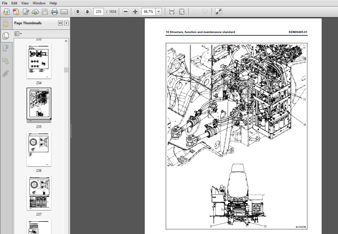
Brake system SEN00405-01
Brake system 2
Brake piping diagram 2
Brake 4
Brake valve 8
Accumulator charge valve 16
EPC relief valve 22
Accumulator (for brake) 24
Slack adjuster 26
Parking brake 30
Parking brake solenoid valve 32
Emergency parking brake release valve 34
Brake cooling pump 35
Undercarriage and frame SEN00406-00
Undercarriage and frame 2
Axle mount 2
Center hinge pin 7
Hydraulic system, Part 1 SEN00407-01
Hydraulic system, Part 1 2
Hydraulic piping diagram 2
Work equipment control lever linkage 4
Hydraulic tank 6
Work equipment hydraulic pump 8
Hydraulic system, Part 2 SEN02456-00
Hydraulic system, Part 2 2
Control valve 2
CLSS 16
Each function and operation of each valve 21
Accumulator (for PPC circuit) 36
Triple pump 37
Work equipment SEN00408-01
Work equipment 2
Work equipment linkage 2
Bucket 6
Bucket positioner and boom kick-out 8
Work equipment lubrication 9
Cab and its attachments SEN00409-01
Cab and its attachments 2
ROPS cab 2
SEN00398-05 00 Index and foreword
6 WA600-6
Air conditioner 4
Electrical system, Part 1 SEN01009-01
Electrical system, Part 1 2
Machine monitor system 2
Machine monitor 8
Electrical system, Part 2 SEN00410-02
Electrical system, Part 2 2
Work equipment control system 2
Transmission controller system 38
Electrical system, Part 3 SEN00411-02
Electrical system, Part 3 2
Electric transmission control 2
Engine starting/stopping circuit 4
Parking brake circuit 7
Sensor 11
VHMS controller related 33
Work equipment electric lever 37
20 Standard value table
Standard service value table SEN00552-01
Standard service value table 2
Standard service value table for engine 2
Standard service value table for chassis 3
30 Testing and adjusting
Testing and adjusting, Part 1 SEN00553-01
Testing and adjusting, Part 1 3
Tools for testing, adjusting, and troubleshooting 3
Measuring engine speed 6
Measuring exhaust gas color 8
Measuring exhaust temperature 9
Adjusting valve clearance 11
Testing compression pressures 13
Measuring blow-by pressure 16
Measuring engine oil pressure 17
Measuring intake air (boost) pressure 18
Handling fuel system equipment 19
Releasing residual pressure in fuel system 19
Testing fuel pressures 20
Testing return rate and leakage 21
Bleeding air from fuel circuit 24
Testing leakage in fuel system 25
Handling reduced cylinder mode operation 26
Handling no-injection cranking operation 26
Handling controller voltage circuit 27
Replacing and adjusting alternator and air conditioner compressor belt tension 28
Adjusting modulation clutch speed sensor and speed sensor 29
Measuring directional lever (Steering wheel specification) 31
Testing and adjusting power train oil pressure 32
Flushing procedure for torque converter and transmission hydraulic circuit 46
Method of moving machine when transmission valve is broken 48
Adjusting steering stop valve 50
Testing and adjusting, Part 2 SEN00554-01
Testing and adjusting, Part 2 3
Measuring operating effort of AJSS lever (AJSS specification) 3
Testing and adjusting AJSS lever angle sensor and frame angle sensor (AJSS specification) 4
00 Index and foreword SEN00398-05
WA600-6 7
Testing and adjusting steering stopper bolt (AJSS specification) 6
Testing and adjusting steering wheel (Steering wheel specification) 8
Testing steering oil pressure 10
Bleeding air from steering cylinder circuit 14
Testing hydraulic drive fan 15
Bleeding air from hydraulic drive fan circuit 18
Measuring brake pedal 20
Measuring brake performance 21
Testing and adjusting accumulator charge pressure 22
Testing wheel brake oil pressure 24
Measuring wear of wheel brake disc 26
Bleeding air from wheel brake circuit 27
Releasing residual pressure in brake accumulator circuit 28
Testing parking brake performance 29
Measuring parking brake oil pressure 30
Testing wear of parking brake disc 33
Method of releasing parking brake manually 34
Measuring and adjusting work equipment control lever 35
Measuring work equipment oil pressure 36
Bleeding air from work equipment circuit 41
Releasing residual pressure in work equipment circuit 42
Moving machine for removing operator cab 43
Testing and adjusting bucket positioner 45
Testing and adjusting lift arm position detecting lever 47
Checking proximity switch operation indication lamp 48
Preparations for work on troubleshooting of electric system 49
Procedure for testing diodes 53
Testing and adjusting, Part 3 SEN00555-01
Testing and adjusting, Part 3 2
Special functions of machine monitor (EMMS) 4
Testing and adjusting, Part 4 SEN00556-01
Testing and adjusting, Part 4 2
Special functions of machine monitor (EMMS) 2
VHMS controller initial setting procedure 15
Precautions for replacing VHMS controller 35
Pm-click inspection table 41
40 Troubleshooting
General information on troubleshooting SEN00557-00
General information on troubleshooting 2
Points to remember when troubleshooting 2
Sequence of events in troubleshooting 3
Testing before troubleshooting 4
Classification and procedures of troubleshooting 5
Connection table for connector pin numbers 8
T-branch box and T-branch adapter table 31
Troubleshooting by failure code (Display of code), Part 1 SEN00558-01
Troubleshooting by failure code (Display of code), Part 1 3
Failure codes list 3
Before carrying out troubleshooting for electrical system 16
Information contained in troubleshooting table 18
Failure code [1500L0] (TORQFLOW transmission : Double meshing) 20
Failure code [15B0NX] (Transmission filter: Clogged) 22
Failure code [15SAL1] (ECMV F clutch: When command current is OFF, fill signal is ON) 24
Failure code [15SALH] (ECMV F clutch: When command current is ON, fill signal is OFF) 26
Failure code [15SBL1] (ECMV R clutch: When command current is OFF, fill signal is ON) 28
Failure code [15SBLH] (ECMV R clutch: When command current is ON, fill signal is OFF) 30
SEN00398-05 00 Index and foreword
8 WA600-6
Failure code [15SEL1] (ECMV (1): When command current is OFF, fill signal is ON) 32
Failure code [15SELH] (ECMV (1): When command current is ON, fill signal is OFF) 34
Failure code [15SFL1] (ECMV (2): When command current is OFF, fill signal is ON) 36
Failure code [15SFLH] (ECMV (2): When command current is ON, fill signal is OFF) 38
Failure code [15SGL1] (ECMV (3): When command current is OFF, fill signal is ON) 40
Failure code [15SGLH] (ECMV (3): When command current is ON, fill signal is OFF) 42
Failure code [15SHL1] (ECMV (4): When command current is OFF, fill signal is ON) 44
Failure code [15SHLH] (ECMV (4): When command current is ON, fill signal is OFF) 46
Failure code [15W0NT] (Transmission modulation clutch: Overheating) 48
Failure code [2F00MA] (Parking brake: Malfunction) 49
Failure code [2G42ZG] (Front accumulator: Low oil pressure) 52
Troubleshooting by failure code (Display of code), Part 2 SEN00559-01
Troubleshooting by failure code (Display of code), Part 2 4
Failure code [2G43ZG] (Rear accumulator: Low oil pressure) 4
Failure code [44K0L4] (Bucket positioner: ON/OFF signals disagree) 6
Failure code [A000N1] (or VHMS_LED display: “n2” o “01”) (Engine: Overrun) 8
Failure code [AA1ANX] (Air cleaner: Clogging) 10
Failure code [AB00L6] (Alternator: Signal disagrees with operating state of engine) 12
Failure code [AB00MA] (Alternator: Malfunction) 14
Failure code [B@BAZG] (Rotation derating by low engine oil pressure) 16
Failure code [B@BAZK] (Engine oil: Low level) 18
Failure code [B@BCNS] (Engine overheating) 20
Failure code [B@BCZK] (Coolant: Low level) 22
Failure code [B@C7NS] (Brake oil: Overheating) 24
Failure code [B@CENS] (Torque converter oil: Overheating) 26
Failure code [B@GAZK] (Battery electrolyte: Low level) 28
Failure code [B@HANS] (Hydraulic oil: Overheating) 30
Failure code [CA111] (Abnormality in engine controller) 32
Failure code [CA115] (Engine Ne or Bkup speed sensor error) 34
Failure code [CA122] (Charge pressure sensor high error) 36
Failure code [CA123] (Charge pressure sensor low error) 38
Failure code [CA131] (Throttle sensor high error) 40
Failure code [CA132] (Throttle sensor low error) 42
Failure code [CA135] (Engine oil pressure sensor high error) 44
Failure code [CA141] (Engine oil pressure sensor low error) 46
Failure code [CA144] (Coolant temperature sensor high error) 48
Failure code [CA145] (Coolant temperature sensor low error) 50
Failure code [CA153] (Charge temperature sensor high error) 52
Failure code [CA154] (Charge temperature sensor low error) 54
Failure code [CA187] (Sensor power supply 2 low error) 55
Failure code [CA212] (Engine oil temperature sensor high error) 56
Failure code [CA213] (Engine oil temperature sensor low error) 58
Failure code [CA221] (Atmospheric pressure sensor high error) 60
Failure code [CA222] (Atmospheric pressure sensor low error) 62
Failure code [CA227] (Sensor power supply 2 high error) 64
Troubleshooting by failure code (Display of code), Part 3 SEN00560-00
Troubleshooting by failure code (Display of code), Part 3 3
Failure code [CA234] (Engine overspeed) 3
Failure code [CA238] (Ne speed sensor power supply error) 4
Failure code [CA263] (Fuel temperature sensor high error) 6
Failure code [CA265] (Fuel temperature sensor low error) 8
Failure code [CA271] (PCV1 Short circuit) 10
Failure code [CA272] (PCV1 Disconnection) 12
Failure code [CA273] (PCV2 Short circuit) 14
Failure code [CA274] (PCV2 Disconnection) 16
Failure code [CA322] (Injector #1 (L/B #1) open/short error) 18
Failure code [CA323] (Injector #5 (L/B #5) open/short error) 20
00 Index and foreword SEN00398-05
WA600-6 9
Failure code [CA324] (Injector #3 (L/B #3) open/short error) 22
Failure code [CA325] (Injector #6 (L/B #6) open/short error) 24
Failure code [CA331] (Injector #2 (L/B #2) open/short error) 26
Failure code [CA332] (Injector #4 (L/B #4) open/short error) 28
Failure code [CA342] (Calibration code inconsistency) 30
Failure code [CA351] (Injectors drive circuit error) 32
Failure code [CA352] (Sensor power supply 1 low error) 34
Failure code [CA386] (Sensor power supply 1 high error) 36
Failure code [CA431] (Idle validation switch error) 38
Failure code [CA432] (Idle validation action error) 40
Failure code [CA441] (Battery voltage low error) 40
Failure code [CA442] (Battery voltage high error) 41
Failure code [CA449] Common rail pressure high error 2 41
Failure code [CA451] (Common rail pressure sensor high error) 42
Failure code [CA452] (Common rail pressure sensor low error) 44
Failure code [CA553] (Common rail pressure high error 1) 45
Failure code [CA559] (Supply pump pressure very low error) 46
Failure code [CA689] (Engine Ne speed sensor error) 50
Failure code [CA731] (Engine Bkup speed sensor phase error) 52
Failure code [CA757] (All continuous data lost error) 53
Failure code [CA778] (Engine Bkup speed sensor error) 54
Failure code [CA1228] (EGR valve servo error 1) 56
Failure code [CA1625] (EGR valve servo error 2) 57
Failure code [CA1626] (Bypass valve solenoid current high error) 58
Failure code [CA1627] (Bypass valve solenoid current low error) 60
Failure code [CA1628] (Bypass valve servo error 1) 61
Failure code [CA1629] (Bypass valve servo error 2) 62
Failure code [CA1631] (Bypass valve lift sensor high error) 64
Failure code [CA1632] (Bypass valve lift sensor low error) 66
Failure code [CA1633] (KOMNET datalink timeout error) 67
Troubleshooting by failure code (Display of code), Part 4 SEN00561-01
Troubleshooting by failure code (Display of code), Part 4 4
Failure code [CA2185] (Throttle sensor supply voltage high error) 4
Failure code [CA2186] (Throttle sensor power supply low error) 6
Failure code [CA2249] (Supply pump pressure very low error 2) 7
Failure code [CA2271] (EGR valve lift sensor high error) 8
Failure code [CA2272] (EGR valve lift sensor low error) 10
Failure code [CA2351] (EGR valve solenoid operation short circuit) 12
Failure code [CA2352] (EGR valve solenoid operation disconnect) 14
Failure code [CA2555] (Intake heater relay voltage low error) 15
Failure code [CA2556] (Intake heater relay voltage high error) 16
Failure code [D191KA] (AJSS neutral safety relay: Disconnection) 18
Failure code [D191KB] (AJSS neutral safety relay: Short circuit) 20
Failure code [D192KA] (ECSS solenoid: Disconnection) 22
Failure code [D192KB] (ECSS solenoid: Short circuit) 23
Failure code [D192KY] (ECSS solenoid: Short circuit with power supply line) 24
Failure code [D198KA] (Transmission oil pressure bypass solenoid: Disconnection) 25
Failure code [D198KB] (Transmission oil pressure bypass solenoid: Short circuit) 26
Failure code [D198KY] (Transmission oil pressure bypass solenoid:
Short circuit with power supply line) 27
Failure code [D5ZHKA] (Terminal C signal: Disconnection) 28
Failure code [D5ZHKB] (Terminal C signal: Short circuit) 30
Failure code [D5ZHKZ] (Terminal C signal: Disconnection or short circuit) 32
Failure code [D5ZHL6] (Terminal C signal: Signal does not match engine running or
stopped state) 34
Failure code [DA80L4] (Auto grease controller: ON/OFF signals disagree) 36
Failure code [DAF3KK] (Machine monitor: Low source voltage (input)) 38
Failure code [DAF5KP] (Machine monitor: Low output voltage) 40
SEN00398-05 00 Index and foreword
10 WA600-6
Failure code [DAFRKR] (CAN communication with machine monitor:
Defective communication (Abnormality in target component system)) 42
Failure code [DAQ0KK] (Transmission controller: Low source voltage) 44
Failure code [DAQ0KT] (Transmission controller: Abnormality in controller) 46
Failure code [DAQ2KK] (Transmission controller load power supply line:
Low source voltage (input)) 48
Failure code [DAQ9KQ] (Transmission controller model selection:
Disagreement of model selection signals) 50
Failure code [DAQRKR] (CAN communication with transmission controller:
Defective communication (Abnormality in target component system)) 52
Failure code [DAQRMA] (Transmission controller CAN communication: Malfunction) 54
Troubleshooting by failure code (Display of code), Part 5 SEN00562-01
Troubleshooting by failure code (Display of code), Part 5 4
Failure code [DB2RKR] CAN communication from engine controller:
Defective communication (Abnormality in target component system) 4
Failure code [DB90KK] Work equipment controller: Low source voltage (input) 6
Failure code [DB90KT] (Work equipment controller: Abnormality in controller) 8
Failure code [DB92KK] Work equipment controller load power supply line:
Low source voltage (input) 10
Failure code [DB95KX] (Work equipment controller power supply output:
Out of input signal range) 12
Failure code [DB99KQ] (Work equipment controller model selection:
Disagreement of model selection signals) 14
Failure code [DB9RKR] CAN communication with work equipment controller:
Defective communication (Abnormality in target component system) 16
Failure code [DB9RMA] (Work equipment controller CAN communication: Malfunction) 18
Failure code [DB9RMC] (CAN communication with transmission controller:
Defective operation) 20
Failure code [DBB0KK] (or VHMS_LED display: “n9” o “01”) VHMS controller:
Low source voltage (input) 22
Failure code [DBB0KQ] (or VHMS_LED display: “nF” o “11”) VHMS controller:
(Disagreement of model selection signals) 24
Failure code [DBB3KK] (or VHMS_LED display: “n9” o “05”) VHMS controller
battery power supply: Low source voltage (input) 26
Failure code [DBB5KP] (or VHMS_LED display: “n9” o “04”) (VHMS controller
5 V power supply output: Low output voltage) 28
Failure code [DBB6KP] (or VHMS_LED display: “n9” o “02”) (VHMS controller
24 V power supply output: Low output voltage) 30
Failure code [DBB7KP] (or VHMS_LED display: “n9” o “03”) (VHMS controller
12 V power supply output: Low output voltage) 32
Failure code [DBBQKR] (or VHMS_LED display: “n8” o “02”) VHMS controller CAN
communication: Defective communication (Abnormality in target component system) 34
Failure code [DD15LD] (t switch (Panel switch 1): Switch is kept pressed for long time) 36
Failure code [DD16LD] (U switch (Panel switch 2): Switch is kept pressed for long time) 38
Failure code [DD17LD] (< switch (Panel switch 3): Switch is kept pressed for long time) 40
Failure code [DD18LD] (> switch (Panel switch 4): Switch is kept pressed for long time) 42
Failure code [DD1ALD] (Remote positioner raise/lower set switch (raise):
Switch is kept pressed for long time) 44
Failure code [DD1BLD] (Remote positioner raise/lower set switch (lower):
Switch is kept pressed for long time) 46
Failure code [DD1CLD] (Load meter subtotal switch: Switch is kept pressed for long time) 48
Failure code [DD1FLD] (Load meter mode selector switch (A/B): Switch is kept
pressed for long time) 50
Failure code [DD1GLD] (Load meter mode selector switch (+/–): Switch is kept
pressed for long time) 52
Troubleshooting by failure code (Display of code), Part 6 SEN00569-01
Troubleshooting by failure code (Display of code), Part 6 4
00 Index and foreword SEN00398-05
WA600-6 11
Failure code [DD1HLD] (Load meter display selector switch: Switch is kept pressed
for long time) 4
Failure code [DDA7L4] (RPM set ON/OFF switch: ON-OFF signals disagree 6
Failure code [DDA8KB] (RPM set idle-up/down selector switch (idle-up): Short circuit) 8
Failure code [DDA9KB] (RPM set idle-up/down selector switch (idle-down): Short circuit) 10
Failure code [DDB6L4] (Turn parking brake switch (Neutralizer): ON/OFF signals disagree) 12
Failure code [DDD1LD] (Remote positioner bucket angle set switch: Switch is kept
pressed for long time) 16
Failure code [DDDBKA] (Traction adjustment dial: Disconnection) 18
Failure code [DDDBKB] (Traction adjustment dial: Short circuit) 20
Failure code [DDE5MA] (Emergency steering drive switch: Malfunction) 22
Failure code [DDK4KA] (AJSS FNR switch: Disconnection) 24
Failure code [DDK4KB] (AJSS FNR switch: Short circuit) 26
Failure code [DDK5L4] (AJSS shit-up/down switch: ON/OFF signals disagree) 28
Failure code [DDK6KA] (FNR lever switch: Disconnection) 32
Failure code [DDK6KB] (FNR lever switch: Short circuit) 34
Failure code [DDP5KA] (Lock detection pressure switch of steering lock lever: Disconnection)36
Failure code [DDT0L4] (Shift mode selector switch: ON/OFF signals disagree) 38
Failure code [DDW9LD] (Kick-down switch: Switch is kept pressed for long time) 40
Failure code [DDWLLD] (Hold switch: Switch is kept pressed for long time) 42
Failure code [DDY0LD] (Load meter cancel switch: Switch is kept pressed for long time) 44
Failure code [DF10KA] (Transmission shift lever switch: Disconnection) 46
Failure code [DF10KB] (Transmission shift lever switch: Short circuit) 48
Failure code [DGE5KX] (or VHMS_LED display: “n4” o “01”) (Atmospheric temperature
sensor: Out of input signal range) 50
Failure code [DGF1KA] (Transmission oil temperature sensor: Disconnection) 52
Failure code [DGF1KB] (Transmission oil temperature sensor: Short circuit) 54
Troubleshooting by failure code (Display of code), Part 7 SEN00570-01
Troubleshooting by failure code (Display of code), Part 7 4
Failure code [DGH2KX] (Hydraulic oil temperature sensor: Out of input signal range) 4
Failure code [DGR2KA] (Rear brake oil temperature sensor: Disconnection) 6
Failure code [DGR2KX] (Rear brake oil temperature sensor: Out of input signal range) 8
Failure code [DGT1KA] (Torque converter oil temperature sensor: Disconnection) 10
Failure code [DGT1KB] (Torque converter oil temperature sensor: Short circuit) 11
Failure code [DGT1KX] (Torque converter oil temperature sensor: Out of input signal
range) 12
Failure code [DGT4KA] (or VHMS_LED display: “n3” o “12”) (Exhaust gas temperature
sensor (F): Disconnection) 14
Failure code [DGT4KB] (or VHMS_LED display: “n3” o “11”) (Exhaust gas temperature
sensor (F): Short circuit) 16
Failure code [DGT5KA] (or VHMS_LED display: “n3” o “22”) (Exhaust gas temperature
sensor (R): Disconnection) 18
Failure code [DGT5KB] (or VHMS_LED display: “n3” o “21”) (Exhaust gas temperature
sensor (R): Short circuit) 20
Failure code [DH21KA] (Work equipment pump oil pressure sensor: Disconnection) 22
Failure code [DH21KB] (Work equipment pump oil pressure sensor: Short circuit) 24
Failure code [DHE5KB] (or VHMS_LED display: “n3” o “32”) (Blow-by pressure sensor:
Short circuit) 26
Failure code [DHE5KY] (or VHMS_LED display: “n3” o “31”) (Blow-by pressure sensor:
Short circuit with power supply line) 28
Failure code [DHPCKX] (Lift arm cylinder bottom pressure sensor: Out of input signal
range) 30
Failure code [DHPDKX] (Lift arm cylinder head pressure sensor: Out of input signal
range) 32
Failure code [DHT2L6] (Transmission filter clogging sensor: Signal disagrees with
operating state of engine) 34
Failure code [DHT8KX] (or VHMS_LED display: “n5” o “33”) (Steering oil pressure sensor:
Out of input signal range) 36
SEN00398-05 00 Index and foreword
12 WA600-6
Failure code [DHTBKA] (Modulation clutch oil pressure sensor: Disconnection) 38
Failure code [DHTBKB] (Modulation clutch oil pressure sensor: Short circuit) 40
Failure code [DHU2KX] (or VHMS_LED display: “n7” o “11”) (Front brake oil pressure
sensor (F): Out of input signal range) 42
Failure code [DHU3KX] (or VHMS_LED display: “n7” o “12”) (Rear brake oil pressure
sensor (R): Out of input signal range) 44
Failure code [DK30KA] (AJSS lever angle sensor: Disconnection) 46
Failure code [DK30KY] (AJSS lever angle sensor: Short circuit with power supply line) 48
Troubleshooting by failure code (Display of code), Part 8 SEN00571-01
Troubleshooting by failure code (Display of code), Part 8 3
Failure code [DK59KA] (Lift arm EPC lever potentiometer (Main): Disconnection) 3
Failure code [DK59KY] (Lift arm EPC lever potentiometer (Main): Short circuit with
power supply line) 6
Failure code [DK59L8] (Lift arm EPC lever potentiometer (Main): Analog signals disagree) 10
Failure code [DK5AKA] (Lift arm EPC lever potentiometer (Sub): Disconnection) 13
Failure code [DK5AKY] (Lift arm EPC lever potentiometer (Sub): Short circuit with
power supply line) 16
Failure code [DK5BKA] (Bucket EPC lever potentiometer (Main): Disconnection) 19
Failure code [DK5BKY] (Bucket EPC lever potentiometer (Main): Short circuit with
power supply line) 22
Failure code [DK5BL8] (Bucket EPC lever potentiometer (Main): Analog signals disagree) 24
Failure code [DK5CKA] (Bucket EPC lever potentiometer (Sub): Disconnection) 27
Failure code [DK5CKY] (Bucket EPC lever potentiometer (Sub): Short circuit with
power supply line) 30
Failure code [DK5DKA] (3-spool valve (attachment) EPC lever potentiometer (Main):
Disconnection) 32
Failure code [DK5DKY] (3-spool valve (attachment) EPC lever potentiometer (Main):
Short circuit with power supply line) 34
Failure code [DK5DL8] (3-spool valve (attachment) EPC lever potentiometer (Main):
Analog signals disagree) 36
Failure code [DK5EKA] (3-spool valve (attachment) EPC lever potentiometer (Sub):
Disconnection) 40
Failure code [DK5EKY] (3-spool valve EPC lever potentiometer (Sub): Short circuit with
power supply line) 42
Failure code [DKA0KA] (Lift arm angle sensor: Disconnection) 44
Failure code [DKA0KX] (Lift arm angle sensor: Out of input signal range) 46
Failure code [DKA0KY] (Lift arm angle sensor: Short circuit with power supply line) 48
Failure code [DKA0L0] (Lift arm angle sensor: Improper position) 50
Troubleshooting by failure code (Display of code), Part 9 SEN00572-01
Troubleshooting by failure code (Display of code), Part 9 4
Failure code [DKD0KA] (Frame angle sensor: Disconnection) 4
Failure code [DKD0KY] (Frame angle sensor: Short circuit with power supply line) 6
Failure code [DKD0KZ] (AJSS lever and frame angle sensor: Disconnection or short circuit) 8
Failure code [DLFAKA] (Modulation clutch output shaft speed sensor: Disconnection) 10
Failure code [DLFALC] (Modulation clutch output shaft speed sensor: Speed signals
disagree) 12
Failure code [DLT3KA] (Transmission output shaft speed sensor (2): Disconnection) 14
Failure code [DLT3LC] (Transmission output shaft speed sensor (2): Speed signals disagree) 16
Failure code [DLT4KB] (Transmission output shaft speed sensor (1): Short circuit) 18
Failure code [DLT4KX] (Transmission output shaft speed sensor (1): Out of input signal
range) 20
Failure code [DUM1KB] (Remote positioner raise indicator lamp: Short circuit) 22
Failure code [DUM2KB] (Remote positioner lower indicator lamp: Short circuit) 24
Failure code [DV00KB] (Alarm buzzer: Short circuit) 26
Failure code [DW4PKA] (Lift arm raise EPC solenoid: Disconnection) 28
Failure code [DW4PKB] (Lift arm raise EPC solenoid: Short circuit) 29
Failure code [DW4PKY] (Lift arm raise EPC solenoid: Short circuit with power supply line) 30
00 Index and foreword SEN00398-05
WA600-6 13
Failure code [DW4QKA] (Lift arm lower EPC solenoid: Disconnection) 32
Failure code [DW4QKB] (Lift arm lower EPC solenoid: Short circuit) 33
Failure code [DW4QKY] (Lift arm lower EPC solenoid: Short circuit with power supply line) 34
Failure code [DW4RKA] (Bucket tilt EPC solenoid: Disconnection) 36
Failure code [DW4RKB] (Bucket tilt EPC solenoid: Short circuit) 37
Failure code [DW4RKY] (Bucket tilt EPC solenoid: Short circuit with power supply line) 38
Failure code [DW4SKA] (Bucket dump EPC solenoid: Disconnection) 40
Failure code [DW4SKB] (Bucket dump EPC solenoid: Short circuit) 41
Failure code [DW4SKY] (Bucket dump EPC solenoid: Short circuit with power supply line) 42
Failure code [DW7BKA] (Fan reverse solenoid: Disconnection) 44
Failure code [DW7BKB] (Fan reverse solenoid: Short circuit) 46
Failure code [DW7BKY] (Fan reverse solenoid: Short circuit with power supply line) 48
Failure code [DW7DKA] (Hydraulic drive fan neutral solenoid: Disconnection) 50
Failure code [DW7DKB] (Hydraulic drive fan neutral solenoid: Short circuit) 50
Failure code [DW7DKY] (Hydraulic drive fan neutral solenoid: Short circuit with
power supply line) 51
Troubleshooting by failure code (Display of code), Part 10 SEN00573-01
Troubleshooting by failure code (Display of code), Part 10 4
Failure code [DWM1KA] (Work equipment neutral lock solenoid: Disconnection) 4
Failure code [DWM1KB] (Work equipment neutral lock solenoid: Short circuit) 6
Failure code [DWM1KY] (Work equipment neutral lock EPC solenoid: Short circuit with
power supply line) 8
Failure code [DWN6KA] (Lift arm raise magnet detent solenoid: Disconnection) 10
Failure code [DWN6KB] (Lift arm raise magnet detent solenoid: Short circuit) 12
Failure code [DWN6KY] (Lift arm raise magnet detent solenoid: Short circuit with power
supply line) 14
Failure code [DWN7KA] (Lift arm float magnet detent solenoid: Disconnection) 16
Failure code [DWN7KB] (Lift arm float magnet detent solenoid: Short circuit) 18
Failure code [DWN7KY] (Lift arm float magnet detent solenoid: Short circuit with power
supply line) 20
Failure code [DWN8KA] (Bucket tilt magnet detent solenoid: Disconnection) 22
Failure code [DWN8KB] (Bucket tilt magnet detent solenoid: Short circuit) 24
Failure code [DWN8KY] (Bucket tilt magnet detent solenoid: Shorted with the power source) 26
Failure code [DWNFKA] (Modulation clutch cut-off release solenoid: Disconnection) 28
Failure code [DWNFKB] (Modulation clutch cut-off release solenoid: Short circuit) 30
Failure code [DWNFKY] (Modulation clutch cut-off release solenoid: Short circuit with
power source line) 32
Failure code [DX16KA] (Fan pump EPC solenoid: Disconnection) 34
Failure code [DX16KB] (Fan pump EPC solenoid: Short circuit) 35
Failure code [DX16KY] (Fan pump EPC solenoid: Short circuit with power supply line) 36
Failure code [DXA1KA] (Pump PC-EPC solenoid: Disconnection) 37
Failure code [DXA1KB] (Pump PC-EPC solenoid: Short circuit) 38
Failure code [DXF0KA] (AJSS EPC solenoid: Disconnection) 39
Failure code [DXF0KB] (AJSS EPC solenoid: Short circuit) 40
Failure code [DXH1KA] (Lockup ECMV solenoid: Disconnection) 41
Failure code [DXH1KB] (Lockup ECMV solenoid: Short circuit) 42
Failure code [DXH1KY] (Lockup ECMV solenoid: Short circuit with power supply line) 44
Failure code [DXH4KA] (1st clutch ECMV solenoid: Disconnection) 46
Failure code [DXH4KB] (1st clutch ECMV solenoid: Short circuit) 48
Failure code [DXH4KY] (1st clutch ECMV solenoid: Short circuit with power supply line) 50
Troubleshooting by failure code (Display of code), Part 11 SEN00574-01
Troubleshooting by failure code (Display of code), Part 11 4
Failure code [DXH5KA] (2nd clutch ECMV solenoid: Disconnection) 4
Failure code [DXH5KB] (2nd clutch ECMV solenoid: Short circuit) 6
Failure code [DXH5KY] (2nd clutch ECMV solenoid: Short circuit with power supply line) 8
Failure code [DXH6KA] (3rd clutch ECMV solenoid: Disconnection) 10
Failure code [DXH6KB] (3rd clutch ECMV solenoid: Short circuit) 12
SEN00398-05 00 Index and foreword
14 WA600-6
Failure code [DXH6KY] (3rd clutch ECMV solenoid: Short circuit with power supply line) 14
Failure code [DXH7KA] (R clutch ECMV solenoid: Disconnection) 16
Failure code [DXH7KB] (R clutch ECMV solenoid: Short circuit) 18
Failure code [DXH7KY] (R clutch ECMV solenoid: Short circuit with power supply line) 20
Failure code [DXH8KA] (F clutch ECMV solenoid: Disconnection) 22
Failure code [DXH8KB] (F clutch ECMV solenoid: Short circuit) 24
Failure code [DXH8KY] (F clutch ECMV solenoid: Short circuit with power supply line) 26
Failure code [DXHHKA] (4th clutch ECMV solenoid: Disconnection) 28
Failure code [DXHHKB] (4th clutch ECMV solenoid: Short circuit) 30
Failure code [DXHHKY] (4th clutch ECMV solenoid: Short circuit with power supply line) 32
Failure code [DXHJKA] (3-spool valve extract EPC solenoid: Disconnection) 34
Failure code [DXHJKB] (3-spool valve extract EPC solenoid: Short circuit) 35
Failure code [DXHJKY] (3-spool valve extract EPC solenoid: Short circuit with power
supply line) 36
Failure code [DXHKKA] (3-spool valve retract EPC solenoid: Disconnection) 37
Failure code [DXHKKB] (3-spool valve retract EPC solenoid: Short circuit) 38
Failure code [DXHKKY] (3-spool valve retract EPC solenoid: Short circuit with power
supply line) 39
Failure code [DXHPKA] (Modulation clutch solenoid: Disconnection) 40
Failure code [DXHPKB] (Modulation clutch solenoid: Short circuit) 42
Failure code [DXHPKY] (Modulation clutch solenoid: Short circuit with power source line) 44
Failure code [DXHPMA] (Modulation clutch solenoid: Malfunction) 46
Failure code [F@BBZL] (or VHMS_LED display: “n3” o “38”) (Blow-by pressure: High error) 48
Failure code [F@BYNR] (or VHMS_LED display: “n3” o “62”)
(Exhaust gas temperature (F): Abnormal heat) 50
Failure code [F@BYNS] (or VHMS_LED display: “n3” o “61”)
(Exhaust gas temperature (F): Overheat) 52
Failure code [F@BZNR] (or VHMS_LED display: “n3” o “72”)
(Exhaust gas temperature (R): abnormal heat) 54
Failure code [F@BZNS] (or VHMS_LED display “n3” o “71”)
(Exhaust gas temperature (R): Overheat) 56
Troubleshooting of electrical system (E-mode) SEN00563-01
Troubleshooting of electrical system (E-mode) 4
Before carrying out troubleshooting of electrical system 4
Information in troubleshooting table 7
E-1 Engine does not start 8
E-2 Wiper does not operate 18
E-3 Windshield washer does not operate 26
E-4 Headlamp, clearance lamp, tail lamp, and license lamp do not light up or go off 32
E-5 Working lamp does not light up or go off 46
E-6 Step lamp does not light up or go off 52
E-7 Turn signal lamp and hazard lamp do not light up or go off 54
E-8 Brake lamp does not light or it keeps lighting up 64
E-9 Backup lamp does not light or it keeps lighting up 66
E-10 Backup buzzer does not sound or it keeps sounding 70
E-11 Horn does not sound or it keeps sounding 74
E-12 Alarm buzzer does not sound or it keeps sounding 78
E-13 Air conditioner does not operate or stop 80
Troubleshooting of hydraulic and mechanical system (H-mode) SEN00564-00
Troubleshooting of hydraulic and mechanical system (H-mode) 4
Method of using troubleshooting chart 4
Table of failure modes and causes 6
H-1 Machine does not start 10
H-2 Torque converter lockup is not switched (engine stalls) 12
H-3 Torque converter lockup is not turned on 13
H-4 Travel speed is slow, thrusting force is weak, uphill traveling power is weak,
and gear is not shifted 14
00 Index and foreword SEN00398-05
WA600-6 15
H-5 Shocks are large at the times of starting and shifting gear 16
H-6 Time lag is large at the times of starting and shifting gear 18
H-7 Torque converter oil temperature is high 20
H-8 Steering does not turn [machine with steering wheel] 21
H-9 Steering does not turn [machine with AJSS] 22
H-10 Turning, response of steering is poor [machine with steering wheel] 23
H-11 Turning, response of AJSS is poor [machine with AJSS] 24
H-12 Steering is heavy [machine with steering wheel] 25
H-13 When machine turns, it shakes or makes large shocks [machine with steering wheel] 26
H-14 When machine turns, it shakes or makes large shocks [machine with AJSS] 27
H-15 Wheel brake does not work or does not work well 28
H-16 Wheel brake is not released or it drags 29
H-17 Parking brake does not work or does not work well 30
H-18 Parking brake is not released or it drags (including emergency release system) 31
H-19 Lift arm does not rise 32
H-20 Lift arm speed is low or rising force of lift arm is insufficient 33
H-21 When rising, lift arm comes to move slowly at specific height 34
H-22 Lift arm cylinder cannot hold down bucket (Bucket floats) 34
H-23 Hydraulic drifts of lift arm occur often 34
H-24 Lift arm wobbles during operation 34
H-25 Bucket does not tilt back 35
H-26 Bucket speed is low or tilting back force is insufficient 36
H-27 Bucket comes to operate slowly in the midst of tilting-back 37
H-28 Bucket cylinder cannot hold down bucket 37
H-29 Hydraulic drifts of bucket occur often 37
H-30 Bucket wobbles during travel with cargo (Work equipment valve is set to “HOLD”) 37
H-31 During operation of machine, engine speed lowers remarkably or engine stalls 38
H-32 Large shocks are made when work equipment starts and stops 38
H-33 When work equipment circuit is relieved singly, other work equipment moves 38
H-34 ECSS does not operate, and pitching bouncing occurs 39
Troubleshooting of engine (S-mode) SEN00565-00
Troubleshooting of engine (S-mode) 3
Method of using troubleshooting chart 3
S-1 Engine does not start easily 6
S-2 Engine does not start 8
S-3 Engine does not pick up smoothly 12
S-4 Engine stops during operation 13
S-5 Engine does not rotate smoothly 14
S-6 Engine lacks output (or lacks power) 15
S-7 Exhaust smoke is black (Incomplete combustion) 16
S-8 Oil is consumed much (or exhaust gas color is blue) 18
S-9 Engine oil becomes contaminated quickly 19
S-10 Fuel consumption is excessive 20
S-11 Coolant contains oil (blows back or reduces) 21
S-12 Oil pressure drops 22
S-13 Oil level rises (Water, fuel in oil) 24
S-14 Coolant temperature rises too high (Overheating) 26
S-15 Abnormal noise is made 27
S-16 Vibration is excessive 28
50 Disassembly and assembly
General information on disassembly and assembly SEN01156-01
General information on disassembly and assembly 2
How to read this manual 2
Coating materials list 4
Special tool list 7
Sketches of special tools 11
SEN00398-05 00 Index and foreword
16 WA600-6
Engine and cooling system, Part 1 SEN01157-00
Engine and cooling system, Part 1 2
Removal and installation of engine assembly 2
Removal and installation of radiator assembly 6
Removal and installation of air aftercooler 11
Removal and installation of cooling fan and fan motor assembly 12
Removal and installation of damper assembly 14
Disassembly and assembly of damper assembly 16
Removal and installation of fuel tank assembly 20
Removal and installation of engine hood assembly 22
Removal and installation of bulkhead assembly 24
Engine and cooling system, Part 2 SEN01158-00
Engine and cooling system, Part 2 2
Removal and installation of fuel supply pump assembly 2
Removal and installation of cylinder head assembly 8
Removal and installation of fuel injector assembly 24
Removal and installation of engine front seal 28
Removal and installation of engine rear seal 31
Power train, Part 1 SEN01160-00
Power train, Part 1 2
Removal and installation of parking brake assembly 2
Removal and installation of torque converter and transmission assembly 4
Power train, Part 2 SEN01162-00
Power train, Part 2 2
Disassembly and assembly of torque converter assembly 2
Disassembly and assembly of transmission assembly 29
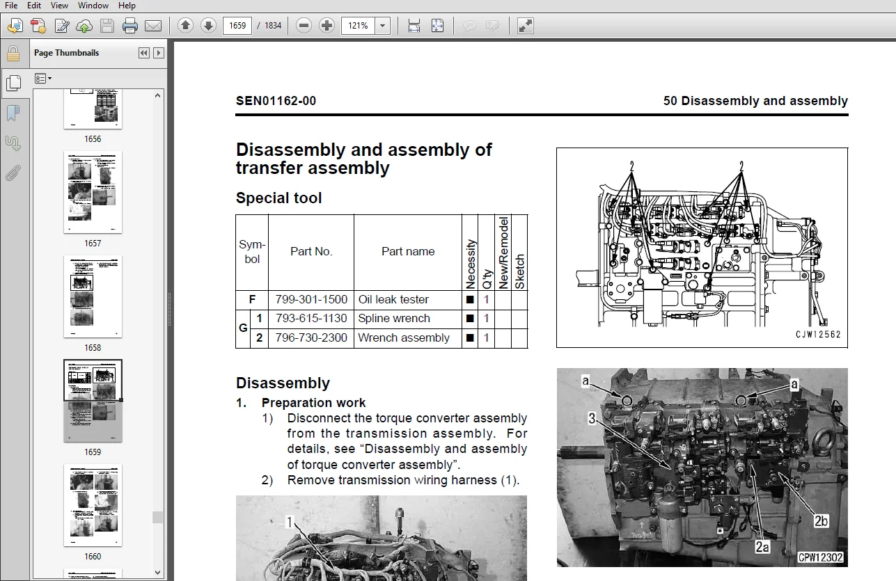
Disassembly and assembly of transfer assembly 56
Disassembly and assembly of parking brake assembly 71
Power train, Part 3 SEN01164-00
Power train, Part 3 2
Removal and installation of front axle assembly 2
Removal and installation of rear axle assembly 4
Removal and installation of center support assembly 6
Disassembly and assembly of center support assembly 8
Disassembly and assembly of differential assembly 12
Power train, Part 4 SEN01165-00
Power train, Part 4 2
Removal and installation of final drive carrier assembly 2
Disassembly and assembly of final drive carrier assembly 4
Removal and installation of front final drive brake assembly 5
Disassembly and assembly of final drive assembly 7
Brake system SEN01167-00
Brake system 2
Disassembly and assembly of brake assembly 2
Removal and installation of brake valve assembly 10
Disassembly and assembly of accumulator and charge valve assembly 11
Disassembly and assembly of slack adjustor assembly 14
Undercarriage and frame SEN01169-00
Undercarriage and frame 2
Removal and installation of center hinge pin 2
Removal and installation of counterweight assembly 9
Hydraulic system SEN01171-00
Hydraulic system 2
Removal and installation of hydraulic tank assembly 2
Removal and installation of hydraulic pump assembly 4
00 Index and foreword SEN00398-05
WA600-6 17
Removal and installation of control valve assembly 8
Disassembly and assembly of control valve assembly 10
Removal and installation of steering valve assembly 15
Removal and installation of ECSS accumulator assembly 16
Disassembly and assembly of hydraulic cylinder assembly 17
Work equipment SEN01174-00
Work equipment 2
Removal and installation of work equipment assembly 2
Cab and its attachments SEN01175-00
Cab and its attachments 2
Removal and installation of operator’s cab assembly 2
Removal and installation of operator’s cab glass (stuck glass) 6
Removal and installation of floor frame assembly 14
Electrical system SEN01177-00
Electrical system 2
Removal and installation of engine controller assembly 2
Removal and installation of transmission controller assembly 4
Removal and installation of loader controller assembly 4
Removal and installation of VHMS controller assembly 5
Removal and installation of monitor assembly 6
Removal and installation of air conditioner unit assembly 9
90 Diagrams and drawings
Hydraulic diagrams and drawings SEN00412-02
Power train hydraulic circuit diagram 2
Brake hydraulic circuit diagram 3
Work equipment hydraulic circuit diagram 5
Electrical diagrams and drawings SEN00413-02
Air conditioner electrical circuit diagram 3
Steering wheel specification
Electrical circuit diagram (1/10) 5
Electrical circuit diagram (2/10) 7
Electrical circuit diagram (3/10) 9
Electrical circuit diagram (4/10) 11
Electrical circuit diagram (5/10) 13
Electrical circuit diagram (6/10) 15
Electrical circuit diagram (7/10) 17
Electrical circuit diagram (8/10) 19
Electrical circuit diagram (9/10) 21
Electrical circuit diagram (10/10) 23
AJSS (Advanced Joystick Steering System) specification
Electrical circuit diagram (1/10) 25
Electrical circuit diagram (2/10) 27
Electrical circuit diagram (3/10) 29
Electrical circuit diagram (4/10) 31
Electrical circuit diagram (5/10) 33
Electrical circuit diagram (6/10) 35
Electrical circuit diagram (7/10) 37
Electrical circuit diagram (8/10) 39
Electrical circuit diagram (9/10) 41
Electrical circuit diagram (10/10) 43
Connector arrangement diagram 45
KOMATSU WA600-6 GALEO WHEEL LOADER SHOP MANUAL – PDF DOWNLOAD:
IMAGES PREVIEW OF THE MANUAL:
PLEASE NOTE:
- This is the SAME MANUAL used by the dealerships to diagnose your vehicle
- No waiting for couriers / posts as this is a PDF manual and you can download it within 2 minutes time once you make the payment.
- Your payment is all safe and the delivery of the manual is INSTANT – You will be taken to the DOWNLOAD PAGE.
- So have no hesitations whatsoever and write to us about any queries you may have : heydownloadss @gmail.com


