
Trusted Business
Verified & Licensed
Virus Free Files
100% Safe Downloads
Secure Payment
SSL Protected
Instant Delivery
Available Immediately
Sale!


Komatsu WA800-3EO WA900-3EO Wheel Loader Field Assembly Instruction Manual SN 70001, 60001 and up – PDF DOWNLOAD
Original price was: $42.95.$13.95Current price is: $13.95.
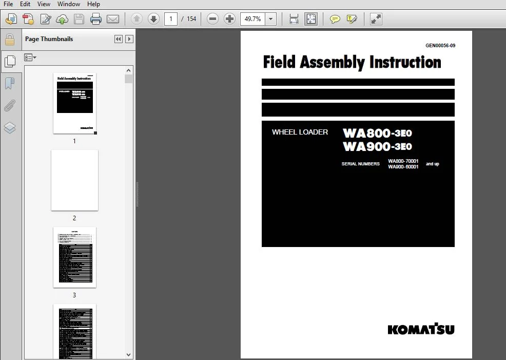
Komatsu WA800-3EO WA900-3EO Wheel Loader Field Assembly Instruction Manual
SERIAL NUMBERS
WA800-70001 and up
WA900-60001 and up
Instant PDF Download
Available immediately
Save to Your Device
Download & keep forever
Antivirus Scanned
100% virus-free
Trusted Worldwide
175,000+ customers
Description
Komatsu WA800-3EO WA900-3EO Wheel Loader Field Assembly Instruction Manual
FILE DETAILS:
Komatsu WA800-3EO WA900-3EO Wheel Loader Field Assembly Instruction Manual
Brands: Komatsu
Equipment Type: Wheel Loader
Manuals Type: Field Assembly Instruction Manual
Machine Model: WA800-3EO, WA900-3EO
Serial Number: 70001, 60001 and up
Book Code: GEN00056-09
Language: English
Pages: 154
File Format: Portable Document Format (PDF)
TABLE OF CONTENTS:
Komatsu WA800-3EO WA900-3EO Wheel Loader Field Assembly Instruction Manual
COVER..........................................................................................................................  0
CONTENTS.......................................................................................................................  3
1.
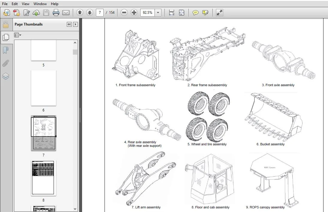
 Dividing Process Overview (Major components alone).........................................................................  7
2. Major Components Table of Dimensions........................................................................................  8
3. Work Space Layout........................................................................................................... 10
4. Schedule Table for Field Assembly........................................................................................... 11
5. Facility, Jigs and Tools.................................................................................................... 12
6. List of Oil, Grease and Paints.............................................................................................. 15
7. Assembly procedure..........................................................................................................  0
	0010 Oil, grease and coolant............................................................................................... 16
	0020 Oil, grease and coolant level......................................................................................... 17
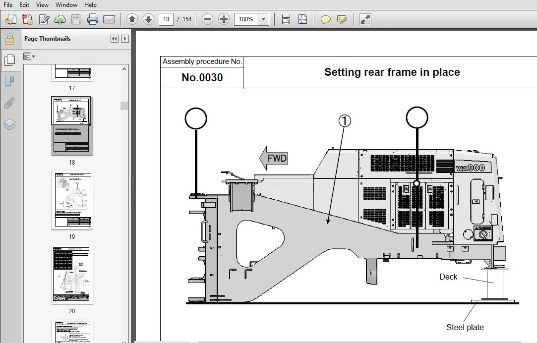
	0030 Setting rear frame in place........................................................................................... 18
	0040 Setting front frame in place.......................................................................................... 19
	0050 Joining front and rear frames......................................................................................... 20
	0060 Front and rear frames joining procedure............................................................................... 21
	0070 Assembling the steering pin........................................................................................... 22
	0080 Assembling the center drive shat (Center support - Transmission)...................................................... 27
	0090 Connection of piping (Part 1)......................................................................................... 28
	0100 Connection of piping (Part 2)......................................................................................... 29
	0101 Connection of piping (Part 2)  (7XC47: Front and rear frame combination load figure).................................. 30
	0105 Connection of piping (Part 2)  (Riotinto specification: If equipped).................................................. 31
	0110 Connecting the auto-greasing pipe..................................................................................... 32
	0120 Setting the axle in place and assembling the support.................................................................. 33
	0130 Setting the bare machine in place..................................................................................... 34
	0140 Assembling the rear axle.............................................................................................. 35
	0150 Rear axle rear side cover assembling procedure........................................................................ 36
	0160 Connecting the rear axle pipe......................................................................................... 37
	0165 Fixing of rear axle piping (Brake cooling specification: If equipped)................................................. 38
	0166 Connection of rear axle piping (Riotinto specification: If equipped).................................................. 39
	0167 Fixing of rear axle piping (Brake cooling specification: If equipped)................................................. 40
	0168 Connection of cooling line piping (Brake cooling specification: If equipped).......................................... 41
	0170 Assembling the rear drive shaft (Transmission - Rear axle)............................................................ 42
	0180 Assembling the front axle............................................................................................. 43
	0182 Fixing of front axle piping (Brake cooling specification: If equipped)................................................ 44
	0185 Connection of front axle piping (Brake cooling specification: If equipped)............................................ 45
	0190 Connecting the front axle pipe........................................................................................ 46
	0195 Connection of front axle piping (Riotinto specification: If equipped)................................................. 47
	0200 Connecting the front drive shat (Front axle . Center support)......................................................... 48
	0205 Connection of front axle brake oil temperature sensor................................................................. 49
	0210 Connecting the axle oil temperature sensor (For VHMS specification only).............................................. 50
	0220 Assembling the tires.................................................................................................. 51
	0230 Assembling the fuel tank.............................................................................................. 52
	0235 Installation of fuel tank (Riotinto specification: If equipped)....................................................... 53
	0240 Fixing the drain pipe................................................................................................. 54
	0245 Fixing of torque converter cooler drain piping (Riotinto specification: If equipped).................................. 55
	0250 Connecting the fuel pipe.............................................................................................. 56
	0255 Fixing of breather hose............................................................................................... 57
	0260 Fixing the engine drain hoses......................................................................................... 58
	0270 Assembling the hydraulic tank ladder.................................................................................. 59
	0280 Assembling the floor and cab assembly................................................................................. 60
	0290 Connecting the air conditioner hose................................................................................... 61
	0300 Connecting the brake line............................................................................................. 62
	0310 Connecting the window washer hose..................................................................................... 63
	0320 Connecting the PPC line hose.......................................................................................... 64
	0330 Connecting the floor wiring harness................................................................................... 65
	0331 Connecting the floor wiring harness (Steering wheel specification: If equipped)....................................... 66
	0333 Connection of floor wiring harness -1 (Riotinto specification: If equipped)........................................... 67
	0334 Connection of floor wiring harness -2 (Riotinto specification: If equipped)........................................... 68
	0335 Connecting the steering line (Steering wheel specification :If equipped).............................................. 69
	0340 Connecting the link for AJSS (For AJSS specification only)............................................................ 70
	0345 Calibration of the AJSS angle and frame offset angle.................................................................. 71
	0350 Assembling the auto-greasing pump and connecting the pipe (WA900-3E0 North American specification).................... 72
	0360 Assembling the floor cover............................................................................................ 73
	0370 Refilling the window washer........................................................................................... 74
	0380 Assembling the battery box............................................................................................ 75
	0390 Connecting and fixing the battery wiring.............................................................................. 76
	0393 Wiring on right side of battery (Riotinto specification: If equipped)................................................. 77
	0394 Wiring on left side of battery -1 (Riotinto specification: If equipped)............................................... 78
	0395 Wiring on left side of battery -2 (Riotinto specification: If equipped)............................................... 79
	0396 Wiring on left side of battery -3 (Riotinto specification: If equipped)............................................... 80
	0397 Connection of ground cable on left side of battery (Riotinto specification: If equipped).............................. 81
	0400 Assembling the battery step........................................................................................... 82
	0403 Installation of oil cooler assembly (Brake cooling specification: If equipped)........................................ 83
	0404 Installation and connection of oil cooler assembly piping (Brake cooling specification: If equipped).................. 84
	0406 Installation of oil cooler assembly piping -1 (Brake cooling specification: If equipped).............................. 85
	0407 Installation of oil cooler assembly piping -2 (Brake cooling specification: If equipped).............................. 86
	0410 Assembling the handrail (On the right hand platform).................................................................. 87
	0411 Installation of handrail (Right platform area) (Brake cooling specification: If equipped)............................. 88
	0420 Assembling the handrail (On the hood top face)........................................................................ 89
	0425 Installation of handrail to step in front of CAB(PDI specification : If equipped)..................................... 90
	0426 Installation of mirror to step in front of CAB (PDI specification : If equipped)...................................... 91
	0427 Installation of handrail to upper surface of HOOD (PDI specification : If equipped)................................... 92
	0428 Installation of switch to upper surface of HOOD (PDI specification : If equipped)..................................... 93
	0430 Assembling the handrail (On the right hand battery box)............................................................... 94
	0440 Assembling the rear access step....................................................................................... 95
	0450 Assembling the left handrail (Part 1)................................................................................. 96
	0460 Assembling the left handrail (Part 2)................................................................................. 97
	0461 Installation of left handrail (Part 2) (Brake cooling specification: If equipped)..................................... 98
	0470 Assembling the rearview mirror........................................................................................ 99
	0471 Installation of rearview mirrors (Brake cooling specification: If equipped)...........................................100
	0480 Assembling the exhaust pipe...........................................................................................101
	0485 Installation of oil cooler guard assembly (Brake cooling specification: If equipped)..................................102
	0486 Installation of fan motor piping cover -1 (Brake cooling specification: If equipped)..................................103
	0487 Installation of fan motor piping cover -2 (Brake cooling specification: If equipped)..................................104
	0490 Applying the counterweight anti-slip..................................................................................105
	0500 Assembling the counterweight (WA900-3E0 standard specification).......................................................106
	0505 Assembling the counterweight (WA900-3E0 High-lift arm specification)..................................................107
	0510 Assembling the counterweight (WA800-3E0 Overseas general, optional specification and North American specification)....108
	0520 Assembling the counterweight (WA800-3E0 Overseas general standard specification)......................................109
	0530 Assembling the front axle lamp and connecting the harness.............................................................110
	0540 Assembling the front lamp assembly....................................................................................111
	0550 Assembling the ROPS canopy assembly...................................................................................112
	0560 Assembling the antenna and work lamp..................................................................................113
	0570 Assembling the VHMS antenna (For VHMS specification only).............................................................114
	0580 Assembling the floor mat..............................................................................................115
	0590 Assembling the front fender...........................................................................................116
	0600 Engine starting procedure.............................................................................................117
	0610 Bleeding the brake air................................................................................................118
	0615 Bleeding air from hydraulic circuit...................................................................................119
	0620 Assembling the lift arm assembly (Part 1).............................................................................120
	0630 Assembling the lift arm assembly (Part 2).............................................................................121
	0640 Connecting the remote grease tube.....................................................................................122
	0650 Assembling the bucket (Part 1)........................................................................................123
	0660 Assembling the bucket (Part 2)........................................................................................124
	0670 Assembling the bucket (Part 3)........................................................................................125
	0680 Assembling the cover (Bottom of the counterweight)....................................................................126
	0681 Assembling the cover (Bottom of the counterweight) (For KAL PDI)......................................................127
	0690 Feeding the grease....................................................................................................128
	0700 Work equipment hydraulic circuit air bleeding procedure...............................................................129
	0710 Adjusting the bucket positioner.......................................................................................130
	0720 Adjusting the new 2 stage (Overseas general standard).................................................................131
	0730 Adjusting the new 2 stage (North American standard specification).....................................................132
	0740 Assembling the lift arm angle sensor..................................................................................133
	0750 Adjusting the active working system and boom kick-out switch
(Overseas general standard and domestic standard)".......134
	0760 Touchup work..........................................................................................................135
	0770 Applying the decal (For the overseas-directed products only)..........................................................136
Appendix: Field assembly inspection report.....................................................................................137
KOMATSU WA800-3EO WA900-3EO WHEEL LOADER FIELD ASSEMBLY INSTRUCTION MANUAL SN 70001, 60001 AND UP – PDF DOWNLOAD:
IMAGES PREVIEW OF THE MANUAL:
PLEASE NOTE:
- This is the SAME MANUAL used by the dealerships to diagnose your vehicle
- No waiting for couriers / posts as this is a PDF manual and you can download it within 2 minutes time once you make the payment.
- Your payment is all safe and the delivery of the manual is INSTANT – You will be taken to the DOWNLOAD PAGE.
- So have no hesitations whatsoever and write to us about any queries you may have : heydownloadss @gmail.com



