Komatsu WD600-6R Wheel Dozer Shop Manual SEN06588-06 – PDF DOWNLOAD
Original price was: $89.95.$36.95Current price is: $36.95.
Komatsu WD600-6R Wheel Dozer Shop Manual SEN06588-06 – PDF DOWNLOAD
SERIAL NUMBERS 60001 and up
Description
Komatsu WD600-6R Wheel Dozer Shop Manual SEN06588-06 – PDF DOWNLOAD
IMAGES PREVIEW OF THE MANUAL:
DESCRIPTION:
Komatsu WD600-6R Wheel Dozer Shop Manual SEN06588-06 – PDF DOWNLOAD
SERIAL NUMBERS 60001 and up
How to read the shop manual:
1. Composition of shop manual
This shop manual contains the necessary technical information for services performed in a workshop.
For ease of understanding, the manual is divided into the following sections.
00. Index and foreword:
This section explains the shop manuals list, table of contents, safety, and basic information.
01. Specification:
This section explains the specifications of the machine.
10. Structure, function and maintenance standard
This section explains the structure, function, and maintenance standard values of each component.
The structure and function sub-section explains the structure and function of each component. It
serves not only to give an understanding of the structure, but also serves as reference material for
troubleshooting. The maintenance standard sub-section explains the criteria and remedies for disassembly
and service.
20. Standard value table
This section explains the standard values for new machine and judgement criteria for testing,
adjusting, and troubleshooting. This standard value table is used to check the standard values in
testing and adjusting and to judge parts in troubleshooting.
30. Testing and adjusting
This section explains measuring instruments and measuring methods for testing and adjusting, and
method of adjusting each part. The standard values and judgement criteria for testing and adjusting
are explained in Testing and adjusting.
40. Troubleshooting
This section explains how to find out failed parts and how to repair them. The troubleshooting is
divided by failure modes. The “S mode” of the troubleshooting related to the engine may be also
explained in the Chassis volume and Engine volume. In this case, see the Chassis volume.
50. Disassembly and assembly
This section explains the special tools and procedures for removing, installing, disassembling, and
assembling each component, as well as precautions for them. In addition, tightening torque and
quantity and weight of coating material, oil, grease, and coolant necessary for the work are also
explained.
90. Diagrams and drawings (chassis volume)/Repair and replacement of parts (engine volume)
q Chassis volume
This section gives hydraulic circuit diagrams and electrical circuit diagrams.
q Engine volume
This section explains the method of reproducing, repairing, and replacing parts.
Questions? Email us: [email protected]
https://vimeo.com/743650172
TABLE OF CONTENTS:
Komatsu WD600-6R Wheel Dozer Shop Manual SEN06588-06 – PDF DOWNLOAD
COVER 1
Notice of revision 3
00 Index and foreword 13
Table of contents 14
Foreword and general information 26
Safety notice 26
How to read the shop manual 31
Explanation of terms for maintenance standard 33
Handling of electric equipment and hydraulic component 35
Handling of connectors newly used for engines 44
How to read electric wire code 47
Precautions when carrying out operation 50
Method of disassembling and connecting push-pull type coupler 53
Standard tightening torque table 56
Conversion table 60
01 Specification 65
Specification and technical data 67
Specification dimension drawing 67
Specifications 68
Weight table 71
Table of fuel, coolant and lubricants 73
10 Structure, function and maintenance standard 75
Engine and cooling system 78
Engine mount and transmission mount 78
Damper 80
Cooling system 82
Cooling fan pump 86
Cooling fan motor 94
Power train 100
Power train 100
Power train system diagram 101
Torque converter and transmission piping diagram 102
Torque converter 104
Modulation clutch 113
Torque converter regulator valve 114
Transmission 116
Transfer 136
Transmission control valve 138
ECMV 140
Main relief valve and torque converter relief valve 147
Lubrication relief valve 149
Torque converter oil cooler 150
Torque converter oil filter 151
Drive shaft 153
Center support 156
Axle 158
Differential 162
Limited slip differential 171
Final drive 176
Steering system 180
Steering piping diagram 180
Steering column 182
Joystick steering lever linkage 183
Joystick EPC valve 184
Lock valve 185
Steering valve 186
Rotary valve 189
Steering control valve 192
Two-way restrictor valve 208
Stop valve 209
Steering pump 210
Steering cylinder 224
Emergency steering piping diagram 225
Diverter valve 226
Emergency steering pump 234
Brake system 236
Brake piping diagram 236
Brake 238
Brake valve 242
Accumulator charge valve 250
EPC relief valve 256
Accumulator (for brake) 258
Slack adjuster 260
Parking brake 264
Parking brake solenoid valve 266
Emergency parking brake release valve 268
Brake cooling pump 269
Undercarriage and frame 270
Axle mount 270
Center hinge pin 275
Hydraulic system 278
Hydraulic piping diagram 278
Work equipment control lever linkage 280
Hydraulic tank 282
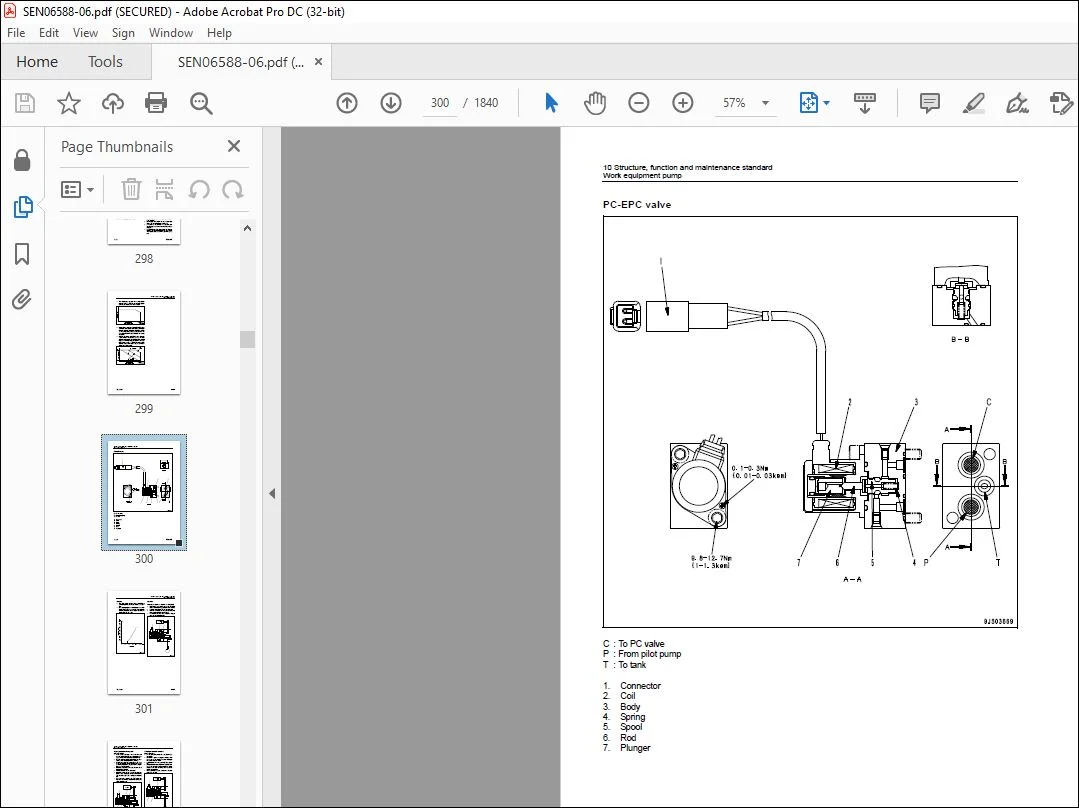
Work equipment pump 284
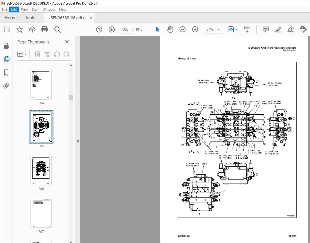
Control valve 304
CLSS 318
Functions and operation by valve 322
Accumulator (for PPC circuit) 332
Triple pump 333
Work equipment 334
Work equipment linkage 334
Cutting edge and end bit 337
Work equipment lubrication 339
Hydraulic cylinder 342
Cab and its attachments 344
ROPS cab 344
Air conditioner 346
Electrical system 350
Machine monitor system 350
Machine monitor 356
Work equipment control system 404
Transmission controller system 430
Electric transmission control 462
Engine starting/stopping circuit 464
Parking brake circuit 467
Sensor 471
VHMS controller related 492
VHMS controller and wireless LAN system 494
Electric lever (Work equipment) 501
20 Standard value table 505
Standard service value table 507
Standard service value table for engine 507
Standard service value table for chassis 508
30 Testing and adjusting 517
Related information on testing and adjusting 520
Tools for testing, adjusting, and troubleshooting 520
Engine and cooling system 527
Measuring engine speed 527
Measuring exhaust gas color 529
Measuring exhaust temperature 530
Adjusting valve clearance 532
Testing compression pressures 534
Measuring blowby pressure 537
Measuring engine oil pressure 538
Measuring intake air (boost) pressure 539
Handling fuel system equipment 540
Releasing residual pressure in fuel system 540
Testing fuel pressures 541
Testing return rate and leakage 542
Bleeding air from fuel circuit 545
Testing leakage in fuel system 547
Handling reduced cylinder mode operation 548
Handling no-injection cranking operation 548
Handling controller voltage circuit 549
Replacing and adjusting alternator and air conditioner compressor belt tension 550
Power train 551
Adjusting modulation clutch speed sensor and speed sensor 551
Measuring directional lever and gear shift lever (Steering wheel specification) 553
Testing and adjusting power train oil pressure 554
Flushing procedure for torque converter and transmission hydraulic circuit 568
Method of moving machine when transmission valve is broken 570
Moving method of machine disabled by short-to-power failure in work equipment potentiometer 572
Steering system 574
Adjusting steering stop valve 574
Measuring operating effort of AJSS lever (AJSS specification) 575
Testing and adjusting AJSS lever angle sensor and frame angle sensor (AJSS specification) 576
Testing and adjusting steering stopper bolt (AJSS specification) 578
Testing and adjusting steering wheel (Steering wheel specification) 580
Testing steering oil pressure 582
Bleeding air from steering cylinder circuit 586
Testing hydraulic drive fan 587
Bleeding air from hydraulic drive fan circuit 590
Brake system 592
Measuring brake pedal 592
Measuring brake performance 593
Testing and adjusting accumulator charge pressure 594
Testing of accumulator nitrogen gas pressure and procedure for charging brake accumulator with nitrogen gas 596
Testing wheel brake oil pressure 604
Measuring wear of wheel brake disc 606
Bleeding air from wheel brake circuit 607
Releasing residual pressure in brake accumulator circuit 608
Testing parking brake performance 609
Measuring parking brake oil pressure 610
Testing wear of parking brake disc 613
Method of releasing parking brake manually 614
Hydraulic system 615
Measuring and adjusting work equipment control lever 615
Measuring work equipment oil pressure 616
Releasing residual pressure in work equipment circuit 621
Bleeding air from work equipment circuit 623
Cab and its attachments 624
Moving machine for removing operator cab 624
Electrical system 626
Preparations for work on troubleshooting of electric system 626
Procedure for testing diodes 630
Machine monitor-based adjustment at replacement, disassembly and assembly, and additional installation for each sensor and controller 631
Special functions of machine monitor (EMMS) 635
VHMS controller initial settingprocedure (ORBCOMM installationspecification) 704
VHMS controller initial settingprocedure (IRIDIUM installationspecification) 726
Precautions for replacing VHMS controller 748
Initialization of VHMS wireless LAN modem and downloading of data 754
Pm-clinic 762
Pm-clinic inspection table 762
40 Troubleshooting 765
Related information on troubleshooting 773
Points to remember when performing troubleshooting 773
How to proceed in troubleshooting 775
Testing before troubleshooting 777
Classification and procedures of troubleshooting 778
Failure codes list 782
Information in troubleshooting table 794
Troubleshooting method for disconnecting wiring harness of pressure sensor system 796
Connection table for connector pin numbers 799
T- branch box and T- branch adapter table 835
Fuse locations 838
Troubleshooting by failure code (Display of code) 841
Failure code [1500L0] TORQFLOW transmission: Double meshing 841
Failure code [15B0NX] Transmission Oil Filter Clogging 842
Failure code [15SAL1] ECMV F clutch: When command current is OFF, fill signal is ON 844
Failure code [15SALH] ECMV F clutch: When command current is ON, fill signal is OFF 846
Failure code [15SBL1] ECMV R clutch: When command current is OFF, fill signal is ON 848
Failure code [15SBLH] ECMV R clutch: When command current is ON, fill signal is OFF 850
Failure code [15SEL1] ECMV (1): When command current is OFF, fill signal is ON 852
Failure code [15SELH] ECMV (1): When command current is ON, fill signal is OFF 854
Failure code [15SFL1] ECMV (2): When command current is OFF, fill signal is ON 856
Failure code [15SFLH] ECMV (2): When command current is ON, fill signal is OFF 858
Failure code [15SGL1] ECMV (3): When command current is OFF, fill signal is ON 860
Failure code [15SGLH] ECMV (3): When command current is ON, fill signal is OFF 862
Failure code [15SHL1] ECMV (4): When command current is OFF, fill signal is ON 864
Failure code [15SHLH] ECMV (4): When command current is ON, fill signal is OFF 866
Failure code [15W0NT] Transmission modulation clutch: Overheating 868
Failure code [2F00MA] Parking brake: Malfunction 869
Failure code [2G42ZG] Front Accumulator Oil Pressure Low 872
Failure code [2G43ZG] Rear Accumulator Oil Pressure Low 874
Failure code [A000N1] (or VHMS_LED display: “n2” → “01”) Engine: Overrun 877
Failure code [AA1ANX] Air Cleaner Clogging 878
Failure code [AB00L6] Alternator: Signal disagrees with run and stop of engine 880
Failure code [AB00MA] Alternator: Malfunction 882
Failure code [B@BAZG] Engine oil pressure: Low error 884
Failure code [B@BAZK] Eng Oil Level Low 885
Failure code [B@BCNS] Engine coolant temperature: Overheating 886
Failure code [B@BCZK] Engine coolant level low 888
Failure code [B@C7NS] Brake oil overheating 890
Failure code [b@CENS] Torque converter oil overheating 891
Failure code [B@CENS] Torque converter oil overheating 892
Failure code [B@GAZK] Low Battery Fluid Level 893
Failure code [B@HANS] Hyd Oil Overheat 894
Failure code [CA111] Abnormality in engine controller 896
Failure code [CA115] Engine Ne or Bkup speed sensor error 899
Failure code [CA122] Charge (boost) pressure sensor high error 900
Failure code [CA123] Charge (boost) pressure sensor low error 902
Failure code [CA131] Throttle sensor high error 904
Failure code [CA132] Throttle sensor low error 907
Failure code [CA135] Engine oil pressure sensor high error 910
Failure code [CA141] Engine oil pressure sensor low error 912
Failure code [CA144] Coolant temperature sensor high error 914
Failure code [CA145] Coolant temperature sensor low error 916
Failure code [CA153] Charge (boost) temperature sensor high error 918
Failure code [CA154] Charge (boost) temperature sensor low error 920
Failure code [CA187] Sensor power supply 2 low error 922
Failure code [CA212] Engine oil temperature sensor high error 924
Failure code [CA213] Engine oil temperature sensor low error 926
Failure code [CA221] Atmospheric pressure sensor high error 928
Failure code [CA222] Atmospheric pressure sensor low error 930
Failure code [CA227] Sensor power supply 2 high error 932
Failure code [CA234] Engine overspeed 933
Failure code [CA238] Ne speed sensor power supply error 934
Failure code [CA263] Fuel temperature sensor high error 936
Failure code [CA265] Fuel temperature sensor low error 938
Failure code [CA271] PCV1 Short circuit 940
Failure code [CA272] PCV1 Disconnection 941
Failure code [CA273] PCV2 Short circuit 942
Failure code [CA274] PCV2 Disconnection 943
Failure code [CA322] Injector #1 open/short error 944
Failure code [CA323] Injector #5 open/short error 946
Failure code [CA324] Injector #3 open/short error 948
Failure code [CA325] Injector #6 open/short error 950
Failure code [CA331] Injector #2 open/short error 952
Failure code [CA332] Injector #4 open/short error 954
Failure code [CA342] Calibration code inconsistency 956
Failure code [CA351] Injectors drive circuit error 957
Failure code [CA352] Sensor power supply 1 low error 958
Failure code [CA386] Sensor power supply 1 high error 960
Failure code [CA431] Idle validation switch error 961
Failure code [CA432] Idle validation action error 964
Failure code [CA441] Battery voltage low error 967
Failure code [CA442] Battery voltage high error 968
Failure code [CA449] Common rail pressure high error 2 969
Failure code [CA451] Common rail pressure sensor high error 970
Failure code [CA452] Common rail pressure sensor low error 972
Failure code [CA553] Common rail pressure high error 1 974
Failure code [CA554] Common rail pressure sensor in range error 975
Failure code [CA559] Supply pump pressure very low error 1 976
Failure code [CA689] Engine Ne speed sensor error 980
Failure code [CA731] Engine Bkup speed sensor phase error 982
Failure code [CA757] All continuous data lost error 983
Failure code [CA778] Engine Bkup speed sensor error 984
Failure code [CA1633] KOMNET datalink timeout error 986
Failure code [CA2185] Throttle sensor supply voltage high error 988
Failure code [CA2186] Throttle sensor power supply low error 990
Failure code [CA2249] Supply pump pressure very low error 2 992
Failure code [CA2555] Intake air heater relay open circuit error 994
Failure code [CA2556] Intake air heater relay short circuit error 996
Failure code [D191KA] AJSS neutral safety relay open circuit 998
Failure code [D191KB] AJSS neutral safety relay short circuit 1000
Failure code [D198KA] Transmission oil pressure bypass solenoid: Disconnection 1002
Failure code [D198KB] Transmission oil pressure bypass solenoid: Short circuit 1003
Failure code [D198KY] Transmission oil pressure bypass solenoid: Short circuit with power supply line 1004
Failure code [D5ZHKA] Terminal C signal open circuit 1006
Failure code [D5ZHKB] Terminal C signal short circuit 1008
Failure code [D5ZHKZ] Terminal C signal open or short circuit 1010
Failure code [D5ZHL6] Terminal C signal disagrees with run and stop of engine 1012
Failure code [DA80L4] Auto-greasing controller disagrees with ON/OFF signal 1014
Failure code [DAF3KK] Machine monitor: Source voltage low (input) 1016
Failure code [DAF5KP] Machine monitor: Output voltage low 1018
Failure code [DAFRKR] CAN communication with machine monitor: Communication error (Abnormality in target component system) 1020
Failure code [DAQ0KK] Transmission controller: Source voltage low 1021
Failure code [DAQ0KT] Transmission controller: Defect in controller 1024
Failure code [DAQ2KK] Transmission controller load power supply line: Source voltage low (Input) 1026
Failure code [DAQ9KQ] Transmission controller model selection: Model selection signal disagreement 1029
Failure code [DAQRKR] CAN communication with transmission controller: Communication error (Abnormality in target component system) 1030
Failure code [DAQRMA] Transmission controller (Option setting): Malfunction 1035
Failure code [DB2RKR] CAN communication from engine controller: Communication error (Abnormality in target component system) 1036
Failure code [DB90KK] Work equipment controller: Source voltage low (input) 1039
Failure code [DB90KT] Work equipment controller: Defect in controller 1042
Failure code [DB92KK] Work equipment controller load power supply line: Source voltage low (input) 1043
Failure code [DB95KX] Work equipment controller power supply output: Out of range 1046
Failure code [DB99KQ] Work equipment controller model selection: Model selection signal disagreement 1048
Failure code [DB9RKR] CAN communication with work equipment controller: Communication error (Abnormality in target component system) 1049
Failure code [DB9RMA] Work equipment controller (Option setting): Malfunction 1050
Failure code [DB9RMC] CAN communication with transmission controller: Malfunction 1051
Failure code [DBB0KK] or change of VHMS_LED display from “n9” to “01” (VHMS controller: Source voltage low (input)) 1052
Failure code [DBB0KQ] or change of VHMS_LED display from “nF” to “11” (VHMS controller: Disagreement of model selection signals) 1054
Failure code [DBB3KK] or change of VHMS_LED display from “n9” to “05” (VHMS controller battery power supply: Source voltage low (input)) 1056
Failure code [DBB5KP] or change of VHMS_LED display from “n9” to “04” (VHMS controller 5 V power supply output: Output voltage low) 1058
Failure code [DBB6KP] or change of VHMS_LED display from “n9” to “02” (VHMS controller 24V power supply output: Output voltage low) 1060
Failure code [DBB7KP] or change of VHMS_LED display from “n9” to “03” (VHMS controller 12V power supply output: Output voltage low) 1062
Failure code [DBBQKR] or change of VHMS_LED display from “n8” to “02” (CAN communication of VHMS controller: Communication error (Abnormality in target component system)) 1064
Failure code [DD15LD] t switch (Panel switch 1): Switch is kept pressed for long time 1066
Failure code [DD16LD] U switch (Panel switch 2): Switch is kept pressed for long time 1068
Failure code [DD17LD] < switch (Panel switch 3): Switch is kept pressed for long time 1070
Failure code [DD18LD] > switch (Panel switch 4): Switch is kept pressed for long time 1072
Failure code [DDA7L4] RPM set ON/OFF switch: ON-OFF signals disagree 1074
Failure code [DDA8KB] RPM set idle-up/down selector switch (idle-up): Short circuit 1076
Failure code [DDA9KB] RPM set idle-up/down selector switch (idle-down): Short circuit 1079
Failure code [DDB6L4] Parking brake switch (Neutralizer): ON/OFF signals disagree 1082
Failure code [DDD1LD] Pitch operation switch: Switch is kept pressed for long time 1086
Failure code [DDDBKA] Traction adjustment dial: Disconnection 1088
Failure code [DDDBKB] Traction adjustment dial: Short circuit 1090
Failure code [DDE5MA] Emergency steering drive switch: Malfunction 1092
Failure code [DDK4KA] AJSS FNR switch: Disconnection 1094
Failure code [DDK4KB] AJSS FNR switch: Short circuit 1096
Failure code [DDK5L4] AJSS shift-up/down switch: ON/OFF signals disagree 1098
Failure code [DDK6KA] FNR lever switch: Disconnection 1101
Failure code [DDK6KB] FNR lever switch: Short circuit 1104
Failure code [DDP5KA] Lock detection pressure switch of steering lock lever: Disconnection 1106
Failure code [DDT0L4] Shift mode selector switch: ON/OFF signals disagree 1108
Failure code [DDW9LD] Kick-down switch: Switch is kept pressed for long time 1110
Failure code [DDWLLD] Hold switch: Switch is kept pressed for long time 1112
Failure code [DF10KA] Transmission shift lever switch: Disconnection 1114
Failure code [DF10KB] Transmission shift lever switch: Short circuit 1118
Failure code [DGE5KX] (or VHMS_LED display: “n4” → “01”) Atmospheric temperature sensor: Out of input signal range 1120
Failure code [DGF1KA] Transmission oil temperature sensor: Disconnection 1122
Failure code [DGF1KB] Transmission oil temperature sensor: Short circuit 1124
Failure code [DGH2KX] Hydraulic oil temperature sensor: Out of input signal range 1126
Failure code [DGR2KA] Rear brake oil temperature sensor: Disconnection 1128
Failure code [DGR2KX] Rear brake oil temperature sensor: Out of input signal range 1130
Failure code [DGT1KA] Torque converter oil temperature sensor: Disconnection 1132
Failure code [DGT1KB] Torque converter oil temperature sensor: Short circuit 1134
Failure code [DGT1KX] Torque converter oil temperature sensor: Out of input signal range) 1136
Failure code [DGT4KA] (or VHMS_LED display: “n3” → “12”) Exhaust gas temperature sensor (F): Disconnection 1138
Failure code [DGT4KB] (or VHMS_LED display: “n3” → “11”) Exhaust gas temperature sensor (F): Short circuit 1141
Failure code [DGT5KA] (or VHMS_LED display: “n3” → “22”) Exhaust gas temperature sensor (R): Disconnection 1144
Failure code [DGT5KB] (or VHMS_LED display: “n3” → “21”) Exhaust gas temperature sensor (R): Short circuit 1147
Failure code [DH21KA] Work equipment pump oil pressure sensor: Disconnection 1150
Failure code [DH21KB] Work equipment pump oil pressure sensor: Short circuit 1152
Failure code [DHE5KB] (or VHMS_LED display: “n3” → “32”) Blow-by pressure sensor: Short circuit 1154
Failure code [DHE5KY] (or VHMS_LED display: “n3” → “31”) Blow-by pressure sensor: Short circuit with power supply line 1156
Failure code [DHT2L6] Transmission filter clogging sensor: Signal disagrees with operating state of engine 1158
Failure code [DHT8KX] (or VHMS_LED display: “n5” → “33”) Steering oil pressure sensor: Out of input signal range 1160
Failure code [DHTBKA] Modulation clutch oil pressure sensor: Disconnection 1164
Failure code [DHTBKB] Modulation clutch oil pressure sensor: Short circuit 1166
Failure code [DHU2KX] (or VHMS_LED display: “n7” → “11”) Front brake oil pressure sensor (F): Out of input signal range 1168
Failure code [DHU3KX] (or VHMS_LED display: “n7” → “12”) Rear brake oil pressure sensor (R): Out of input signal range 1170
Failure code [DK30KA] AJSS lever angle sensor: Disconnection 1172
Failure code [DK30KY] AJSS lever angle sensor: Short circuit with power supply line 1174
Failure code [DK59KA] Lift EPC lever potentiometer (Main): Disconnection 1176
Failure code [DK59KY] Lift EPC lever potentiometer (Main): Short circuit with power supply line 1180
Failure code [DK59L8] Lift EPC lever potentiometer (Main): Analog signals disagree 1182
Failure code [DK5AKA] Lift EPC lever potentiometer (Sub): Disconnection 1185
Failure code [DK5AKY] Lift EPC lever potentiometer (Sub): Short circuit with power supply line 1188
Failure code [DK5BKA] Tilt & pitch EPC lever potentiometer (Main): Disconnection 1190
Failure code [DK5BKY] Tilt & pitch EPC lever potentiometer (Main): Short circuit with power supply line 1194
Failure code [DK5BL8] Tilt & pitch EPC lever potentiometer (Main): Analog signals disagree 1196
Failure code [DK5CKA] Tilt & pitch EPC lever potentiometer (Sub): Disconnection 1199
Failure code [DK5CKY] Tilt & pitch EPC lever potentiometer (Sub): Short circuit with power supply line 1202
Failure code [DKD0KA] Frame angle sensor: Disconnection 1204
Failure code [DKD0KY] Frame angle sensor: Short circuit with power supply line 1206
Failure code [DKD0KZ] AJSS lever and frame angle sensor: Disconnection or short circuit 1208
Failure code [DLFAKA] Modulation clutch output shaft speed sensor: Disconnection 1212
Failure code [DLFALC] Modulation clutch output shaft speed sensor: Speed signals disagree 1214
Failure code [DLT3KA] Transmission output shaft speed sensor (2): Disconnection 1216
Failure code [DLT3LC] Transmission output shaft speed sensor (2): Speed signals disagree 1218
Failure code [DLT4KB] Transmission output shaft speed sensor (1): Short circuit 1220
Failure code [DLT4KX] Transmission output shaft speed sensor (1): Out of input signal range 1222
Failure code [DV00KB] Alarm buzzer: Short circuit 1224
Failure code [DW4PKA] Blade raise EPC solenoid: Disconnection 1226
Failure code [DW4PKB] Blade raise EPC solenoid: Short circuit 1228
Failure code [DW4PKY] Blade raise EPC solenoid: Short circuit with power supply line 1229
Failure code [DW4QKA] Blade lower EPC solenoid: Disconnection 1230
Failure code [DW4QKB] Blade lower EPC solenoid: Short circuit 1231
Failure code [DW4QKY] Blade lower EPC solenoid: Short circuit with power supply line 1232
Failure code [DW4RKA] Tilt & pitch EPC solenoid: Disconnection 1233
Failure code [DW4RKB] Tilt & pitch EPC solenoid: Short circuit 1234
Failure code [DW4RKY] Tilt & pitch EPC solenoid: Short circuit with power supply line 1235
Failure code [DW4SKA] Tilt & pitch EPC solenoid: Disconnection 1236
Failure code [DW4SKB] Tilt & pitch EPC solenoid: Short circuit 1237
Failure code [DW4SKY] Tilt & pitch EPC solenoid: Short circuit with power supply line 1238
Failure code [DW7BKA] Fan reverse solenoid: Disconnection 1240
Failure code [DW7BKB] Fan reverse solenoid: Short circuit 1242
Failure code [DW7BKY] Fan reverse solenoid: Short circuit with power supply line 1244
Failure code [DWM1KA] Work equipment neutral lock solenoid: Disconnection 1246
Failure code [DWM1KB] Work equipment neutral lock solenoid: Short circuit 1248
Failure code [DWM1KY] Work equipment neutral lock solenoid: Short circuit with power supply line 1250
Failure code [DWN7KA] Blade float magnet detent solenoid: Disconnection 1252
Failure code [DWN7KB] Blade float magnet detent solenoid: Short circuit 1254
Failure code [DWN7KY] Blade float magnet detent solenoid: Short circuit with power supply line 1256
Failure code [DWNFKA] Modulation clutch cut-off release solenoid: Disconnection 1258
Failure code [DWNFKB] Modulation clutch cut-off release solenoid: Short circuit 1260
Failure code [DWNFKY] Modulation clutch cut-off release solenoid: Short circuit with power source line 1262
Failure code [DX16KA] Fan pump EPC solenoid: Disconnection 1264
Failure code [DX16KB] Fan pump EPC solenoid: Short circuit 1265
Failure code [DX16KY] Fan pump EPC solenoid: Short circuit with power supply line 1266
Failure code [DXA1KA] Pump PC-EPC solenoid: Disconnection 1267
Failure code [DXA1KB] Pump PC-EPC solenoid: Short circuit 1268
Failure code [DXF0KA] AJSS EPC solenoid: Disconnection 1269
Failure code [DXF0KB] AJSS EPC solenoid: Short circuit 1270
Failure code [DXH1KA] Lockup ECMV solenoid: Disconnection 1272
Failure code [DXH1KB] Lockup ECMV solenoid: Short circuit 1274
Failure code [DXH1KY] Lockup ECMV solenoid: Short circuit with power supply line 1276
Failure code [DXH4KA] 1st clutch ECMV solenoid: Disconnection 1278
Failure code [DXH4KB] 1st clutch ECMV solenoid: Short circuit 1280
Failure code [DXH4KY] 1st clutch ECMV solenoid: Short circuit with power supply line 1282
Failure code [DXH5KA] 2nd clutch ECMV solenoid: Disconnection 1284
Failure code [DXH5KB] 2nd clutch ECMV solenoid: Short circuit 1286
Failure code [DXH5KY] 2nd clutch ECMV solenoid: Short circuit with power supply line 1288
Failure code [DXH6KA] 3rd clutch ECMV solenoid: Disconnection 1290
Failure code [DXH6KB] 3rd clutch ECMV solenoid: Short circuit 1292
Failure code [DXH6KY] 3rd clutch ECMV solenoid: Short circuit with power supply line 1294
Failure code [DXH7KA] R clutch ECMV solenoid: Disconnection 1296
Failure code [DXH7KB] R clutch ECMV solenoid: Short circuit 1298
Failure code [DXH7KY] R clutch ECMV solenoid: Short circuit with power supply line 1300
Failure code [DXH8KA] F clutch ECMV solenoid: Disconnection 1302
Failure code [DXH8KB] F clutch ECMV solenoid: Short circuit 1304
Failure code [DXH8KY] F clutch ECMV solenoid: Short circuit with power supply line 1306
Failure code [DXHHKA] 4th clutch ECMV solenoid: Disconnection 1308
Failure code [DXHHKB] 4th clutch ECMV solenoid: Short circuit 1310
Failure code [DXHHKY] 4th clutch ECMV solenoid: Short circuit with power supply line 1312
Failure code [DXHJKA] RH pitch REAR EPC solenoid: Disconnection 1314
Failure code [DXHJKB] RH pitch REAR EPC solenoid: Short circuit 1315
Failure code [DXHJKY] RH pitch REAR EPC solenoid: Short circuit with power supply line 1316
Failure code [DXHKKA] RH pitch FORWARD EPC solenoid: Disconnection 1317
Failure code [DXHKKB] RH pitch FORWARD EPC solenoid: Short circuit 1318
Failure code [DXHKKY] RH pitch FORWARD EPC solenoid: Short circuit with power supply line 1319
Failure code [DXHPKA] Modulation clutch solenoid: Disconnection 1320
Failure code [DXHPKB] Modulation clutch solenoid: Short circuit 1322
Failure code [DXHPKY] Modulation clutch solenoid: Short circuit with power source line 1324
Failure code [DXHPMA] Modulation clutch solenoid: Malfunction 1326
Failure code [F@BBZL] (or VHMS_LED display: “n3” → “38”) Blow-by pressure: High error 1328
Failure code [F@BYNR] (or VHMS_LED display: “n3” → “62”) Exhaust gas temperature (F): Abnormal heat 1330
Failure code [F@BYNS] (or VHMS_LED display: “n3” → “61”) Exhaust gas temperature (F): Overheat 1332
Failure code [F@BZNR] (or VHMS_LED display: “n3” → “72”) Exhaust gas temperature (R): abnormal heat 1334
Failure code [F@BZNS] (or VHMS_LED display “n3” → “71”) Exhaust gas temperature (R): Overheat 1336
Troubleshooting of electrical system (E-mode) 1338
E-1 Engine does not start 1338
E-2 Wiper does not operate 1348
E-3 Windshield washer does not operate 1356
E-4 Headlamp, clearance lamp, tail lamp, and license lamp do not light up or go off 1362
E-5 Working lamp does not light up or go off 1378
E-6 Step lamp does not light up or go off 1386
E-7 Turn signal lamp and hazard lamp do not light up or go off 1388
E-8 Brake lamp does not light or it keeps lighting up 1398
E-9 Backup lamp does not light or it keeps lighting up 1402
E-10 Backup buzzer does not sound or it keeps sounding 1406
E-11 Horn does not sound or it keeps sounding 1410
E-12 Alarm buzzer does not sound or it keeps sounding 1414
E-13 Air conditioner does not operate or stop 1416
E-14 Electric priming pump does not operate or does not stop automatically 1418
E-15 When starting switch is turned to ON position, machine monitor displays nothing 1420
Troubleshooting of hydraulic and mechanical system (H-mode) 1424
Method of using troubleshooting chart 1424
Table of failure modes and causes 1426
H-1 Machine does not start 1430
H-2 Torque converter lockup is not switched (engine stalls) 1432
H-3 Torque converter lockup is not turned on 1433
H-4 Travel speed is slow, thrusting force is weak, uphill traveling power is weak, and gear is not shifted 1434
H-5 Shocks are large at the times of starting and shifting gear 1436
H-6 Time lag is large at the times of starting and shifting gear 1438
H-7 Torque converter oil temperature is high 1440
H-8 Steering does not turn [machine with steering wheel] 1441
H-9 Steering does not turn [machine with AJSS] 1442
H-10 Turning, response of steering is poor [machine with steering wheel] 1443
H-11 Turning, response of AJSS is poor [machine with AJSS] 1444
H-12 Steering is heavy [machine with steering wheel] 1445
H-13 When machine turns, it shakes or makes large shocks [machine with steering wheel] 1446
H-14 When machine turns, it shakes or makes large shocks [machine with AJSS] 1447
H-15 Wheel brake does not work or does not work well 1448
H-16 Wheel brake is not released or it drags 1449
H-17 Parking brake does not work or does not work well 1450
H-18 Parking brake is not released or it drags (including emergency release system) 1451
H-19 Blade does not rise 1452
H-20 Blade speed is low or rising force of lift is insufficient 1453
H-21 When rising, blade comes to move slowly at specific height 1454
H-22 Lift cylinder cannot hold down blade (Blade floats) 1454
H-23 Hydraulic drifts of blade occur often 1454
H-24 Blade wobbles during operation 1454
H-25 Blade does not tilt and pitch 1455
H-26 Blade speed is low or tilt and pitch force is insufficient 1456
H-27 Blade comes to operate slowly in the midst of tilt and pitch 1457
H-28 Tilt & pitch cylinder cannot hold down blade 1457
H-29 Hydraulic drifts of blade occur often 1457
H-30 Blade wobbles during travel when loaded (Work equipment valve is set to “HOLD”) 1457
H-31 During operation of machine, engine speed lowers remarkably or engine stalls 1458
H-32 Large shocks are made when work equipment starts and stops 1458
H-33 When work equipment circuit is relieved singly, other work equipment moves 1458
H-34 Fan speed is abnormal (Fan sound and vibration are abnormally large or engine overheats) 1459
Troubleshooting of engine (S-mode) 1461
Method of using troubleshooting chart 1461
S-1 Engine does not start easily 1464
S-2 Engine does not start 1465
S-3 Engine does not pick up smoothly 1468
S-4 Engine stops during operation 1469
S-5 Engine does not rotate smoothly (Hunting occurs) 1470
S-6 Engine lacks output (or lacks power) 1471
S-7 Exhaust smoke is black (Incomplete combustion) 1472
S-8 Oil is consumed much (or exhaust gas color is blue) 1473
S-9 Engine oil becomes contaminated quickly 1474
S-10 Fuel consumption is excessive 1475
S-11 Coolant contains oil (blows back or reduces) 1476
S-12 Oil pressure drops 1477
S-13 Oil level rises (Water, fuel in oil) 1478
S-14 Coolant temperature rises too high (Overheating) 1479
S-15 Abnormal noise is made 1480
S-16 Vibration is excessive 1481
S-17 Air cannot be bled from fuel circuit 1482
50 Disassembly and assembly 1485
General information on disassembly and assembly 1488
How to read this manual 1488
Coating materials list 1490
Special tools list 1493
Sketches of special tools 1497
Engine and cooling system 1505
Removal and installation of engine assembly 1505
Removal and installation of radiator assembly 1508
Removal and installation of air aftercooler 1513
Removal and installation of cooling fan and fan motor assembly 1514
Removal and installation of damper assembly 1516
Disassembly and assembly of damper assembly 1518
Removal and installation of fuel tank assembly 1522
Removal and installation of engine hood assembly 1524
Removal and installation of bulkhead assembly 1526
Removal and installation of fuel supply pump assembly 1530
Removal and installation of cylinder head assembly 1536
Removal and installation of fuel injector assembly 1551
Removal and installation of engine front seal 1555
Removal and installation of engine rear seal 1558
Power train 1562
Removal and installation of parking brake assembly 1562
Removal and installation of torque converter and transmission assembly 1564
Disassembly and assembly of torque converter assembly 1569
Disassembly and assembly of transmission assembly 1596
Disassembly and assembly of transfer assembly 1623
Disassembly and assembly of parking brake assembly 1640
Removal and installation of front axle assembly 1647
Removal and installation of rear axle assembly 1649
Removal and installation of center support assembly 1651
Disassembly and assembly of center support assembly 1653
Disassembly and assembly of differential assembly 1657
Removal and installation of final drive carrier assembly 1671
Disassembly and assembly of final drive carrier assembly 1673
Removal and installation of front final drive brake assembly 1674
Disassembly and assembly of final drive assembly 1676
Brake system 1679
Disassembly and assembly of brake assembly 1679
Removal and installation of brake valve assembly 1687
Disassembly and assembly of accumulator and charge valve assembly 1688
Disassembly and assembly of slack adjustor assembly 1691
Undercarriage and frame 1693
Removal and installation of center hinge pin 1693
Removal and installation of counterweight assembly 1700
Hydraulic system 1701
Removal and installation of hydraulic tank assembly 1701
Removal and installation of hydraulic pump assembly 1703
Removal and installation of control valve assembly 1707
Disassembly and assembly of control valve assembly 1709
Removal and installation of steering valve assembly 1714
Disassembly and assembly of hydraulic cylinder assembly 1715
Work equipment 1720
Removal and installation of work equipment assembly 1720
Cab and its attachments 1724
Removal and installation of operator’s cab assembly 1724
Removal and installation of operator’s cab glass (stuck glass) 1728
Removal and installation of floor frame assembly 1736
Disassembly and assembly of operator’s seat assembly 1739
Removal and installation of air conditioner unit assembly 1772
Removal and installation of AJSSlever switch assembly 1775
Electrical system 1781
Removal and installation of engine controller assembly 1781
Removal and installation of transmission controller assembly 1783
Removal and installation of loader controller assembly 1783
Removal and installation of VHMS controller assembly 1784
Removal and installation of machine monitor assembly 1785
90 Diagrams and drawings 1789
Hydraulic diagrams and drawings 1791
Symbols used in hydraulic circuit diagrams 1791
Power train hydraulic circuit diagram 1793
Brake hydraulic circuit diagram 1794
Work equipment hydraulic circuit diagram 1797
Electrical diagrams and drawings 1801
Symbols used in electric circuit diagrams 1801
Air conditioner electrical circuit diagram 1805
Electrical circuit diagram 1807
KOMTRAX electrical circuit diagram 1827
Connector list and layout 1829
Index 1831
PLEASE NOTE:
- This is the same manual used by the DEALERSHIPS to SERVICE your vehicle.
- The manual can be all yours – Once payment is complete, you will be taken to the download page from where you can download the manual. All in 2-5 minutes time!!
- Need any other service / repair / parts manual, please feel free to contact us at heydownloadss @gmail.com . We may surprise you with a nice offer
S.V


