
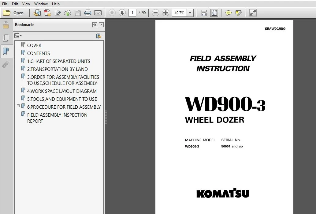
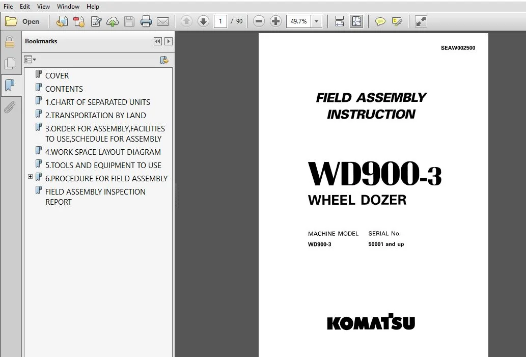
KOMATSU WD900-3 WHEEL DOZER FIELD ASSEMBLY INSTRUCTION MANUAL (SN:50001 & UP) KOMATSU WD900-3 – PDF DOWNLOAD
Original price was: $91.95.$25.95Current price is: $25.95.
- KOMATSU WD900-3 WHEEL DOZER FIELD ASSEMBLY INSTRUCTION MANUAL
- SERIAL NUMBER:50001 & UP
- PUBLICATION NUMBER:SEAW002500
Description
KOMATSU WD900-3 WHEEL DOZER FIELD ASSEMBLY INSTRUCTION MANUAL (SN:50001 & UP) KOMATSU WD900-3
KOMATSU WD900-3 WHEEL DOZER FIELD ASSEMBLY INSTRUCTION MANUAL (SN:50001 & UP) KOMATSU WD900-3 – PDF DOWNLOAD:
IMAGE PREVIEW:
SAMPLE PAGE FROM THE MANUAL:
KOMATSU WD900-3 WHEEL DOZER FIELD ASSEMBLY INSTRUCTION MANUAL (SN:50001 & UP) KOMATSU WD900-3
1. Check all oil and water levels, and add if necessary.
Cooling water level
Engine oil pan oil level
Hydraulic tank oil level
Fuel level
* For details of the‘gauge positions and oil and water levels, see the Operation & Maintenance Manual.
2. Bleed the air from the piston pump For details, see Procedure for Assembly Process N0. M7.
3. Start the engine.
1) For details of starting the engine, see the Operation 8: Maintenance Manual.
* Check the method for stopping the engine.
2) Run the engine for 10 minutes at low idling.
* When doing this, do not move the control levers. it If there is any abnormality, such as oil leakage or abnormal noise, stop the engine immediately.
* For the procedure when starting machines that have been kept in long-term storage of six months or more, see page 80.
4. Check after stopping the engine.
* Check for any oil leakage.
5. Bleed the air from the work equipment hydraulic circuit.
For details, see Procedure for Assembly Process No. M-8.
TABLE OF CONTENTS:
KOMATSU WD900-3 WHEEL DOZER FIELD ASSEMBLY INSTRUCTION MANUAL (SN:50001 & UP) KOMATSU WD900-3
COVER........................................................................... 1
CONTENTS........................................................................ 2
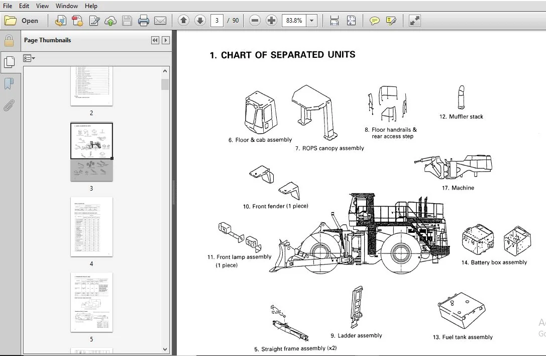
1.CHART OF SEPARATED UNITS...................................................... 3
2.TRANSPORTATION BY LAND........................................................ 5
3.ORDER FOR ASSEMBLY,FACILITIES TO USE,SCHEDULE FOR ASSEMBLY.................... 6
4.WORK SPACE LAYOUT DIAGRAM..................................................... 7
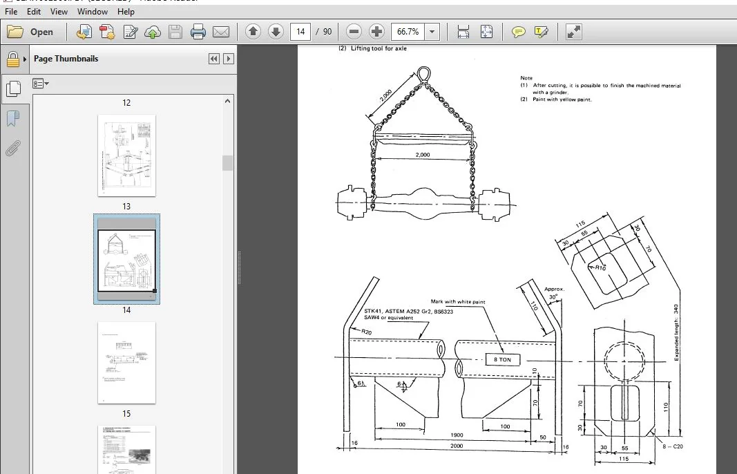
5.TOOLS AND EQUIPMENT TO USE.................................................... 8
6.PROCEDURE FOR FIELD ASSEMBLY..................................................16
	ASSEMBLY PROCESS NO.........................................................16
		A-1 SETTING BARE MACHINE ON SUPPORTS....................................16
		A-2 ASSEMBLY OF REAR AXLE...............................................18
		A-3 ASSEMBLY OF FRONT AND REAR DRIVE SHAFT..............................22
		A-4 ASSEMBLY OF FRONT AXLE..............................................24
		A-5 ASSEMBLY OF FUEL TANK...............................................28
		A-6 ASSEMBLY OF LADDER..................................................34
		A-7 ASSEMBLY OF FLOOR & CAB ASSEMBLY....................................35
		A-8 ASSEMBLY OF HANDRAIL................................................46
		A-9 ASSEMBLY OF TIRE & WHEEL ASSEMBLY...................................47
		A-10 ASSEMBLY OF BATTERY BOX ASSEMBLY...................................49
		A-10A ASSEMBLY OF COUNTERWEIGHT ASSEMBLY................................54
		A-11 ASSEMBLY OF MUFFLER PIPE...........................................55
		A-11A ASSEMBLY OF HANDRAILS & REAR ACCESS STEP..........................56
		A-12 ASSEMBLY OF ADDITIONAL OIL COOLER..................................60
		A-13 ASSEMBLY OF FRONT FENDER...........................................65
		A-14 ASSEMBLY OF FRONT LAMP ASSEMBLY....................................66
		A-15 ASSEMBLY OF ROPS CANOPY ASSEMBLY...................................67
		A-16 ASSEMBLY OF WORK EQUIPMENT.........................................70
		A-17 ASSEMBLY OF FLOOR MAT..............................................76
		M-1 BLEEDING AIR FROM BRAKE LINE........................................77
		M-2 GREASING WORK EQUIPMENT AND CHASSIS.................................78
		M-5 INSPECTION OF ALL PARTS.............................................79
		M-6 PROCEDURE FOR STARTING ENGINE.......................................80
		M-7 PROCEDURE FOR BLEEDING AIR FROM PISTON PUMP.........................82
		M-8 PROCEDURE FOR BLEEDING AIR FROM WORK EQUIPMENT HYDRAULIC CIRCUIT....83
FIELD ASSEMBLY INSPECTION REPORT................................................84
PLEASE NOTE:
⦁ This is not a physical manual but a digital manual – meaning no physical copy will be couriered to you. The manual can be yours in the next 2 mins as once you make the payment, you will be directed to the download page IMMEDIATELY.
⦁ This is the same manual used by the dealers inorder to diagnose your vehicle of its faults.
⦁ Require some other service manual or have any queries: please WRITE to us at [email protected]



