Komatsu WF650T-3 Trash Compactor Shop Manual SEBM027401 – PDF DOWNLOAD
Original price was: $86.95.$36.95Current price is: $36.95.
Komatsu WF650T-3 Trash Compactor Shop Manual SEBM027401 – PDF DOWNLOAD
Description
Komatsu WF650T-3 Trash Compactor Shop Manual SEBM027401 – PDF DOWNLOAD
IMAGES PREVIEW OF THE MANUAL:
Need help? Contact: [email protected]
TABLE OF CONTENTS:
Komatsu WF650T-3 Trash Compactor Shop Manual SEBM027401 – PDF DOWNLOAD
COVER 1
CONTENTS 2
01 GENERAL 27
GENERAL ASSEMBLY DRAWING 28
SPECIFICATIONS 29
WEIGHT TABLE 32
LIST OF LUBRICANT AND WATER 33
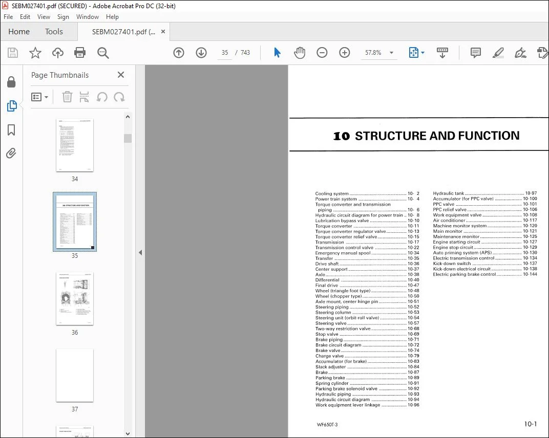
10 STRUCTURE AND FUNCTION 35
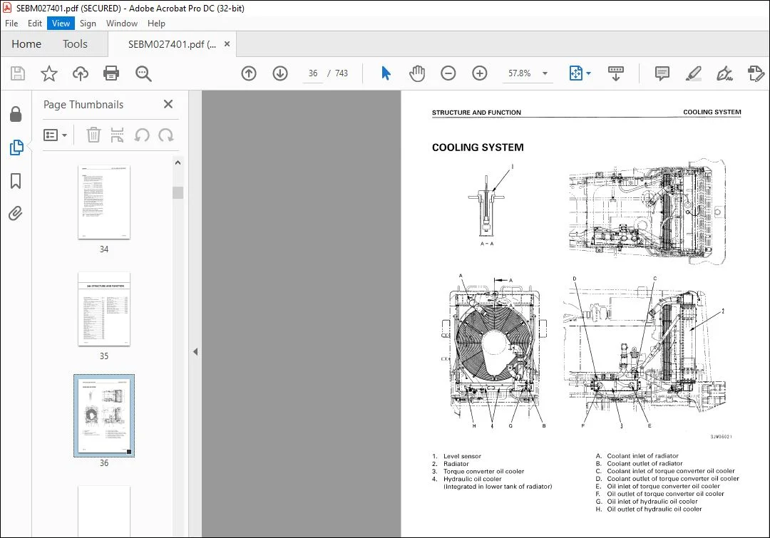
COOLING SYSTEM 36
POWER TRAIN SYSTEM 38
TORQUE CONVERTER AND TRANSMISSION PIPING 40
HYDRAULIC CIRCUIT DIAGRAM FOR POWER TRAIN 42
UBRICATION BYPASS VALVE 44
TORQUE CONVERTER 45
TORQUE CONVERTER REGULATOR VALVE 47
TORQUE CONVERTER RELIEF VALVE 49
TRANSMISSION 51
ANSMISSION CONTROL VALVE 56
ERGENCY MANUAL SPOOL 68
TRANSFER 69
DRIVE SHAFT 70
CENTER SUPPORT 71
AXLE 72
DIFFERENTIAL 74
FINAL DRIVE 81
WHEEL (TRIANGLE FOOT TYPE) 82
WHEEL (CHPPER TYPE) 84
AXLE MOUNT, CENTER HINGE PIN 85
STEERING PIPING 86
STEERING COLUMN 89
STEERING UNIT (ORBIT-ROLL VALVE) 90
STEERING VALVE 93
TWO-WAY RESTRICTION VALVE 104
STOP VALVE 105
BRAKE PIPING 107
BRAKE CIRCUIT DIAGRAM 108
BRAKE VALVE 110
CHARGE VALVE 115
ACCUMULATOR (FOR BRAKE) 119
SLACK ADJUSTER 120
BRAKE 123
PARKING BRAKE 125
SPRING CYLINDER 127
PARKING BRAKE SOLENOID VALVE 128
HYDRAULIC PIPING 129
HYDRAULIC CIRCUIT DIAGRAM 130
WORK EQUIPMENT LEVER LINKAGE 134
HYDRAULIC TANK 135
ACCUMULATOR (FOR PPC VALVE) 138
PPC VALVE 139
PPC RELIEF VALVE 144
WORK EQUIPMENT VALVE 146
AIR CONDITIONER 155
MACHINE MONITOR SYSTEM 158
MAIN MONITOR 159
MAINTENANCE MONITOR 163
ENGINE STARTING CIRCUIT 165
ENGINE STOP CIRCUIT 167
AUTO PRIMING SYSTEM (APS) 168
ELECTRIC TRANSMISSION CONTROL 172
KICK-DOWN SWITCH 175
KICK-DOWN ELECTRICAL CIRCUIT 176
ELECTRIC PARKING BRAKE CONTROL 182
20 TESTING AND ADJUSTING 191
STANDARD VALUE TABLE 191
STANDARD VALUE TABLE FOR ENGINE 192
STANDARD VALUE TABLE FOR CHASSIS 193
STANDARD VALUE TABLE FOR ELECTRICAL PARTS 198
TESTING AND ADJUSTING 205
TABLE OF TOOLS FOR TESTING, ADJUSTING, AND TROUBLESHOOTING 206
MEASURING ENGINE SPEED 207
MEASURING EXHAUST GAS COLOR 209
ADJUSTING VALVE CLEARANCE 210
MEASURING COMPRESSION PRESSURE 211
MEASURING BLOW-BY BRESSURE 212
MEASURING ENGINE OIL PRESSURE 213
TESTING AND ADJUSTING FUEL INJECTION TIMING 214
TESTING AND ADJUSTING ALTERNATOR BELT TENSION 216
TESTING AND ADJUSTING BELT TENSION FOR AIR CONDITIONER COMPRESSOR 216
REPLACING FAN BELT ADJUSTING AUTO-TENSIONER 217
MEASURING EXHAUST TEMPERATURE 218
MEASURING AIR SUPPLY PRESSURE (BOOST PRESSURE) 219
ADJUSTING SPEED SENSOR 220
ADJUSTING FUEL CONTROL CABLE 221
METHOD FOR ADJUSTING ENGINE STOP MOTOR CABLE 222
TESTING AND ADJUSTING TORQUE CONVERTER, TRANSMISSION OIL PRESSURE 224
PROCEDURE FOR FLUSHING TORQUE CONVERTER, TRANSMISSION HYDRAULIC CIRCUIT 228
PROCEDURE FOR MOVING MACHINE WHEN TRANSMISSION VALVE FAILS 229
TESTING AND ADJUSTING STEERING OIL PRESSURE 231
TESTING AND ADJUSTING STEERING STOP VALVE 233
TESTING BRAKE OIL PRESSURE 234
MEASURING WEAR OF BRAKE DISC 235
MEASURING BRAKE PERFORMANCE 236
TESTING AND ADJUSTING PARKING BRAKE 237
TESTING AND ADJUSTING ACCUMULATOR CHARGE CUT-IN AND CUT-OUT PRESSURE 239
TESTING AND ADJUSTING PPC OIL PRESSURE 240
TESTING AND ADJUSTING WORK EQUIPMENT HYDRAULIC PRESSURE 242
AJUSTING WORK EQUIPMENT LEVER LINKAGE 243
ADJUSTING MAIN MONITOR 245
BLEEDING AIR 246
RELEASING REMAINING PRESSURE IN HYDRAULIC CIRCUIT 247
TROUBLESHOOTING 249
POINTS TO REMEMBER WHEN TROUBLESHOOTING 250
SEQUENCE OF EVENTS IN TROUBLESHOOTING 251
POINTS TO REMEMBER WHEN CARRYING OUT MAINTENANCE 252
CHECKS BEFORE TROUBLESHOOTING 260
CONNECTOR TYPES AND MOUNTING LOCATION 262
METHOD OF USING TROUBLESHOOTING CHARTS 288
METHOD OF USING MATRIX TROUBLESHOOTHING TABLES 290
TROUBLESHOOTING OF MAIN MONITOR SYSTEM (M MODE) 293
ELECTRICAL CIRCUIT DIAGRAM FOR MAIN MONITOR 296
ELECTRICAL CIRCUIT DIAGRAM FOR LAMP AND HORN 298
M- 1 Main monitor does not work 299
M- 2 When starting switch is turned ON and engine is started immediately, all lamps stay lighted up 300
M- 3 Speedometer display does not work properly 301
M- 4 Abnormality in shift in dicator 302
a) Displays N even when directional lever is at F 302
b) Displays N even when directional lever is at R 302
c) Does not display N even when directional lever is at N 302
d) Does not display 1st even when speed control lever is at 1st 303
e) Does not display 2nd even when speed control lever is at 2nd 303
f) Does not display 3rd even when speed control lever is at 3rd 303
g) Does not display 4th even when speed control lever is at 4th 303
M- 5 High beam display does not light up 305
M- 6 Turn signal display does not light up 306
a) L H turn signal display does not light up 306
b) R H turn signal display does not light up 306
M- 7 Abnormality in parking lamp display 307
a) Parking lamp display does not light up 307
b) Parking lamp display stays lighted up 307
M- 8 Abnormality in preheating display 308
a) Preheating display does not light up 308
b) Preheating display stays lighted up 308
M- 9 Night lighting of monitor does not light up 309
M-10 Abnormality in front working lamp 310
a) Neither monitor display nor front working lamp light up 310
b) Working lamp lights up but monitor display does not light up 310
c) Monitor display lights up but working lamp does not light up 310
M-11 Abnormality in rear working lamp 312
a) Neither monitor display nor rear working lamp light up 312
b) Working lamp lights up but monitor display does not light up 312
c) Monitor display lights up but working lamp does not light up 312
M-12 Abnormality in transmission cut-off 314
a) When transmission cut-off switch is pressed, cut-of function is not switched and display does not change 314
b) When transmission cut-off switch is turned OFF, cut-off function is always actuated 314
c) Transmission cut-off switch is turned ON, but cut-off function is not actuated 315
M-13 Abnormality in parking brake dragging warning 316
a) When parking brake is applied, buzzer sounds intermittently and caution lamp flashes even when directional lever is at N 316
b) When parking brake is applied, buzzer does not sound and caution lamp does not light up even when directional lever is at position other than N 316
M-14 When parking brake dragging warning is given, buzzer and caution lamp are actuated continuously, or they are not actuated 317
a) Actuated continuously 317
b) Not actuated 317
M-15 Abnormality in buzzer 318
a) Buzzer does not sound for 3 seconds during self-check when starting switch is turned ON 318
b) Buzzer always sounds 318
M-16 Condition of monitor switches is not stored in memory 319
M-17 Abnormality in emergency steering display 320
a) Emergency steering display does not flash 320
b) Emergency steering display stays flashed 320
TROUBLESHOOTING OF MAINTENANCE MONITOR SYSTEM (K MODE) 321
ELECTRICAL CIRCUIT DIAGRAM FOR MAINTENANCE MONITOR 322
K- 1 When starting switch is turned ON, all display on maintenance monitor do not light up for 3 seconds 324
Maintenance monitor does not work 324
a) No lamps on maintenance monitor light up 324
b) Some lamps do not light up 324
K- 2 When starting switch is turned ON, ail lamps on maintenance monitor light up but do not go out even after 3 seconds 325
K- 3 When engine is started immediately after starting switch is turned ON within 3 seconds, no lamps on maintenance monitor go out 326
K- 4 When engine is stopped and starting switch is turned ON, CHECK item display flashes 327
a) Engine oil level display flashes 327
b) Engine water level display flashes 328
K- 5 When engine is stopped and starting switch is turned ON, CAUTION item display flashes 329
a) Engine oil pressure display flashes 329
b) Battery charge level display flashes 330
c) Brake oil pressure display flashes 331
d) Air cleaner clogged display flashes 332
K- 6 CAUTION item display is flashing, but caution buzzer does not sound 333
K- 7 No monitor display lights up, but caution buzzer sounds 334
K- 8 CAUTION item display is flashing, but central CHECK lamp or central CAUTION lamp does not flash 335
a) CHECK lamp 335
b) CAUTION lamp 335
K- 9 No maintenance monitor display lights up, but central CHECK lamp or central CAUTION lamp lights up 336
a) CHECK lamp 336
b) CAUTION lamp 336
K-10 Only night lighting of monitor does not light up when lamp switch is turned ON 337
K-11 Night lighting of monitor lights up even when lamp switch is OFF 338
K-12 Service meter does not work 339
K-13 Service meter is running even when engine is stopped 339
K-14 Abnormality in gauges 340
a) Abnormality in fuel gauge 340
b) Abnormality in engine water temperature gauge 341
c) Abnormality in torque converter oil temperature gauge 342
TROUBLESHOOTING OF ELECTRICAL SYSTEM (E MODE) 343
ELECTRICAL CIRCUIT DIAGRAM FOR POWER SUPPLY, ENGINE STARTING, ENGINE STOPPING, APS SYSTEM 345
ELECTRICAL CIRCUIT DIAGRAM FOR TRANSMISSION AND PARKING BRAKE 346
ELECTRICAL CIRCUIT DIAGRAM FOR LAMP AND HORN 347
E-1 Engine does not start 348
a) Starting motor does not turn 348
b) Starting motor turns 354
E-2 Engine does not stop 357
E-3 Engine stops when machine is traveling 357
E-4 Abnormality in APS system 359
b) When preheating switch is turned AUTO and engine water temperature is below 20℃, preheating lamp flashes, but pilot LED on APS controller shows normal 362
c) After preheating, fuel is not injected from APS nozzle when starting switch is turned START, but pilot LED on APS controller shows normal 363
d) LED 1 of pilot LED on APS controller shows abnormal 364
e) LED 2 of pilot LED on APS controller shows abnormal 364
f) LED 3 of pilot LED on APS controller shows abnormal 365
g) LED 4 of pilot LED on APS controller shows abnormal 365
h) LED 5 of pilot LED on APS controller shows abnormal 366
i) LED 6 of pilot LED on APS controller shows abnormal 366
j) When preheating switch is OFF, preheating lamp lights up 367
a) When preheating switch is turned AUTO, preheating lamp does not light up, but no pilot LED on APS controller lights up 361
E-5 Parking brake does not have effect 368
a) Parking brake has no effect when parking brake switch is turned ON 368
b) Parking brake has no effect and does not work as emergency brake when parking brake pressure drops 368
E-6 Parking brake is applied when machine is traveling 370
E-7 Parking brake is released when starting switch is turned ON 372
E-8 Transmission does not change to neutral when parking brake is applied, but parking brake works normally 372
E-9 Transmission does not work properly 374
a) Abnormality in parking brake circuit, transmission cut-off switch circuit or neutralizer relay circuit 376
b) No continuity in travel FORWARD solenoid circuit 380
c) No continuity in travel REVERSE solenoid circuit 382
d) Short circuit to chassis ground in directional solenoid circuit 384
e) Abnormality in shift solenoid circuit 390
f) Short circuit to chassis around in shift solenoid circuit 393
E-10 Kick-down switch does not work 398
E-11 Kick-down works only when kick-down switch is being turned ON 401
E-12 Kick-down always works 402
E-13 Kick-down switch works even when traveling FORWARD in 2nd 404
E-14 Power window does not work 406
a) Power window does not rise 406
b) Power window does not lower 407
E-15 Abnormality in front working lamp 409
E-16 Abnormality in rear working lamp 409
E-17 Abnormality in transmission cut-off 409
E-18 Abnormality in parking brake dragging warning 409
E-19 Abnormality in buzzer 409
TROUBLESHOOTING OF HYDRAULIC AND MECHANICAL SYSTEM (H MODE) 411
POWER TRAIN 412
H- 1 Machine does not start 412
H- 2 Travel speed is slow, or lacks power in all speed ranges 413
H- 3 Excessive time lag when starting machine or shifting gear 414
H- 4 Torque converter oil temperature is high 415
H- 5 Steering wheel does not turn 416
H- 6 Turning, response of steering is poor 417
H- 7 Steering is heavy 418
H- 8 Steering wheel shakes or jerks 419
H- 9 Turning radius is different between left and right at maximum steering 419
BRAKE SYSTEM 420
H-10 Wheel brakes do not work or braking effect is poor 420
H-11 Wheel brakes are not released or brakes drag 422
H-12 Parking brake does not work or braking effect is poor 423
H-13 Parking brake is not released or brake drags (including emergency release system) 424
WORK EQUIPMENT 425
H-14 Blade does not move 425
H-15 Blade is slow or blade lacks power 426
H-16 Blade cannot be set to FLOAT or cannot be released from FLOAT 427
H-17 Blade drops momentarily when control lever is operated from HOLD to RAISE 427
H-18 Excessive hydraulic drift of blade 428
30 DISASSEMBLY AND ASSEMBLY 429
METHOD OF USING MANUAL 431
PRECAUTIONS WHEN CARRYING OUT OPERATION 432
SPECIAL TOOL LIST 434
SKETCHES OF SPECIAL TOOLS 442
STARTING MOTOR 449
Removal and Installation 449
ALTERNATOR 450
Removal and Installation 450
ENGINE OIL COOLER 451
Removal and Installation 451
FUEL INJECTION PUMP 452
Removal and Installation 452
WATER PUMP 453
Removal and Installation 453
NOZZLE HOLDER 454
Removal and Installation 454
TURBOCHARGER 455
Removal 455
Installation 456
ENGINE FRONT SEAL 457
Replacement 457
ENGINE REAR SEAL 459
Replacement 459
CYLINDER HEAD 461
Removal 461
Installation 466
THERMOSTAT 468
Removal and Installation 468
AFTERCOOLER CORE 469
Removal 469
Installation 470
RADIATOR 471
Removal 471
Installation 473
ENGINE AND TORQUE CONVERTER ASSEMBLY 474
Removal 474
Installation 477
TORQUE CONVERTER ASSEMBLY 478
Removal 478
Installation 482
Disassembly 486
Assembly 492
TRANSMISSION 499
Removal 499
Installation 505
Disassembly 511
Assembly 526
TRANSFER ASSEMBLY 542
Disassembly 542
Assembly 551
CENTER SUPPORT 562
Removal and Installation 562
Disassembly 564
Assembly 566
DRIVE SHAFT 569
Disassembly 569
Assembly 572
FRONT AXLE 575
Removal 575
Installation 576
FRONT DIFFERENTIAL 577
Removal 577
Installation 578
REAR AXLE 579
Removal 579
Installation 582
REAR DIFFERENTIAL 583
Removal 583
Installation 584
DIFFERENTIAL GEAR ASSEMBLY 585
Disassembly 585
Assembly 589
NON-SPIN DIFFERENTIAL ASSEMBLY 597
Disassembly 597
Assembly 601
FINAL DRIVE 609
Removal 609
Assembly 611
ORBIT-ROLL 614
Removal and Installation 614
STEERING CYLINDER 615
Removal 615
Installation 616
Disassembly 617
Assembly 619
STEERING VALVE 621
Removal 621
Installation 623
BRAKE VALVE 624
Removal and Installation 624
BRAKE VALVE (R H ) 625
Disassembly 625
Assembly 627
BRAKE VALVE (L H ) 629
Disassembly 629
Assembly 631
SLACK ADJUSTER 633
Removal and Installation 633
Disassembly 634
Assembly 635
BRAKE 636
Removal and Installation 636
Disassembly 637
Assembly 640
HYDRAULIC PUMP ASSEMBLY 644
Removal 644
Installation 645
HYDRAULIC TANK 646
Removal 646
Installation 648
HYDRAULIC FILTER 649
Removal and Installation 649
PCC VALVE 650
Removal and Installation 650
Disassembly and Assembly 651
WORK EQUIPMENT VALVE 652
Removal 652
Installation 653
LIFT CYLINDER ASSEMBLY 654
Removal 654
Installation 655
CENTER HINGE PIN 656
Removal 656
Installation 661
WORK EQUIPMENT ASSEMBLY 664
Removal and Installation 664
BULKHEAD 665
Removal 665
Installation 666
FLOOR FRAME 667
Removal 667
Installation 669
COUNTERWEIGHT 670
Removal and Installation 670
FUEL TANK 671
Removal 671
Installation 672
CAB 673
Removal 673
Installation 675
STOP VALVE 676
Removal and Installation 676
ACCUMULATOR 677
Removal and Installation 677
ACCUMULATOR CHARGE VALVE 678
Removal and Installation 678
PARKING BRAKE SOLENOID VALVE 679
Removal and Installation 679
PARKING BRAKE 680
Removal and Installation 680
PARKING BRAKE CALIPERS 681
Disassembly 681
Assembly 682
PARKING BRAKE PAD 683
Removal and Installation 683
PEAR STEEL WHEELS 684
Removal and Installation 684
AIR CONDITIONER COMPRESSOR 685
Removal and Installation 685
AIR CONDITIONER CONDENSER 686
Removal and Installation 686
RECEIVER TANK 687
Removal and Installation 687
AIR CONDITIONER UNIT 688
Removal 688
Installation 689
MONITOR 690
Removal and Installation 690
40 MAINTENANCE STANDARD 691
ENGINE MOUNT 692
TRANSMISSION MOUNT 693
TORQUE CONVERTER 694
TORQUE CONVERTER REGULATOR VALVE 695
TRANSMISSION 696
TRANSMISSION SOLENOID VALVE 699
TRANSMISSION CONTROL VALVE 700
TRANSFER 704
DRIVE SHAFT 706
CENTER SUPPORT 707
DIFFERENTIAL 708
FINAL DRIVE 714
AXLE MOUNT 717
CENTER HINGE PIN 718
STEERING COLUMN 720
STEERING VALVE 721
STEERING CYLINDER MOUNT 722
BRAKE VALVE 723
SLACK ADJUSTER 726
BRAKE 727
PARKING BRAKE 728
PPC VALVE 729
WORK EQUIPMENT VALVE 730
HYDRAULIC CYLINDER 732
WORK EQUIPMENT LINKAGE 734
ROPS CANOPY 736
90 OTHERS 737
ELECTRIC CIRCUIT DIAGRAM 739
Electric circuit diagram (1/5) 739
Electric circuit diagram (2/5) 740
Electric circuit diagram (3/5) 741
Electric circuit diagram (4/5) 742
Electric circuit diagram (5/5) 743
DESCRIPTION:
Komatsu WF650T-3 Trash Compactor Shop Manual SEBM027401 – PDF DOWNLOAD
MACHINE MODEL SERIAL NUMBER
WF650T-3 50001 and up
FOREWORD:
GENERAL:
This shop manual has been prepared as an aid to improve the quality of repairs by giving the serviceman an
accurate understanding of the product and by showing him the correct way to perform repairs and make judgements.
Make sure you understand the contents of this manual and use it to full effect at every opportunity.
This shop manual mainly contains the necessary technical information for operations performed in a service
workshop. For ease of understanding, the manual is divided into the following chapters; these chapters are further
divided into the each main group of components.
STRUCTURE AND FUNCTION
This section explains the structure and function of each component. It serves not only to give an understanding
of the structure, but also serves as reference material for troubleshooting.
In addition, this section may contain hydraulic circuit diagrams, electric circuit diagrams, and maintenance
standards.
TESTING AND ADJUSTING
This section explains checks to be made before and after performing repairs, as well as adjustments to
be made at completion of the checks and repairs.
Troubleshooting charts correlating “Problems” with “Causes” are also included in this section.
DISASSEMBLY AND ASSEMBLY
This section explains the procedures for removing, installing, disassembling and assembling each component,
as well as precautions for them.
MAINTENANCE STANDARD
This section gives the judgment standards for inspection of disassembled parts.
The contents of this section may be described in STRUCTURE AND FUNCTION.
OTHERS
This section mainly gives hydraulic circuit diagrams and electric circuit diagrams.
In addition, this section may give the specifications of attachments and options together.
PLEASE NOTE:
- This is the same manual used by the dealers to diagnose and troubleshoot your vehicle
- You will be directed to the download page as soon as the purchase is completed. The whole payment and downloading process will take anywhere between 2-5 minutes
- Need any other service / repair / parts manual, please feel free to contact [email protected] . We still have 50,000 manuals unlisted
S.V


