Komatsu WHEEL DOZER WD600-6R Shop Manual SEN06588-03 – PDF DOWNLOAD
$37.95
Komatsu WHEEL DOZER WD600-6R Shop Manual SEN06588-03 – PDF DOWNLOAD
SERIAL NUMBERS 60001 and up
Description
Komatsu WHEEL DOZER WD600-6R Shop Manual SEN06588-03 – PDF DOWNLOAD
FILE DETAILS:
Komatsu WHEEL DOZER WD600-6R Shop Manual SEN06588-03 – PDF DOWNLOAD
Language : English
Pages :1802
Downloadable : Yes
File Type : PDF
IMAGES PREVIEW OF THE MANUAL:
DESCRIPTION:
Komatsu WHEEL DOZER WD600-6R Shop Manual SEN06588-03 – PDF DOWNLOAD
SERIAL NUMBERS 60001 and up\
How to Read the Shop Manual
• Some of the attachments and options described in this shop manual may not be available in some areas. If
they are required, consult your Komatsu distributor.
• The materials and specifications are subject to change without notice.
• Shop Manuals are available for “machine part” and “engine part”. For the engine unit, see the shop manual
for the machine which has the same engine model.
• Actual machine may differ from the images which are contained in this manual. A typical model is shown in
the illustrations of this shop manual.
• The caution lamps, pilot lamps, and symbols of the switches on the machine monitor can be different in
accordance with the machine.
• For details of the symbols shown on the machine monitor, see Structure and Operation, “Caution
Lamps Shown on Machine Monitor” and “Pilot Lamps Shown on Machine Monitor”.
• For details of the switches of the machine monitor, see Testing and Adjusting, “Set and Operate Machine
Monitor”.
• For details of the switches, see the “Operation and Maintenance Manual”.
• All “AdBlue/DEF” shown on the machine monitor is referred to as “DEF” in the shop manual. Some machine
monitors installed to the product show “DEF” as “AdBlue/DEF” in the service mode. Thus, be sure to recognize
that “DEF” and “AdBlue/DEF” are the same when you read the shop manual.
REMARK
The illustrations in the shop manual reproduce the display of the machine monitor. They are not always the
same as the terminology in the shop manual.
Composition of the Shop Manual
This shop manual contains technical information necessary to perform services in workshops. It is divided into
the following chapters for the ease of use.
00 Index and Foreword
This section describes the index, foreword, safety, and basic information.
01 Specification
This section describes the specifications of the machine.
10 Structure and Function
This section describes the structure and operation of each component with respect to each system. “Structure
and Function” is helpful in not only understanding the structure of each component but performing troubleshooting.
20 Standard Value Table
This section describes the standard values for new machine and failure criteria for testing and adjusting, and
troubleshooting. Use the standard values table to check the standard values for testing and adjusting, and judge
troubles in troubleshooting.
30 Testing and Adjusting
This section describes the measuring tools and measuring methods for testing and adjusting as well as the adjusting
method of each part. The standard values and repair limit for TESTING AND ADJUSTING are described
in “Standard Value Table”.
40 Troubleshooting
This section describes troubleshooting of failure part and its remedy method on the occurrence of the failure.
Descriptions of troubleshooting are sorted by failure mode.
This section describes the special tools, work procedures, and safety precautions necessary for removal, installation,
disassembly, and assembly of the components and parts. In addition, tightening torques, quantity, and
weight of the coating materials, lubricants, and coolant necessary to these works are shown.
60 Maintenance Standard
This section describes the maintenance standard value of each component. The maintenance standard shows
the criteria and remedies for disassembly and assembly.
80 Others
This section describes the structure and function, testing and adjusting, and troubleshooting for all of the other
components or equipment which cannot be separately classified in the appendix.
90 Circuit Diagrams
This section describes hydraulic circuit diagrams and electrical circuit diagrams.
TABLE OF CONTENTS:
Komatsu WHEEL DOZER WD600-6R Shop Manual SEN06588-03 – PDF DOWNLOAD
SERIAL NUMBERS 60001 and up
Cover 1
Notice of revision 3
00 Index and foreword 13
Table of contents 14
Foreword and general information 26
Safety notice 26
How to read the shop manual 31
Explanation of terms for maintenance standard 33
Handling of electric equipment and hydraulic component 35
Handling of connectors newly used for engines 44
How to read electric wire code 47
Precautions when carrying out operation 50
Method of disassembling and connecting push-pull type coupler 53
Standard tightening torque table 56
Conversion table 60
01 Specification 65
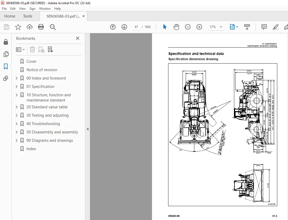
Specification and technical data 67
Specification dimension drawing 67
Specifications 68
Weight table 71
Table of fuel, coolant and lubricants 73
10 Structure, function and maintenance standard 75
Engine and cooling system 78
Engine mount and transmission mount 78
Damper 80
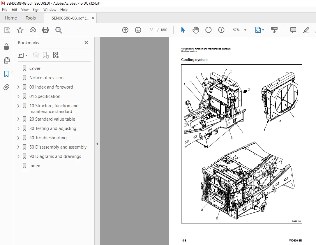
Cooling system 82
Cooling fan pump 86
Cooling fan motor 94
Power train 100
Power train 100
Power train system diagram 101
Torque converter and transmission piping diagram 102
Torque converter 104
Modulation clutch 113
Torque converter regulator valve 114
Transmission 116
Transfer 136
Transmission control valve 138
ECMV 140
Main relief valve and torque converter relief valve 147
Lubrication relief valve 149
Torque converter oil cooler 150
Torque converter oil filter 151
Drive shaft 153
Center support 156
Axle 158
Differential 162
Limited slip differential 171
Final drive 176
Steering system 180
Steering piping diagram 180
Steering column 182
Joystick steering lever linkage 183
Joystick EPC valve 184
Lock valve 185
Steering valve 186
Rotary valve 189
Steering control valve 192
Two-way restrictor valve 208
Stop valve 209
Steering pump 210
Steering cylinder 224
Emergency steering piping diagram 225
Diverter valve 226
Emergency steering pump 234
Brake system 236
Brake piping diagram 236
Brake 238
Brake valve 242
Accumulator charge valve 250
EPC relief valve 256
Accumulator (for brake) 258
Slack adjuster 260
Parking brake 264
Parking brake solenoid valve 266
Emergency parking brake release valve 268
Brake cooling pump 269
Undercarriage and frame 270
Axle mount 270
Center hinge pin 275
Hydraulic system 278
Hydraulic piping diagram 278
Work equipment control lever linkage 280
Hydraulic tank 282
Work equipment pump 284
Control valve 304
CLSS 318
Functions and operation by valve 322
Accumulator (for PPC circuit) 332
Triple pump 333
Work equipment 334
Work equipment linkage 334
Cutting edge and end bit 337
Work equipment lubrication 339
Hydraulic cylinder 342
Cab and its attachments 344
ROPS cab 344
Air conditioner 346
Electrical system 350
Machine monitor system 350
Machine monitor 356
Work equipment control system 404
Transmission controller system 430
Electric transmission control 462
Engine starting/stopping circuit 464
Parking brake circuit 467
Sensor 471
VHMS controller related 491
Electric lever (Work equipment) 497
20 Standard value table 501
Standard service value table 503
Standard service value table for engine 503
Standard service value table for chassis 504
30 Testing and adjusting 513
Related information on testing and adjusting 516
Tools for testing, adjusting, and troubleshooting 516
Engine and cooling system 521
Measuring engine speed 521
Measuring exhaust gas color 523
Measuring exhaust temperature 524
Adjusting valve clearance 526
Testing compression pressures 528
Measuring blowby pressure 531
Measuring engine oil pressure 532
Measuring intake air (boost) pressure 533
Handling fuel system equipment 534
Releasing residual pressure in fuel system 534
Testing fuel pressures 535
Testing return rate and leakage 536
Bleeding air from fuel circuit 539
Testing leakage in fuel system 541
Handling reduced cylinder mode operation 542
Handling no-injection cranking operation 542
Handling controller voltage circuit 543
Replacing and adjusting alternator and air conditioner compressor belt tension 544
Power train 545
Adjusting modulation clutch speed sensor and speed sensor 545
Measuring directional lever and gear shift lever (Steering wheel specification) 547
Testing and adjusting power train oil pressure 548
Flushing procedure for torque converter and transmission hydraulic circuit 562
Method of moving machine when transmission valve is broken 564
Moving method of machine disabled by short-to-power failure in work equipment potentiometer 566
Steering system 568
Adjusting steering stop valve 568
Measuring operating effort of AJSS lever (AJSS specification) 569
Testing and adjusting AJSS lever angle sensor and frame angle sensor (AJSS specification) 570
Testing and adjusting steering stopper bolt (AJSS specification) 572
Testing and adjusting steering wheel (Steering wheel specification) 574
Testing steering oil pressure 576
Bleeding air from steering cylinder circuit 580
Testing hydraulic drive fan 581
Bleeding air from hydraulic drive fan circuit 584
Brake system 586
Measuring brake pedal 586
Measuring brake performance 587
Testing and adjusting accumulator charge pressure 588
Testing of accumulator nitrogen gas pressure and procedure for charging brake accumulator with nitrogen gas 590
Testing wheel brake oil pressure 598
Measuring wear of wheel brake disc 600
Bleeding air from wheel brake circuit 601
Releasing residual pressure in brake accumulator circuit 602
Testing parking brake performance 603
Measuring parking brake oil pressure 604
Testing wear of parking brake disc 607
Method of releasing parking brake manually 608
Hydraulic system 609
Measuring and adjusting work equipment control lever 609
Measuring work equipment oil pressure 610
Releasing residual pressure in work equipment circuit 615
Bleeding air from work equipment circuit 617
Cab and its attachments 618
Moving machine for removing operator cab 618
Electrical system 620
Preparations for work on troubleshooting of electric system 620
Procedure for testing diodes 624
Machine monitor-based adjustment at replacement, disassembly and assembly, and additional installation for each sensor and controller 625
Special functions of machine monitor (EMMS) 629
VHMS controller initial setting procedure 698
Precautions for replacing VHMS controller 720
Pm-clinic 726
Pm-clinic inspection table 726
40 Troubleshooting 729
Related information on troubleshooting 737
Points to remember when performing troubleshooting 737
How to proceed in troubleshooting 739
Testing before troubleshooting 741
Classification and procedures of troubleshooting 742
Failure codes list 746
Information in troubleshooting table 758
Troubleshooting method for disconnecting wiring harness of pressure sensor system 760
Connection table for connector pin numbers 763
T- branch box and T- branch adapter table 799
Fuse locations 802
Troubleshooting by failure code (Display of code) 805
Failure code [1500L0] TORQFLOW transmission: Double meshing 805
Failure code [15B0NX] Transmission Oil Filter Clogging 806
Failure code [15SAL1] ECMV F clutch: When command current is OFF, fill signal is ON 808
Failure code [15SALH] ECMV F clutch: When command current is ON, fill signal is OFF 810
Failure code [15SBL1] ECMV R clutch: When command current is OFF, fill signal is ON 812
Failure code [15SBLH] ECMV R clutch: When command current is ON, fill signal is OFF 814
Failure code [15SEL1] ECMV (1): When command current is OFF, fill signal is ON 816
Failure code [15SELH] ECMV (1): When command current is ON, fill signal is OFF 818
Failure code [15SFL1] ECMV (2): When command current is OFF, fill signal is ON 820
Failure code [15SFLH] ECMV (2): When command current is ON, fill signal is OFF 822
Failure code [15SGL1] ECMV (3): When command current is OFF, fill signal is ON 824
Failure code [15SGLH] ECMV (3): When command current is ON, fill signal is OFF 826
Failure code [15SHL1] ECMV (4): When command current is OFF, fill signal is ON 828
Failure code [15SHLH] ECMV (4): When command current is ON, fill signal is OFF 830
Failure code [15W0NT] Transmission modulation clutch: Overheating 832
Failure code [2F00MA] Parking brake: Malfunction 833
Failure code [2G42ZG] Front Accumulator Oil Pressure Low 836
Failure code [2G43ZG] Rear Accumulator Oil Pressure Low 838
Failure code [A000N1] (or VHMS_LED display: “n2” → “01”) Engine: Overrun 841
Failure code [AA1ANX] Air Cleaner Clogging 842
Failure code [AB00L6] Alternator: Signal disagrees with run and stop of engine 844
Failure code [AB00MA] Alternator: Malfunction 846
Failure code [B@BAZG] Engine oil pressure: Low error 848
Failure code [B@BAZK] Eng Oil Level Low 849
Failure code [B@BCNS] Engine coolant temperature: Overheating 850
Failure code [B@BCZK] Engine coolant level low 852
Failure code [B@C7NS] Brake oil overheating 854
Failure code [b@CENS] Torque converter oil overheating 855
Failure code [B@CENS] Torque converter oil overheating 856
Failure code [B@GAZK] Low Battery Fluid Level 857
Failure code [B@HANS] Hyd Oil Overheat 858
Failure code [CA111] Abnormality in engine controller 860
Failure code [CA115] Engine Ne or Bkup speed sensor error 863
Failure code [CA122] Charge (boost) pressure sensor high error 864
Failure code [CA123] Charge (boost) pressure sensor low error 866
Failure code [CA131] Throttle sensor high error 868
Failure code [CA132] Throttle sensor low error 871
Failure code [CA135] Engine oil pressure sensor high error 874
Failure code [CA141] Engine oil pressure sensor low error 876
Failure code [CA144] Coolant temperature sensor high error 878
Failure code [CA145] Coolant temperature sensor low error 880
Failure code [CA153] Charge (boost) temperature sensor high error 882
Failure code [CA154] Charge (boost) temperature sensor low error 884
Failure code [CA187] Sensor power supply 2 low error 886
Failure code [CA212] Engine oil temperature sensor high error 888
Failure code [CA213] Engine oil temperature sensor low error 890
Failure code [CA221] Atmospheric pressure sensor high error 892
Failure code [CA222] Atmospheric pressure sensor low error 894
Failure code [CA227] Sensor power supply 2 high error 896
Failure code [CA234] Engine overspeed 897
Failure code [CA238] Ne speed sensor power supply error 898
Failure code [CA263] Fuel temperature sensor high error 900
Failure code [CA265] Fuel temperature sensor low error 902
Failure code [CA271] PCV1 Short circuit 904
Failure code [CA272] PCV1 Disconnection 905
Failure code [CA273] PCV2 Short circuit 906
Failure code [CA274] PCV2 Disconnection 907
Failure code [CA322] Injector #1 open/short error 908
Failure code [CA323] Injector #5 open/short error 910
Failure code [CA324] Injector #3 open/short error 912
Failure code [CA325] Injector #6 open/short error 914
Failure code [CA331] Injector #2 open/short error 916
Failure code [CA332] Injector #4 open/short error 918
Failure code [CA342] Calibration code inconsistency 920
Failure code [CA351] Injectors drive circuit error 921
Failure code [CA352] Sensor power supply 1 low error 922
Failure code [CA386] Sensor power supply 1 high error 924
Failure code [CA431] Idle validation switch error 925
Failure code [CA432] Idle validation action error 928
Failure code [CA441] Battery voltage low error 931
Failure code [CA442] Battery voltage high error 932
Failure code [CA449] Common rail pressure high error 2 933
Failure code [CA451] Common rail pressure sensor high error 934
Failure code [CA452] Common rail pressure sensor low error 936
Failure code [CA553] Common rail pressure high error 1 938
Failure code [CA554] Common rail pressure sensor in range error 939
Failure code [CA559] Supply pump pressure very low error 1 940
Failure code [CA689] Engine Ne speed sensor error 944
Failure code [CA731] Engine Bkup speed sensor phase error 946
Failure code [CA757] All continuous data lost error 947
Failure code [CA778] Engine Bkup speed sensor error 948
Failure code [CA1633] KOMNET datalink timeout error 950
Failure code [CA2185] Throttle sensor supply voltage high error 952
Failure code [CA2186] Throttle sensor power supply low error 954
Failure code [CA2249] Supply pump pressure very low error 2 956
Failure code [CA2555] Intake air heater relay open circuit error 958
Failure code [CA2556] Intake air heater relay short circuit error 960
Failure code [D191KA] AJSS neutral safety relay open circuit 962
Failure code [D191KB] AJSS neutral safety relay short circuit 964
Failure code [D198KA] Transmission oil pressure bypass solenoid: Disconnection 966
Failure code [D198KB] Transmission oil pressure bypass solenoid: Short circuit 967
Failure code [D198KY] Transmission oil pressure bypass solenoid: Short circuit with power supply line 968
Failure code [D5ZHKA] Terminal C signal open circuit 970
Failure code [D5ZHKB] Terminal C signal short circuit 972
Failure code [D5ZHKZ] Terminal C signal open or short circuit 974
Failure code [D5ZHL6] Terminal C signal disagrees with run and stop of engine 976
Failure code [DA80L4] Auto-greasing controller disagrees with ON/OFF signal 978
Failure code [DAF3KK] Machine monitor: Source voltage low (input) 980
Failure code [DAF5KP] Machine monitor: Output voltage low 982
Failure code [DAFRKR] CAN communication with machine monitor: Communication error (Abnormality in target component system) 984
Failure code [DAQ0KK] Transmission controller: Source voltage low 985
Failure code [DAQ0KT] Transmission controller: Defect in controller 988
Failure code [DAQ2KK] Transmission controller load power supply line: Source voltage low (Input) 990
Failure code [DAQ9KQ] Transmission controller model selection: Model selection signal disagreement 993
Failure code [DAQRKR] CAN communication with transmission controller: Communication error (Abnormality in target component system) 994
Failure code [DAQRMA] Transmission controller (Option setting): Malfunction 999
Failure code [DB2RKR] CAN communication from engine controller: Communication error (Abnormality in target component system)1000
Failure code [DB90KK] Work equipment controller: Source voltage low (input)1003
Failure code [DB90KT] Work equipment controller: Defect in controller1006
Failure code [DB92KK] Work equipment controller load power supply line: Source voltage low (input)1007
Failure code [DB95KX] Work equipment controller power supply output: Out of range1010
Failure code [DB99KQ] Work equipment controller model selection: Model selection signal disagreement1012
Failure code [DB9RKR] CAN communication with work equipment controller: Communication error (Abnormality in target component system)1013
Failure code [DB9RMA] Work equipment controller (Option setting): Malfunction1014
Failure code [DB9RMC] CAN communication with transmission controller: Malfunction1015
Failure code [DBB0KK] or change of VHMS_LED display from “n9” to “01” (VHMS controller: Source voltage low (input))1016
Failure code [DBB0KQ] or change of VHMS_LED display from “nF” to “11” (VHMS controller: Disagreement of model selection signals)1018
Failure code [DBB3KK] or change of VHMS_LED display from “n9” to “05” (VHMS controller battery power supply: Source voltage low (input))1020
Failure code [DBB5KP] or change of VHMS_LED display from “n9” to “04” (VHMS controller 5 V power supply output: Output voltage low)1022
Failure code [DBB6KP] or change of VHMS_LED display from “n9” to “02” (VHMS controller 24V power supply output: Output voltage low)1024
Failure code [DBB7KP] or change of VHMS_LED display from “n9” to “03” (VHMS controller 12V power supply output: Output voltage low)1026
Failure code [DBBQKR] or change of VHMS_LED display from “n8” to “02” (CAN communication of VHMS controller: Communication error (Abnormality in target component system))1028
Failure code [DD15LD] t switch (Panel switch 1): Switch is kept pressed for long time1030
Failure code [DD16LD] U switch (Panel switch 2): Switch is kept pressed for long time1032
Failure code [DD17LD] < switch (Panel switch 3): Switch is kept pressed for long time1034
Failure code [DD18LD] > switch (Panel switch 4): Switch is kept pressed for long time1036
Failure code [DDA7L4] RPM set ON/OFF switch: ON-OFF signals disagree1038
Failure code [DDA8KB] RPM set idle-up/down selector switch (idle-up): Short circuit1040
Failure code [DDA9KB] RPM set idle-up/down selector switch (idle-down): Short circuit1043
Failure code [DDB6L4] Parking brake switch (Neutralizer): ON/OFF signals disagree1046
Failure code [DDD1LD] Pitch operation switch: Switch is kept pressed for long time1050
Failure code [DDDBKA] Traction adjustment dial: Disconnection1052
Failure code [DDDBKB] Traction adjustment dial: Short circuit1054
Failure code [DDE5MA] Emergency steering drive switch: Malfunction1056
Failure code [DDK4KA] AJSS FNR switch: Disconnection1058
Failure code [DDK4KB] AJSS FNR switch: Short circuit1060
Failure code [DDK5L4] AJSS shift-up/down switch: ON/OFF signals disagree1062
Failure code [DDK6KA] FNR lever switch: Disconnection1065
Failure code [DDK6KB] FNR lever switch: Short circuit1068
Failure code [DDP5KA] Lock detection pressure switch of steering lock lever: Disconnection1070
Failure code [DDT0L4] Shift mode selector switch: ON/OFF signals disagree1072
Failure code [DDW9LD] Kick-down switch: Switch is kept pressed for long time1074
Failure code [DDWLLD] Hold switch: Switch is kept pressed for long time1076
Failure code [DF10KA] Transmission shift lever switch: Disconnection1078
Failure code [DF10KB] Transmission shift lever switch: Short circuit1082
Failure code [DGE5KX] (or VHMS_LED display: “n4” → “01”) Atmospheric temperature sensor: Out of input signal range1084
Failure code [DGF1KA] Transmission oil temperature sensor: Disconnection1086
Failure code [DGF1KB] Transmission oil temperature sensor: Short circuit1088
Failure code [DGH2KX] Hydraulic oil temperature sensor: Out of input signal range1090
Failure code [DGR2KA] Rear brake oil temperature sensor: Disconnection1092
Failure code [DGR2KX] Rear brake oil temperature sensor: Out of input signal range1094
Failure code [DGT1KA] Torque converter oil temperature sensor: Disconnection1096
Failure code [DGT1KB] Torque converter oil temperature sensor: Short circuit1098
Failure code [DGT1KX] Torque converter oil temperature sensor: Out of input signal range)1100
Failure code [DGT4KA] (or VHMS_LED display: “n3” → “12”) Exhaust gas temperature sensor (F): Disconnection1102
Failure code [DGT4KB] (or VHMS_LED display: “n3” → “11”) Exhaust gas temperature sensor (F): Short circuit1105
Failure code [DGT5KA] (or VHMS_LED display: “n3” → “22”) Exhaust gas temperature sensor (R): Disconnection1108
Failure code [DGT5KB] (or VHMS_LED display: “n3” → “21”) Exhaust gas temperature sensor (R): Short circuit1111
Failure code [DH21KA] Work equipment pump oil pressure sensor: Disconnection1114
Failure code [DH21KB] Work equipment pump oil pressure sensor: Short circuit1116
Failure code [DHE5KB] (or VHMS_LED display: “n3” → “32”) Blow-by pressure sensor: Short circuit1118
Failure code [DHE5KY] (or VHMS_LED display: “n3” → “31”) Blow-by pressure sensor: Short circuit with power supply line1120
Failure code [DHT2L6] Transmission filter clogging sensor: Signal disagrees with operating state of engine1122
Failure code [DHT8KX] (or VHMS_LED display: “n5” → “33”) Steering oil pressure sensor: Out of input signal range1124
Failure code [DHTBKA] Modulation clutch oil pressure sensor: Disconnection1128
Failure code [DHTBKB] Modulation clutch oil pressure sensor: Short circuit1130
Failure code [DHU2KX] (or VHMS_LED display: “n7” → “11”) Front brake oil pressure sensor (F): Out of input signal range1132
Failure code [DHU3KX] (or VHMS_LED display: “n7” → “12”) Rear brake oil pressure sensor (R): Out of input signal range1134
Failure code [DK30KA] AJSS lever angle sensor: Disconnection1136
Failure code [DK30KY] AJSS lever angle sensor: Short circuit with power supply line1138
Failure code [DK59KA] Lift EPC lever potentiometer (Main): Disconnection1140
Failure code [DK59KY] Lift EPC lever potentiometer (Main): Short circuit with power supply line1144
Failure code [DK59L8] Lift EPC lever potentiometer (Main): Analog signals disagree1146
Failure code [DK5AKA] Lift EPC lever potentiometer (Sub): Disconnection1149
Failure code [DK5AKY] Lift EPC lever potentiometer (Sub): Short circuit with power supply line1152
Failure code [DK5BKA] Tilt & pitch EPC lever potentiometer (Main): Disconnection1154
Failure code [DK5BKY] Tilt & pitch EPC lever potentiometer (Main): Short circuit with power supply line1158
Failure code [DK5BL8] Tilt & pitch EPC lever potentiometer (Main): Analog signals disagree1160
Failure code [DK5CKA] Tilt & pitch EPC lever potentiometer (Sub): Disconnection1163
Failure code [DK5CKY] Tilt & pitch EPC lever potentiometer (Sub): Short circuit with power supply line1166
Failure code [DKD0KA] Frame angle sensor: Disconnection1168
Failure code [DKD0KY] Frame angle sensor: Short circuit with power supply line1170
Failure code [DKD0KZ] AJSS lever and frame angle sensor: Disconnection or short circuit1172
Failure code [DLFAKA] Modulation clutch output shaft speed sensor: Disconnection1176
Failure code [DLFALC] Modulation clutch output shaft speed sensor: Speed signals disagree1178
Failure code [DLT3KA] Transmission output shaft speed sensor (2): Disconnection1180
Failure code [DLT3LC] Transmission output shaft speed sensor (2): Speed signals disagree1182
Failure code [DLT4KB] Transmission output shaft speed sensor (1): Short circuit1184
Failure code [DLT4KX] Transmission output shaft speed sensor (1): Out of input signal range1186
Failure code [DV00KB] Alarm buzzer: Short circuit1188
Failure code [DW4PKA] Blade raise EPC solenoid: Disconnection1190
Failure code [DW4PKB] Blade raise EPC solenoid: Short circuit1192
Failure code [DW4PKY] Blade raise EPC solenoid: Short circuit with power supply line1193
Failure code [DW4QKA] Blade lower EPC solenoid: Disconnection1194
Failure code [DW4QKB] Blade lower EPC solenoid: Short circuit1195
Failure code [DW4QKY] Blade lower EPC solenoid: Short circuit with power supply line1196
Failure code [DW4RKA] Tilt & pitch EPC solenoid: Disconnection1197
Failure code [DW4RKB] Tilt & pitch EPC solenoid: Short circuit1198
Failure code [DW4RKY] Tilt & pitch EPC solenoid: Short circuit with power supply line1199
Failure code [DW4SKA] Tilt & pitch EPC solenoid: Disconnection1200
Failure code [DW4SKB] Tilt & pitch EPC solenoid: Short circuit1201
Failure code [DW4SKY] Tilt & pitch EPC solenoid: Short circuit with power supply line1202
Failure code [DW7BKA] Fan reverse solenoid: Disconnection1204
Failure code [DW7BKB] Fan reverse solenoid: Short circuit1206
Failure code [DW7BKY] Fan reverse solenoid: Short circuit with power supply line1208
Failure code [DWM1KA] Work equipment neutral lock solenoid: Disconnection1210
Failure code [DWM1KB] Work equipment neutral lock solenoid: Short circuit1212
Failure code [DWM1KY] Work equipment neutral lock solenoid: Short circuit with power supply line1214
Failure code [DWN7KA] Blade float magnet detent solenoid: Disconnection1216
Failure code [DWN7KB] Blade float magnet detent solenoid: Short circuit1218
Failure code [DWN7KY] Blade float magnet detent solenoid: Short circuit with power supply line1220
Failure code [DWNFKA] Modulation clutch cut-off release solenoid: Disconnection1222
Failure code [DWNFKB] Modulation clutch cut-off release solenoid: Short circuit1224
Failure code [DWNFKY] Modulation clutch cut-off release solenoid: Short circuit with power source line1226
Failure code [DX16KA] Fan pump EPC solenoid: Disconnection1228
Failure code [DX16KB] Fan pump EPC solenoid: Short circuit1229
Failure code [DX16KY] Fan pump EPC solenoid: Short circuit with power supply line1230
Failure code [DXA1KA] Pump PC-EPC solenoid: Disconnection1231
Failure code [DXA1KB] Pump PC-EPC solenoid: Short circuit1232
Failure code [DXF0KA] AJSS EPC solenoid: Disconnection1233
Failure code [DXF0KB] AJSS EPC solenoid: Short circuit1234
Failure code [DXH1KA] Lockup ECMV solenoid: Disconnection1236
Failure code [DXH1KB] Lockup ECMV solenoid: Short circuit1238
Failure code [DXH1KY] Lockup ECMV solenoid: Short circuit with power supply line1240
Failure code [DXH4KA] 1st clutch ECMV solenoid: Disconnection1242
Failure code [DXH4KB] 1st clutch ECMV solenoid: Short circuit1244
Failure code [DXH4KY] 1st clutch ECMV solenoid: Short circuit with power supply line1246
Failure code [DXH5KA] 2nd clutch ECMV solenoid: Disconnection1248
Failure code [DXH5KB] 2nd clutch ECMV solenoid: Short circuit1250
Failure code [DXH5KY] 2nd clutch ECMV solenoid: Short circuit with power supply line1252
Failure code [DXH6KA] 3rd clutch ECMV solenoid: Disconnection1254
Failure code [DXH6KB] 3rd clutch ECMV solenoid: Short circuit1256
Failure code [DXH6KY] 3rd clutch ECMV solenoid: Short circuit with power supply line1258
Failure code [DXH7KA] R clutch ECMV solenoid: Disconnection1260
Failure code [DXH7KB] R clutch ECMV solenoid: Short circuit1262
Failure code [DXH7KY] R clutch ECMV solenoid: Short circuit with power supply line1264
Failure code [DXH8KA] F clutch ECMV solenoid: Disconnection1266
Failure code [DXH8KB] F clutch ECMV solenoid: Short circuit1268
Failure code [DXH8KY] F clutch ECMV solenoid: Short circuit with power supply line1270
Failure code [DXHHKA] 4th clutch ECMV solenoid: Disconnection1272
Failure code [DXHHKB] 4th clutch ECMV solenoid: Short circuit1274
Failure code [DXHHKY] 4th clutch ECMV solenoid: Short circuit with power supply line1276
Failure code [DXHJKA] RH pitch REAR EPC solenoid: Disconnection1278
Failure code [DXHJKB] RH pitch REAR EPC solenoid: Short circuit1279
Failure code [DXHJKY] RH pitch REAR EPC solenoid: Short circuit with power supply line1280
Failure code [DXHKKA] RH pitch FORWARD EPC solenoid: Disconnection1281
Failure code [DXHKKB] RH pitch FORWARD EPC solenoid: Short circuit1282
Failure code [DXHKKY] RH pitch FORWARD EPC solenoid: Short circuit with power supply line1283
Failure code [DXHPKA] Modulation clutch solenoid: Disconnection1284
Failure code [DXHPKB] Modulation clutch solenoid: Short circuit1286
Failure code [DXHPKY] Modulation clutch solenoid: Short circuit with power source line1288
Failure code [DXHPMA] Modulation clutch solenoid: Malfunction1290
Failure code [F@BBZL] (or VHMS_LED display: “n3” → “38”) Blow-by pressure: High error1292
Failure code [F@BYNR] (or VHMS_LED display: “n3” → “62”) Exhaust gas temperature (F): Abnormal heat1294
Failure code [F@BYNS] (or VHMS_LED display: “n3” → “61”) Exhaust gas temperature (F): Overheat1296
Failure code [F@BZNR] (or VHMS_LED display: “n3” → “72”) Exhaust gas temperature (R): abnormal heat1298
Failure code [F@BZNS] (or VHMS_LED display “n3” → “71”) Exhaust gas temperature (R): Overheat1300
Troubleshooting of electrical system (E-mode)1302
E-1 Engine does not start1302
E-2 Wiper does not operate1312
E-3 Windshield washer does not operate1320
E-4 Headlamp, clearance lamp, tail lamp, and license lamp do not light up or go off1326
E-5 Working lamp does not light up or go off1342
E-6 Step lamp does not light up or go off1350
E-7 Turn signal lamp and hazard lamp do not light up or go off1352
E-8 Brake lamp does not light or it keeps lighting up1362
E-9 Backup lamp does not light or it keeps lighting up1366
E-10 Backup buzzer does not sound or it keeps sounding1370
E-11 Horn does not sound or it keeps sounding1374
E-12 Alarm buzzer does not sound or it keeps sounding1378
E-13 Air conditioner does not operate or stop1380
E-14 Electric priming pump does not operate or does not stop automatically1382
E-15 When starting switch is turned to ON position, machine monitor displays nothing1384
Troubleshooting of hydraulic and mechanical system (H-mode)1388
Method of using troubleshooting chart1388
Table of failure modes and causes1390
H-1 Machine does not start1394
H-2 Torque converter lockup is not switched (engine stalls)1396
H-3 Torque converter lockup is not turned on1397
H-4 Travel speed is slow, thrusting force is weak, uphill traveling power is weak, and gear is not shifted1398
H-5 Shocks are large at the times of starting and shifting gear1400
H-6 Time lag is large at the times of starting and shifting gear1402
H-7 Torque converter oil temperature is high1404
H-8 Steering does not turn [machine with steering wheel]1405
H-9 Steering does not turn [machine with AJSS]1406
H-10 Turning, response of steering is poor [machine with steering wheel]1407
H-11 Turning, response of AJSS is poor [machine with AJSS]1408
H-12 Steering is heavy [machine with steering wheel]1409
H-13 When machine turns, it shakes or makes large shocks [machine with steering wheel]1410
H-14 When machine turns, it shakes or makes large shocks [machine with AJSS]1411
H-15 Wheel brake does not work or does not work well1412
H-16 Wheel brake is not released or it drags1413
H-17 Parking brake does not work or does not work well1414
H-18 Parking brake is not released or it drags (including emergency release system)1415
H-19 Blade does not rise1416
H-20 Blade speed is low or rising force of lift is insufficient1417
H-21 When rising, blade comes to move slowly at specific height1418
H-22 Lift cylinder cannot hold down blade (Blade floats)1418
H-23 Hydraulic drifts of blade occur often1418
H-24 Blade wobbles during operation1418
H-25 Blade does not tilt and pitch1419
H-26 Blade speed is low or tilt and pitch force is insufficient1420
H-27 Blade comes to operate slowly in the midst of tilt and pitch1421
H-28 Tilt & pitch cylinder cannot hold down blade1421
H-29 Hydraulic drifts of blade occur often1421
H-30 Blade wobbles during travel when loaded (Work equipment valve is set to “HOLD”)1421
H-31 During operation of machine, engine speed lowers remarkably or engine stalls1422
H-32 Large shocks are made when work equipment starts and stops1422
H-33 When work equipment circuit is relieved singly, other work equipment moves1422
H-34 Fan speed is abnormal (Fan sound and vibration are abnormally large or engine overheats)1423
Troubleshooting of engine (S-mode)1425
Method of using troubleshooting chart1425
S-1 Engine does not start easily1428
S-2 Engine does not start1429
S-3 Engine does not pick up smoothly1432
S-4 Engine stops during operation1433
S-5 Engine does not rotate smoothly (Hunting occurs)1434
S-6 Engine lacks output (or lacks power)1435
S-7 Exhaust smoke is black (Incomplete combustion)1436
S-8 Oil is consumed much (or exhaust gas color is blue)1437
S-9 Engine oil becomes contaminated quickly1438
S-10 Fuel consumption is excessive1439
S-11 Coolant contains oil (blows back or reduces)1440
S-12 Oil pressure drops1441
S-13 Oil level rises (Water, fuel in oil)1442
S-14 Coolant temperature rises too high (Overheating)1443
S-15 Abnormal noise is made1444
S-16 Vibration is excessive1445
S-17 Air cannot be bled from fuel circuit1446
50 Disassembly and assembly1449
General information on disassembly and assembly1452
How to read this manual1452
Coating materials list1454
Special tools list1457
Sketches of special tools1461
Engine and cooling system1469
Removal and installation of engine assembly1469
Removal and installation of radiator assembly1472
Removal and installation of air aftercooler1477
Removal and installation of cooling fan and fan motor assembly1478
Removal and installation of damper assembly1480
Disassembly and assembly of damper assembly1482
Removal and installation of fuel tank assembly1486
Removal and installation of engine hood assembly1488
Removal and installation of bulkhead assembly1490
Removal and installation of fuel supply pump assembly1494
Removal and installation of cylinder head assembly1500
Removal and installation of fuel injector assembly1515
Removal and installation of engine front seal1519
Removal and installation of engine rear seal1522
Power train1526
Removal and installation of parking brake assembly1526
Removal and installation of torque converter and transmission assembly1528
Disassembly and assembly of torque converter assembly1533
Disassembly and assembly of transmission assembly1560
Disassembly and assembly of transfer assembly1587
Disassembly and assembly of parking brake assembly1604
Removal and installation of front axle assembly1611
Removal and installation of rear axle assembly1613
Removal and installation of center support assembly1615
Disassembly and assembly of center support assembly1617
Disassembly and assembly of differential assembly1621
Removal and installation of final drive carrier assembly1635
Disassembly and assembly of final drive carrier assembly1637
Removal and installation of front final drive brake assembly1638
Disassembly and assembly of final drive assembly1640
Brake system1643
Disassembly and assembly of brake assembly1643
Removal and installation of brake valve assembly1651
Disassembly and assembly of accumulator and charge valve assembly1652
Disassembly and assembly of slack adjustor assembly1655
Undercarriage and frame1657
Removal and installation of center hinge pin1657
Removal and installation of counterweight assembly1664
Hydraulic system1665
Removal and installation of hydraulic tank assembly1665
Removal and installation of hydraulic pump assembly1667
Removal and installation of control valve assembly1671
Disassembly and assembly of control valve assembly1673
Removal and installation of steering valve assembly1678
Disassembly and assembly of hydraulic cylinder assembly1679
Work equipment1684
Removal and installation of work equipment assembly1684
Cab and its attachments1688
Removal and installation of operator’s cab assembly1688
Removal and installation of operator’s cab glass (stuck glass)1692
Removal and installation of floor frame assembly1700
Disassembly and assembly of operator’s seat assembly1703
Removal and installation of air conditioner unit assembly1736
Removal and installation of AJSSlever switch assembly1739
Electrical system1745
Removal and installation of engine controller assembly1745
Removal and installation of transmission controller assembly1747
Removal and installation of loader controller assembly1747
Removal and installation of VHMS controller assembly1748
Removal and installation of machine monitor assembly1749
90 Diagrams and drawings1753
Hydraulic diagrams and drawings1755
Symbols used in hydraulic circuit diagrams1755
Power train hydraulic circuit diagram1757
Brake hydraulic circuit diagram1758
Work equipment hydraulic circuit diagram1761
Electrical diagrams and drawings1763
Symbols used in electric circuit diagrams1763
Air conditioner electrical circuit diagram1767
Electrical circuit diagram1769
KOMTRAX electrical circuit diagram1789
Connector list and layout1791
Index1793
S.M 30/12/24