Komatsu WHEEL DOZER WD600-6R Shop Manual SEN06588-07 PDF
$37.95
Komatsu WHEEL DOZER WD600-6R Shop Manual SEN06588-07 – PDF DOWNLOAD
SERIAL NUMBERS 60001 and up
Description
Komatsu WHEEL DOZER WD600-6R Shop Manual SEN06588-07 – PDF DOWNLOAD
FILE DETAILS:
Komatsu WHEEL DOZER WD600-6R Shop Manual SEN06588-07 – PDF DOWNLOAD
Language : English
Pages :1830
Downloadable : Yes
File Type : PDF
IMAGES PREVIEW OF THE MANUAL:
DESCRIPTION:
Komatsu WHEEL DOZER WD600-6R Shop Manual SEN06588-07 – PDF DOWNLOAD
SERIAL NUMBERS 60001 and up
How to Read the Shop Manual
• Some of the attachments and options described in this shop manual may not be available in some areas. If
they are required, consult your Komatsu distributor.
• The materials and specifications are subject to change without notice.
• Shop Manuals are available for “machine part” and “engine part”. For the engine unit, see the shop manual
for the machine which has the same engine model.
• Actual machine may differ from the images which are contained in this manual. A typical model is shown in
the illustrations of this shop manual.
• The caution lamps, pilot lamps, and symbols of the switches on the machine monitor can be different in
accordance with the machine.
• For details of the symbols shown on the machine monitor, see Structure and Operation, “Caution
Lamps Shown on Machine Monitor” and “Pilot Lamps Shown on Machine Monitor”.
• For details of the switches of the machine monitor, see Testing and Adjusting, “Set and Operate Machine
Monitor”.
• For details of the switches, see the “Operation and Maintenance Manual”.
• All “AdBlue/DEF” shown on the machine monitor is referred to as “DEF” in the shop manual. Some machine
monitors installed to the product show “DEF” as “AdBlue/DEF” in the service mode. Thus, be sure to recognize
that “DEF” and “AdBlue/DEF” are the same when you read the shop manual.
REMARK
The illustrations in the shop manual reproduce the display of the machine monitor. They are not always the
same as the terminology in the shop manual.
Composition of the Shop Manual
This shop manual contains technical information necessary to perform services in workshops. It is divided into
the following chapters for the ease of use.
00 Index and Foreword
This section describes the index, foreword, safety, and basic information.
01 Specification
This section describes the specifications of the machine.
10 Structure and Function
This section describes the structure and operation of each component with respect to each system. “Structure
and Function” is helpful in not only understanding the structure of each component but performing troubleshooting.
20 Standard Value Table
This section describes the standard values for new machine and failure criteria for testing and adjusting, and
troubleshooting. Use the standard values table to check the standard values for testing and adjusting, and judge
troubles in troubleshooting.
30 Testing and Adjusting
This section describes the measuring tools and measuring methods for testing and adjusting as well as the adjusting
method of each part. The standard values and repair limit for TESTING AND ADJUSTING are described
in “Standard Value Table”.
40 Troubleshooting
This section describes troubleshooting of failure part and its remedy method on the occurrence of the failure.
Descriptions of troubleshooting are sorted by failure mode.
This section describes the special tools, work procedures, and safety precautions necessary for removal, installation,
disassembly, and assembly of the components and parts. In addition, tightening torques, quantity, and
weight of the coating materials, lubricants, and coolant necessary to these works are shown.
60 Maintenance Standard
This section describes the maintenance standard value of each component. The maintenance standard shows
the criteria and remedies for disassembly and assembly.
80 Others
This section describes the structure and function, testing and adjusting, and troubleshooting for all of the other
components or equipment which cannot be separately classified in the appendix.
90 Circuit Diagrams
This section describes hydraulic circuit diagrams and electrical circuit diagrams.
TABLE OF CONTENTS:
Komatsu WHEEL DOZER WD600-6R Shop Manual SEN06588-07 – PDF DOWNLOAD
SERIAL NUMBERS 60001 and up
Cover 1
00 Index and foreword 3
Table of contents 4
Foreword and general information 16
Safety notice 16
How to read the shop manual 21
Explanation of terms for maintenance standard 23
Handling of electric equipment and hydraulic component 25
Handling of connectors newly used for engines 34
How to read electric wire code 37
Precautions when carrying out operation 40
Method of disassembling and connecting push-pull type coupler 43
Standard tightening torque table 46
Conversion table 50
01 Specification 55
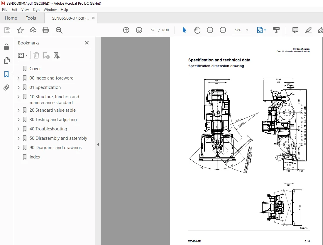
Specification and technical data 57
Specification dimension drawing 57
Specifications 58
Weight table 61
Table of fuel, coolant and lubricants 63
10 Structure, function and maintenance standard 65
Engine and cooling system 68
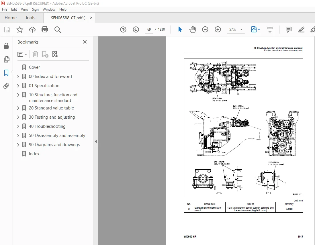
Engine mount and transmission mount 68
Damper 70
Cooling system 72
Cooling fan pump 76
Cooling fan motor 84
Power train 90
Power train 90
Power train system diagram 91
Torque converter and transmission piping diagram 92
Torque converter 94
Modulation clutch 103
Torque converter regulator valve 104
Transmission 106
Transfer 126
Transmission control valve 128
ECMV 130
Main relief valve and torque converter relief valve 137
Lubrication relief valve 139
Torque converter oil cooler 140
Torque converter oil filter 141
Drive shaft 143
Center support 146
Axle 148
Differential 152
Limited slip differential 161
Final drive 166
Steering system 170
Steering piping diagram 170
Steering column 172
Joystick steering lever linkage 173
Joystick EPC valve 174
Lock valve 175
Steering valve 176
Rotary valve 179
Steering control valve 182
Two-way restrictor valve 198
Stop valve 199
Steering pump 200
Steering cylinder 214
Emergency steering piping diagram 215
Diverter valve 216
Emergency steering pump 224
Brake system 226
Brake piping diagram 226
Brake 228
Brake valve 232
Accumulator charge valve 240
EPC relief valve 246
Accumulator (for brake) 248
Slack adjuster 250
Parking brake 254
Parking brake solenoid valve 256
Emergency parking brake release valve 258
Brake cooling pump 259
Undercarriage and frame 260
Axle mount 260
Center hinge pin 265
Hydraulic system 268
Hydraulic piping diagram 268
Work equipment control lever linkage 270
Hydraulic tank 272
Work equipment pump 274
Control valve 294
CLSS 308
Functions and operation by valve 312
Accumulator (for PPC circuit) 322
Triple pump 323
Work equipment 324
Work equipment linkage 324
Cutting edge and end bit 327
Work equipment lubrication 329
Hydraulic cylinder 332
Cab and its attachments 334
ROPS cab 334
Air conditioner 336
Electrical system 340
Machine monitor system 340
Machine monitor 346
Work equipment control system 394
Transmission controller system 420
Electric transmission control 452
Engine starting/stopping circuit 454
Parking brake circuit 457
Sensor 461
VHMS controller related 482
VHMS controller and wireless LAN system 484
Electric lever (Work equipment) 491
20 Standard value table 495
Standard service value table 497
Standard service value table for engine 497
Standard service value table for chassis 498
30 Testing and adjusting 507
Related information on testing and adjusting 510
Tools for testing, adjusting, and troubleshooting 510
Engine and cooling system 517
Measuring engine speed 517
Measuring exhaust gas color 519
Measuring exhaust temperature 520
Adjusting valve clearance 522
Testing compression pressures 524
Measuring blowby pressure 527
Measuring engine oil pressure 528
Measuring intake air (boost) pressure 529
Handling fuel system equipment 530
Releasing residual pressure in fuel system 530
Testing fuel pressures 531
Testing return rate and leakage 532
Bleeding air from fuel circuit 535
Testing leakage in fuel system 537
Handling reduced cylinder mode operation 538
Handling no-injection cranking operation 538
Handling controller voltage circuit 539
Replacing and adjusting alternator and air conditioner compressor belt tension 540
Power train 541
Adjusting modulation clutch speed sensor and speed sensor 541
Measuring directional lever and gear shift lever (Steering wheel specification) 543
Testing and adjusting power train oil pressure 544
Flushing procedure for torque converter and transmission hydraulic circuit 558
Method of moving machine when transmission valve is broken 560
Moving method of machine disabled by short-to-power failure in work equipment potentiometer 562
Steering system 564
Adjusting steering stop valve 564
Measuring operating effort of AJSS lever (AJSS specification) 565
Testing and adjusting AJSS lever angle sensor and frame angle sensor (AJSS specification) 566
Testing and adjusting steering stopper bolt (AJSS specification) 568
Testing and adjusting steering wheel (Steering wheel specification) 570
Testing steering oil pressure 572
Bleeding air from steering cylinder circuit 576
Testing hydraulic drive fan 577
Bleeding air from hydraulic drive fan circuit 580
Brake system 582
Measuring brake pedal 582
Measuring brake performance 583
Testing and adjusting accumulator charge pressure 584
Testing of accumulator nitrogen gas pressure and procedure for charging brake accumulator with nitrogen gas 586
Testing wheel brake oil pressure 594
Measuring wear of wheel brake disc 596
Bleeding air from wheel brake circuit 597
Releasing residual pressure in brake accumulator circuit 598
Testing parking brake performance 599
Measuring parking brake oil pressure 600
Testing wear of parking brake disc 603
Method of releasing parking brake manually 604
Hydraulic system 605
Measuring and adjusting work equipment control lever 605
Measuring work equipment oil pressure 606
Releasing residual pressure in work equipment circuit 611
Bleeding air from work equipment circuit 613
Cab and its attachments 614
Moving machine for removing operator cab 614
Electrical system 616
Preparations for work on troubleshooting of electric system 616
Procedure for testing diodes 620
Machine monitor-based adjustment at replacement, disassembly and assembly, and additional installation for each sensor and controller 621
Special functions of machine monitor (EMMS) 625
VHMS controller initial settingprocedure (ORBCOMM installationspecification) 694
VHMS controller initial settingprocedure (IRIDIUM installationspecification) 716
Precautions for replacing VHMS controller 738
Initialization of VHMS wireless LAN modem and downloading of data 744
Pm-clinic 752
Pm-clinic inspection table 752
40 Troubleshooting 755
Related information on troubleshooting 763
Points to remember when performing troubleshooting 763
How to proceed in troubleshooting 765
Testing before troubleshooting 767
Classification and procedures of troubleshooting 768
Failure codes list 772
Information in troubleshooting table 784
Troubleshooting method for disconnecting wiring harness of pressure sensor system 786
Connection table for connector pin numbers 789
T- branch box and T- branch adapter table 825
Fuse locations 828
Troubleshooting by failure code (Display of code) 831
Failure code [1500L0] TORQFLOW transmission: Double meshing 831
Failure code [15B0NX] Transmission Oil Filter Clogging 832
Failure code [15SAL1] ECMV F clutch: When command current is OFF, fill signal is ON 834
Failure code [15SALH] ECMV F clutch: When command current is ON, fill signal is OFF 836
Failure code [15SBL1] ECMV R clutch: When command current is OFF, fill signal is ON 838
Failure code [15SBLH] ECMV R clutch: When command current is ON, fill signal is OFF 840
Failure code [15SEL1] ECMV (1): When command current is OFF, fill signal is ON 842
Failure code [15SELH] ECMV (1): When command current is ON, fill signal is OFF 844
Failure code [15SFL1] ECMV (2): When command current is OFF, fill signal is ON 846
Failure code [15SFLH] ECMV (2): When command current is ON, fill signal is OFF 848
Failure code [15SGL1] ECMV (3): When command current is OFF, fill signal is ON 850
Failure code [15SGLH] ECMV (3): When command current is ON, fill signal is OFF 852
Failure code [15SHL1] ECMV (4): When command current is OFF, fill signal is ON 854
Failure code [15SHLH] ECMV (4): When command current is ON, fill signal is OFF 856
Failure code [15W0NT] Transmission modulation clutch: Overheating 858
Failure code [2F00MA] Parking brake: Malfunction 859
Failure code [2G42ZG] Front Accumulator Oil Pressure Low 862
Failure code [2G43ZG] Rear Accumulator Oil Pressure Low 864
Failure code [A000N1] (or VHMS_LED display: “n2” → “01”) Engine: Overrun 867
Failure code [AA1ANX] Air Cleaner Clogging 868
Failure code [AB00L6] Alternator: Signal disagrees with run and stop of engine 870
Failure code [AB00MA] Alternator: Malfunction 872
Failure code [B@BAZG] Engine oil pressure: Low error 874
Failure code [B@BAZK] Eng Oil Level Low 875
Failure code [B@BCNS] Engine coolant temperature: Overheating 876
Failure code [B@BCZK] Engine coolant level low 878
Failure code [B@C7NS] Brake oil overheating 880
Failure code [b@CENS] Torque converter oil overheating 881
Failure code [B@CENS] Torque converter oil overheating 882
Failure code [B@GAZK] Low Battery Fluid Level 883
Failure code [B@HANS] Hyd Oil Overheat 884
Failure code [CA111] Abnormality in engine controller 886
Failure code [CA115] Engine Ne or Bkup speed sensor error 889
Failure code [CA122] Charge (boost) pressure sensor high error 890
Failure code [CA123] Charge (boost) pressure sensor low error 892
Failure code [CA131] Throttle sensor high error 894
Failure code [CA132] Throttle sensor low error 897
Failure code [CA135] Engine oil pressure sensor high error 900
Failure code [CA141] Engine oil pressure sensor low error 902
Failure code [CA144] Coolant temperature sensor high error 904
Failure code [CA145] Coolant temperature sensor low error 906
Failure code [CA153] Charge (boost) temperature sensor high error 908
Failure code [CA154] Charge (boost) temperature sensor low error 910
Failure code [CA187] Sensor power supply 2 low error 912
Failure code [CA212] Engine oil temperature sensor high error 914
Failure code [CA213] Engine oil temperature sensor low error 916
Failure code [CA221] Atmospheric pressure sensor high error 918
Failure code [CA222] Atmospheric pressure sensor low error 920
Failure code [CA227] Sensor power supply 2 high error 922
Failure code [CA234] Engine overspeed 923
Failure code [CA238] Ne speed sensor power supply error 924
Failure code [CA263] Fuel temperature sensor high error 926
Failure code [CA265] Fuel temperature sensor low error 928
Failure code [CA271] PCV1 Short circuit 930
Failure code [CA272] PCV1 Disconnection 931
Failure code [CA273] PCV2 Short circuit 932
Failure code [CA274] PCV2 Disconnection 933
Failure code [CA322] Injector #1 open/short error 934
Failure code [CA323] Injector #5 open/short error 936
Failure code [CA324] Injector #3 open/short error 938
Failure code [CA325] Injector #6 open/short error 940
Failure code [CA331] Injector #2 open/short error 942
Failure code [CA332] Injector #4 open/short error 944
Failure code [CA342] Calibration code inconsistency 946
Failure code [CA351] Injectors drive circuit error 947
Failure code [CA352] Sensor power supply 1 low error 948
Failure code [CA386] Sensor power supply 1 high error 950
Failure code [CA431] Idle validation switch error 951
Failure code [CA432] Idle validation action error 954
Failure code [CA441] Battery voltage low error 957
Failure code [CA442] Battery voltage high error 958
Failure code [CA449] Common rail pressure high error 2 959
Failure code [CA451] Common rail pressure sensor high error 960
Failure code [CA452] Common rail pressure sensor low error 962
Failure code [CA553] Common rail pressure high error 1 964
Failure code [CA554] Common rail pressure sensor in range error 965
Failure code [CA559] Supply pump pressure very low error 1 966
Failure code [CA689] Engine Ne speed sensor error 970
Failure code [CA731] Engine Bkup speed sensor phase error 972
Failure code [CA757] All continuous data lost error 973
Failure code [CA778] Engine Bkup speed sensor error 974
Failure code [CA1633] KOMNET datalink timeout error 976
Failure code [CA2185] Throttle sensor supply voltage high error 978
Failure code [CA2186] Throttle sensor power supply low error 980
Failure code [CA2249] Supply pump pressure very low error 2 982
Failure code [CA2555] Intake air heater relay open circuit error 984
Failure code [CA2556] Intake air heater relay short circuit error 986
Failure code [D191KA] AJSS neutral safety relay open circuit 988
Failure code [D191KB] AJSS neutral safety relay short circuit 990
Failure code [D198KA] Transmission oil pressure bypass solenoid: Disconnection 992
Failure code [D198KB] Transmission oil pressure bypass solenoid: Short circuit 993
Failure code [D198KY] Transmission oil pressure bypass solenoid: Short circuit with power supply line 994
Failure code [D5ZHKA] Terminal C signal open circuit 996
Failure code [D5ZHKB] Terminal C signal short circuit 998
Failure code [D5ZHKZ] Terminal C signal open or short circuit1000
Failure code [D5ZHL6] Terminal C signal disagrees with run and stop of engine1002
Failure code [DA80L4] Auto-greasing controller disagrees with ON/OFF signal1004
Failure code [DAF3KK] Machine monitor: Source voltage low (input)1006
Failure code [DAF5KP] Machine monitor: Output voltage low1008
Failure code [DAFRKR] CAN communication with machine monitor: Communication error (Abnormality in target component system)1010
Failure code [DAQ0KK] Transmission controller: Source voltage low1011
Failure code [DAQ0KT] Transmission controller: Defect in controller1014
Failure code [DAQ2KK] Transmission controller load power supply line: Source voltage low (Input)1016
Failure code [DAQ9KQ] Transmission controller model selection: Model selection signal disagreement1019
Failure code [DAQRKR] CAN communication with transmission controller: Communication error (Abnormality in target component system)1020
Failure code [DAQRMA] Transmission controller (Option setting): Malfunction1025
Failure code [DB2RKR] CAN communication from engine controller: Communication error (Abnormality in target component system)1026
Failure code [DB90KK] Work equipment controller: Source voltage low (input)1029
Failure code [DB90KT] Work equipment controller: Defect in controller1032
Failure code [DB92KK] Work equipment controller load power supply line: Source voltage low (input)1033
Failure code [DB95KX] Work equipment controller power supply output: Out of range1036
Failure code [DB99KQ] Work equipment controller model selection: Model selection signal disagreement1038
Failure code [DB9RKR] CAN communication with work equipment controller: Communication error (Abnormality in target component system)1039
Failure code [DB9RMA] Work equipment controller (Option setting): Malfunction1040
Failure code [DB9RMC] CAN communication with transmission controller: Malfunction1041
Failure code [DBB0KK] or change of VHMS_LED display from “n9” to “01” (VHMS controller: Source voltage low (input))1042
Failure code [DBB0KQ] or change of VHMS_LED display from “nF” to “11” (VHMS controller: Disagreement of model selection signals)1044
Failure code [DBB3KK] or change of VHMS_LED display from “n9” to “05” (VHMS controller battery power supply: Source voltage low (input))1046
Failure code [DBB5KP] or change of VHMS_LED display from “n9” to “04” (VHMS controller 5 V power supply output: Output voltage low)1048
Failure code [DBB6KP] or change of VHMS_LED display from “n9” to “02” (VHMS controller 24V power supply output: Output voltage low)1050
Failure code [DBB7KP] or change of VHMS_LED display from “n9” to “03” (VHMS controller 12V power supply output: Output voltage low)1052
Failure code [DBBQKR] or change of VHMS_LED display from “n8” to “02” (CAN communication of VHMS controller: Communication error (Abnormality in target component system))1054
Failure code [DD15LD] t switch (Panel switch 1): Switch is kept pressed for long time1056
Failure code [DD16LD] U switch (Panel switch 2): Switch is kept pressed for long time1058
Failure code [DD17LD] < switch (Panel switch 3): Switch is kept pressed for long time1060
Failure code [DD18LD] > switch (Panel switch 4): Switch is kept pressed for long time1062
Failure code [DDA7L4] RPM set ON/OFF switch: ON-OFF signals disagree1064
Failure code [DDA8KB] RPM set idle-up/down selector switch (idle-up): Short circuit1066
Failure code [DDA9KB] RPM set idle-up/down selector switch (idle-down): Short circuit1069
Failure code [DDB6L4] Parking brake switch (Neutralizer): ON/OFF signals disagree1072
Failure code [DDD1LD] Pitch operation switch: Switch is kept pressed for long time1076
Failure code [DDDBKA] Traction adjustment dial: Disconnection1078
Failure code [DDDBKB] Traction adjustment dial: Short circuit1080
Failure code [DDE5MA] Emergency steering drive switch: Malfunction1082
Failure code [DDK4KA] AJSS FNR switch: Disconnection1084
Failure code [DDK4KB] AJSS FNR switch: Short circuit1086
Failure code [DDK5L4] AJSS shift-up/down switch: ON/OFF signals disagree1088
Failure code [DDK6KA] FNR lever switch: Disconnection1091
Failure code [DDK6KB] FNR lever switch: Short circuit1094
Failure code [DDP5KA] Lock detection pressure switch of steering lock lever: Disconnection1096
Failure code [DDT0L4] Shift mode selector switch: ON/OFF signals disagree1098
Failure code [DDW9LD] Kick-down switch: Switch is kept pressed for long time1100
Failure code [DDWLLD] Hold switch: Switch is kept pressed for long time1102
Failure code [DF10KA] Transmission shift lever switch: Disconnection1104
Failure code [DF10KB] Transmission shift lever switch: Short circuit1108
Failure code [DGE5KX] (or VHMS_LED display: “n4” → “01”) Atmospheric temperature sensor: Out of input signal range1110
Failure code [DGF1KA] Transmission oil temperature sensor: Disconnection1112
Failure code [DGF1KB] Transmission oil temperature sensor: Short circuit1114
Failure code [DGH2KX] Hydraulic oil temperature sensor: Out of input signal range1116
Failure code [DGR2KA] Rear brake oil temperature sensor: Disconnection1118
Failure code [DGR2KX] Rear brake oil temperature sensor: Out of input signal range1120
Failure code [DGT1KA] Torque converter oil temperature sensor: Disconnection1122
Failure code [DGT1KB] Torque converter oil temperature sensor: Short circuit1124
Failure code [DGT1KX] Torque converter oil temperature sensor: Out of input signal range)1126
Failure code [DGT4KA] (or VHMS_LED display: “n3” → “12”) Exhaust gas temperature sensor (F): Disconnection1128
Failure code [DGT4KB] (or VHMS_LED display: “n3” → “11”) Exhaust gas temperature sensor (F): Short circuit1131
Failure code [DGT5KA] (or VHMS_LED display: “n3” → “22”) Exhaust gas temperature sensor (R): Disconnection1134
Failure code [DGT5KB] (or VHMS_LED display: “n3” → “21”) Exhaust gas temperature sensor (R): Short circuit1137
Failure code [DH21KA] Work equipment pump oil pressure sensor: Disconnection1140
Failure code [DH21KB] Work equipment pump oil pressure sensor: Short circuit1142
Failure code [DHE5KB] (or VHMS_LED display: “n3” → “32”) Blow-by pressure sensor: Short circuit1144
Failure code [DHE5KY] (or VHMS_LED display: “n3” → “31”) Blow-by pressure sensor: Short circuit with power supply line1146
Failure code [DHT2L6] Transmission filter clogging sensor: Signal disagrees with operating state of engine1148
Failure code [DHT8KX] (or VHMS_LED display: “n5” → “33”) Steering oil pressure sensor: Out of input signal range1150
Failure code [DHTBKA] Modulation clutch oil pressure sensor: Disconnection1154
Failure code [DHTBKB] Modulation clutch oil pressure sensor: Short circuit1156
Failure code [DHU2KX] (or VHMS_LED display: “n7” → “11”) Front brake oil pressure sensor (F): Out of input signal range1158
Failure code [DHU3KX] (or VHMS_LED display: “n7” → “12”) Rear brake oil pressure sensor (R): Out of input signal range1160
Failure code [DK30KA] AJSS lever angle sensor: Disconnection1162
Failure code [DK30KY] AJSS lever angle sensor: Short circuit with power supply line1164
Failure code [DK59KA] Lift EPC lever potentiometer (Main): Disconnection1166
Failure code [DK59KY] Lift EPC lever potentiometer (Main): Short circuit with power supply line1170
Failure code [DK59L8] Lift EPC lever potentiometer (Main): Analog signals disagree1172
Failure code [DK5AKA] Lift EPC lever potentiometer (Sub): Disconnection1175
Failure code [DK5AKY] Lift EPC lever potentiometer (Sub): Short circuit with power supply line1178
Failure code [DK5BKA] Tilt & pitch EPC lever potentiometer (Main): Disconnection1180
Failure code [DK5BKY] Tilt & pitch EPC lever potentiometer (Main): Short circuit with power supply line1184
Failure code [DK5BL8] Tilt & pitch EPC lever potentiometer (Main): Analog signals disagree1186
Failure code [DK5CKA] Tilt & pitch EPC lever potentiometer (Sub): Disconnection1189
Failure code [DK5CKY] Tilt & pitch EPC lever potentiometer (Sub): Short circuit with power supply line1192
Failure code [DKD0KA] Frame angle sensor: Disconnection1194
Failure code [DKD0KY] Frame angle sensor: Short circuit with power supply line1196
Failure code [DKD0KZ] AJSS lever and frame angle sensor: Disconnection or short circuit1198
Failure code [DLFAKA] Modulation clutch output shaft speed sensor: Disconnection1202
Failure code [DLFALC] Modulation clutch output shaft speed sensor: Speed signals disagree1204
Failure code [DLT3KA] Transmission output shaft speed sensor (2): Disconnection1206
Failure code [DLT3LC] Transmission output shaft speed sensor (2): Speed signals disagree1208
Failure code [DLT4KB] Transmission output shaft speed sensor (1): Short circuit1210
Failure code [DLT4KX] Transmission output shaft speed sensor (1): Out of input signal range1212
Failure code [DV00KB] Alarm buzzer: Short circuit1214
Failure code [DW4PKA] Blade raise EPC solenoid: Disconnection1216
Failure code [DW4PKB] Blade raise EPC solenoid: Short circuit1218
Failure code [DW4PKY] Blade raise EPC solenoid: Short circuit with power supply line1219
Failure code [DW4QKA] Blade lower EPC solenoid: Disconnection1220
Failure code [DW4QKB] Blade lower EPC solenoid: Short circuit1221
Failure code [DW4QKY] Blade lower EPC solenoid: Short circuit with power supply line1222
Failure code [DW4RKA] Tilt & pitch EPC solenoid: Disconnection1223
Failure code [DW4RKB] Tilt & pitch EPC solenoid: Short circuit1224
Failure code [DW4RKY] Tilt & pitch EPC solenoid: Short circuit with power supply line1225
Failure code [DW4SKA] Tilt & pitch EPC solenoid: Disconnection1226
Failure code [DW4SKB] Tilt & pitch EPC solenoid: Short circuit1227
Failure code [DW4SKY] Tilt & pitch EPC solenoid: Short circuit with power supply line1228
Failure code [DW7BKA] Fan reverse solenoid: Disconnection1230
Failure code [DW7BKB] Fan reverse solenoid: Short circuit1232
Failure code [DW7BKY] Fan reverse solenoid: Short circuit with power supply line1234
Failure code [DWM1KA] Work equipment neutral lock solenoid: Disconnection1236
Failure code [DWM1KB] Work equipment neutral lock solenoid: Short circuit1238
Failure code [DWM1KY] Work equipment neutral lock solenoid: Short circuit with power supply line1240
Failure code [DWN7KA] Blade float magnet detent solenoid: Disconnection1242
Failure code [DWN7KB] Blade float magnet detent solenoid: Short circuit1244
Failure code [DWN7KY] Blade float magnet detent solenoid: Short circuit with power supply line1246
Failure code [DWNFKA] Modulation clutch cut-off release solenoid: Disconnection1248
Failure code [DWNFKB] Modulation clutch cut-off release solenoid: Short circuit1250
Failure code [DWNFKY] Modulation clutch cut-off release solenoid: Short circuit with power source line1252
Failure code [DX16KA] Fan pump EPC solenoid: Disconnection1254
Failure code [DX16KB] Fan pump EPC solenoid: Short circuit1255
Failure code [DX16KY] Fan pump EPC solenoid: Short circuit with power supply line1256
Failure code [DXA1KA] Pump PC-EPC solenoid: Disconnection1257
Failure code [DXA1KB] Pump PC-EPC solenoid: Short circuit1258
Failure code [DXF0KA] AJSS EPC solenoid: Disconnection1259
Failure code [DXF0KB] AJSS EPC solenoid: Short circuit1260
Failure code [DXH1KA] Lockup ECMV solenoid: Disconnection1262
Failure code [DXH1KB] Lockup ECMV solenoid: Short circuit1264
Failure code [DXH1KY] Lockup ECMV solenoid: Short circuit with power supply line1266
Failure code [DXH4KA] 1st clutch ECMV solenoid: Disconnection1268
Failure code [DXH4KB] 1st clutch ECMV solenoid: Short circuit1270
Failure code [DXH4KY] 1st clutch ECMV solenoid: Short circuit with power supply line1272
Failure code [DXH5KA] 2nd clutch ECMV solenoid: Disconnection1274
Failure code [DXH5KB] 2nd clutch ECMV solenoid: Short circuit1276
Failure code [DXH5KY] 2nd clutch ECMV solenoid: Short circuit with power supply line1278
Failure code [DXH6KA] 3rd clutch ECMV solenoid: Disconnection1280
Failure code [DXH6KB] 3rd clutch ECMV solenoid: Short circuit1282
Failure code [DXH6KY] 3rd clutch ECMV solenoid: Short circuit with power supply line1284
Failure code [DXH7KA] R clutch ECMV solenoid: Disconnection1286
Failure code [DXH7KB] R clutch ECMV solenoid: Short circuit1288
Failure code [DXH7KY] R clutch ECMV solenoid: Short circuit with power supply line1290
Failure code [DXH8KA] F clutch ECMV solenoid: Disconnection1292
Failure code [DXH8KB] F clutch ECMV solenoid: Short circuit1294
Failure code [DXH8KY] F clutch ECMV solenoid: Short circuit with power supply line1296
Failure code [DXHHKA] 4th clutch ECMV solenoid: Disconnection1298
Failure code [DXHHKB] 4th clutch ECMV solenoid: Short circuit1300
Failure code [DXHHKY] 4th clutch ECMV solenoid: Short circuit with power supply line1302
Failure code [DXHJKA] RH pitch REAR EPC solenoid: Disconnection1304
Failure code [DXHJKB] RH pitch REAR EPC solenoid: Short circuit1305
Failure code [DXHJKY] RH pitch REAR EPC solenoid: Short circuit with power supply line1306
Failure code [DXHKKA] RH pitch FORWARD EPC solenoid: Disconnection1307
Failure code [DXHKKB] RH pitch FORWARD EPC solenoid: Short circuit1308
Failure code [DXHKKY] RH pitch FORWARD EPC solenoid: Short circuit with power supply line1309
Failure code [DXHPKA] Modulation clutch solenoid: Disconnection1310
Failure code [DXHPKB] Modulation clutch solenoid: Short circuit1312
Failure code [DXHPKY] Modulation clutch solenoid: Short circuit with power source line1314
Failure code [DXHPMA] Modulation clutch solenoid: Malfunction1316
Failure code [F@BBZL] (or VHMS_LED display: “n3” → “38”) Blow-by pressure: High error1318
Failure code [F@BYNR] (or VHMS_LED display: “n3” → “62”) Exhaust gas temperature (F): Abnormal heat1320
Failure code [F@BYNS] (or VHMS_LED display: “n3” → “61”) Exhaust gas temperature (F): Overheat1322
Failure code [F@BZNR] (or VHMS_LED display: “n3” → “72”) Exhaust gas temperature (R): abnormal heat1324
Failure code [F@BZNS] (or VHMS_LED display “n3” → “71”) Exhaust gas temperature (R): Overheat1326
Troubleshooting of electrical system (E-mode)1328
E-1 Engine does not start1328
E-2 Wiper does not operate1338
E-3 Windshield washer does not operate1346
E-4 Headlamp, clearance lamp, tail lamp, and license lamp do not light up or go off1352
E-5 Working lamp does not light up or go off1368
E-6 Step lamp does not light up or go off1376
E-7 Turn signal lamp and hazard lamp do not light up or go off1378
E-8 Brake lamp does not light or it keeps lighting up1388
E-9 Backup lamp does not light or it keeps lighting up1392
E-10 Backup buzzer does not sound or it keeps sounding1396
E-11 Horn does not sound or it keeps sounding1400
E-12 Alarm buzzer does not sound or it keeps sounding1404
E-13 Air conditioner does not operate or stop1406
E-14 Electric priming pump does not operate or does not stop automatically1408
E-15 When starting switch is turned to ON position, machine monitor displays nothing1410
Troubleshooting of hydraulic and mechanical system (H-mode)1414
Method of using troubleshooting chart1414
Table of failure modes and causes1416
H-1 Machine does not start1420
H-2 Torque converter lockup is not switched (engine stalls)1422
H-3 Torque converter lockup is not turned on1423
H-4 Travel speed is slow, thrusting force is weak, uphill traveling power is weak, and gear is not shifted1424
H-5 Shocks are large at the times of starting and shifting gear1426
H-6 Time lag is large at the times of starting and shifting gear1428
H-7 Torque converter oil temperature is high1430
H-8 Steering does not turn [machine with steering wheel]1431
H-9 Steering does not turn [machine with AJSS]1432
H-10 Turning, response of steering is poor [machine with steering wheel]1433
H-11 Turning, response of AJSS is poor [machine with AJSS]1434
H-12 Steering is heavy [machine with steering wheel]1435
H-13 When machine turns, it shakes or makes large shocks [machine with steering wheel]1436
H-14 When machine turns, it shakes or makes large shocks [machine with AJSS]1437
H-15 Wheel brake does not work or does not work well1438
H-16 Wheel brake is not released or it drags1439
H-17 Parking brake does not work or does not work well1440
H-18 Parking brake is not released or it drags (including emergency release system)1441
H-19 Blade does not rise1442
H-20 Blade speed is low or rising force of lift is insufficient1443
H-21 When rising, blade comes to move slowly at specific height1444
H-22 Lift cylinder cannot hold down blade (Blade floats)1444
H-23 Hydraulic drifts of blade occur often1444
H-24 Blade wobbles during operation1444
H-25 Blade does not tilt and pitch1445
H-26 Blade speed is low or tilt and pitch force is insufficient1446
H-27 Blade comes to operate slowly in the midst of tilt and pitch1447
H-28 Tilt & pitch cylinder cannot hold down blade1447
H-29 Hydraulic drifts of blade occur often1447
H-30 Blade wobbles during travel when loaded (Work equipment valve is set to “HOLD”)1447
H-31 During operation of machine, engine speed lowers remarkably or engine stalls1448
H-32 Large shocks are made when work equipment starts and stops1448
H-33 When work equipment circuit is relieved singly, other work equipment moves1448
H-34 Fan speed is abnormal (Fan sound and vibration are abnormally large or engine overheats)1449
Troubleshooting of engine (S-mode)1451
Method of using troubleshooting chart1451
S-1 Engine does not start easily1454
S-2 Engine does not start1455
S-3 Engine does not pick up smoothly1458
S-4 Engine stops during operation1459
S-5 Engine does not rotate smoothly (Hunting occurs)1460
S-6 Engine lacks output (or lacks power)1461
S-7 Exhaust smoke is black (Incomplete combustion)1462
S-8 Oil is consumed much (or exhaust gas color is blue)1463
S-9 Engine oil becomes contaminated quickly1464
S-10 Fuel consumption is excessive1465
S-11 Coolant contains oil (blows back or reduces)1466
S-12 Oil pressure drops1467
S-13 Oil level rises (Water, fuel in oil)1468
S-14 Coolant temperature rises too high (Overheating)1469
S-15 Abnormal noise is made1470
S-16 Vibration is excessive1471
S-17 Air cannot be bled from fuel circuit1472
50 Disassembly and assembly1475
General information on disassembly and assembly1478
How to read this manual1478
Coating materials list1480
Special tools list1483
Sketches of special tools1487
Engine and cooling system1495
Removal and installation of engine assembly1495
Removal and installation of radiator assembly1498
Removal and installation of air aftercooler1503
Removal and installation of cooling fan and fan motor assembly1504
Removal and installation of damper assembly1506
Disassembly and assembly of damper assembly1508
Removal and installation of fuel tank assembly1512
Removal and installation of engine hood assembly1514
Removal and installation of bulkhead assembly1516
Removal and installation of fuel supply pump assembly1520
Removal and installation of cylinder head assembly1526
Removal and installation of fuel injector assembly1541
Removal and installation of engine front seal1545
Removal and installation of engine rear seal1548
Power train1552
Removal and installation of parking brake assembly1552
Removal and installation of torque converter and transmission assembly1554
Disassembly and assembly of torque converter assembly1559
Disassembly and assembly of transmission assembly1586
Disassembly and assembly of transfer assembly1613
Disassembly and assembly of parking brake assembly1630
Removal and installation of front axle assembly1637
Removal and installation of rear axle assembly1639
Removal and installation of center support assembly1641
Disassembly and assembly of center support assembly1643
Disassembly and assembly of differential assembly1647
Removal and installation of final drive carrier assembly1661
Disassembly and assembly of final drive carrier assembly1663
Removal and installation of front final drive brake assembly1664
Disassembly and assembly of final drive assembly1666
Brake system1669
Disassembly and assembly of brake assembly1669
Removal and installation of brake valve assembly1677
Disassembly and assembly of accumulator and charge valve assembly1678
Disassembly and assembly of slack adjustor assembly1681
Undercarriage and frame1683
Removal and installation of center hinge pin1683
Removal and installation of counterweight assembly1690
Hydraulic system1691
Removal and installation of hydraulic tank assembly1691
Removal and installation of hydraulic pump assembly1693
Removal and installation of control valve assembly1697
Disassembly and assembly of control valve assembly1699
Removal and installation of steering valve assembly1704
Disassembly and assembly of hydraulic cylinder assembly1705
Work equipment1710
Removal and installation of work equipment assembly1710
Cab and its attachments1714
Removal and installation of operator’s cab assembly1714
Removal and installation of operator’s cab glass (stuck glass)1718
Removal and installation of floor frame assembly1726
Disassembly and assembly of operator’s seat assembly1729
Removal and installation of air conditioner unit assembly1762
Removal and installation of AJSSlever switch assembly1765
Electrical system1771
Removal and installation of engine controller assembly1771
Removal and installation of transmission controller assembly1773
Removal and installation of loader controller assembly1773
Removal and installation of VHMS controller assembly1774
Removal and installation of machine monitor assembly1775
90 Diagrams and drawings1779
Hydraulic diagrams and drawings1781
Symbols used in hydraulic circuit diagrams1781
Power train hydraulic circuit diagram1783
Brake hydraulic circuit diagram1784
Work equipment hydraulic circuit diagram1787
Electrical diagrams and drawings1791
Symbols used in electric circuit diagrams1791
Air conditioner electrical circuit diagram1795
Electrical circuit diagram1797
KOMTRAX electrical circuit diagram1817
Connector list and layout1819
Index1821
S.M 30/12/24


