Komatsu Wheel Loader WA250-6 WA250PZ-6 Shop Manual SEN03979-08 PDF
$37.95
Komatsu Wheel Loader WA250-6 WA250PZ-6 Shop Manual SEN03979-08 – PDF DOWNLOAD
SERIAL NUMBERS WA250- 75001
WA250PZ-75001 and up
Description
Komatsu Wheel Loader WA250-6 WA250PZ-6 Shop Manual SEN03979-08 – PDF DOWNLOAD
FILE DETAILS:
Komatsu Wheel Loader WA250-6 WA250PZ-6 Shop Manual SEN03979-08 – PDF DOWNLOAD
Language : English
Pages :1362
Downloadable : Yes
File Type : PDF
IMAGES PREVIEW OF THE MANUAL:
DESCRIPTION:
Komatsu Wheel Loader WA250-6 WA250PZ-6 Shop Manual SEN03979-08 – PDF DOWNLOAD
SERIAL NUMBERS WA250- 75001
WA250PZ-75001 and up
1. General precautions
Mistakes in operation are extremely dangerous. Read the Operation and Maintenance Manual carefully before operating the machine. In addition, read this manual and understand its contents before starting the work.
TABLE OF CONTENTS:
Komatsu Wheel Loader WA250-6 WA250PZ-6 Shop Manual SEN03979-08 – PDF DOWNLOAD
SERIAL NUMBERS WA250- 75001
WA250PZ-75001 and up
Cover 1
00 Index and foreword 3
100 Index 3
Composition of shop manual 4
Table of contents 6
200 Foreword and general information 17
Safety notice 18
How to read the shop manual 23
Explanation of terms for maintenance standard 25
Handling of electric equipment and hydraulic component 27
Handling of connectors newly used for engines 36
How to read electric wire code 39
Precautions when carrying out operation 42
Method of disassembling and connecting push-pull type coupler 45
Standard tightening torque table 48
Conversion table 52
01 Specification 59
100 Specification and technical data 59
Specification dimension drawing 61
Specifications 62
Weight table 66
Table of fuel, coolant and lubricants 68
10 Structure, function and maintenance standard 71
100 Engine and cooling system 71
Engine mount and transfer mount 72
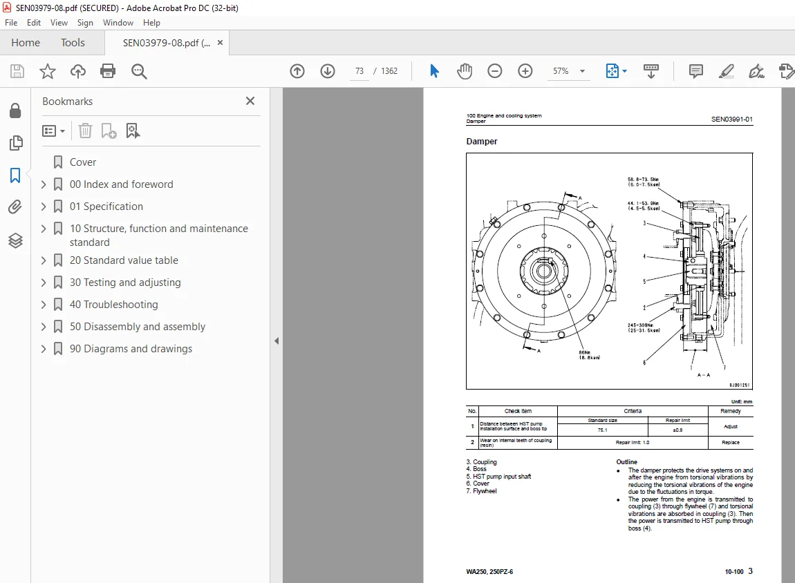
Damper 73
Cooling system 74
Cooling system hydraulic piping diagram 75
Cooling fan motor 77
200 Power train 87
Power train 89
Power train system diagram 90
Drive shaft 92
HST hydraulic piping diagram 93
HST pump 94
HST motor 102
Transfer 108
Clutch solenoid valve 119
Axle 120
Differential 122
Torque proportioning differential 127
Limited slip differential 130
Final drive 134
300 Steering system 141
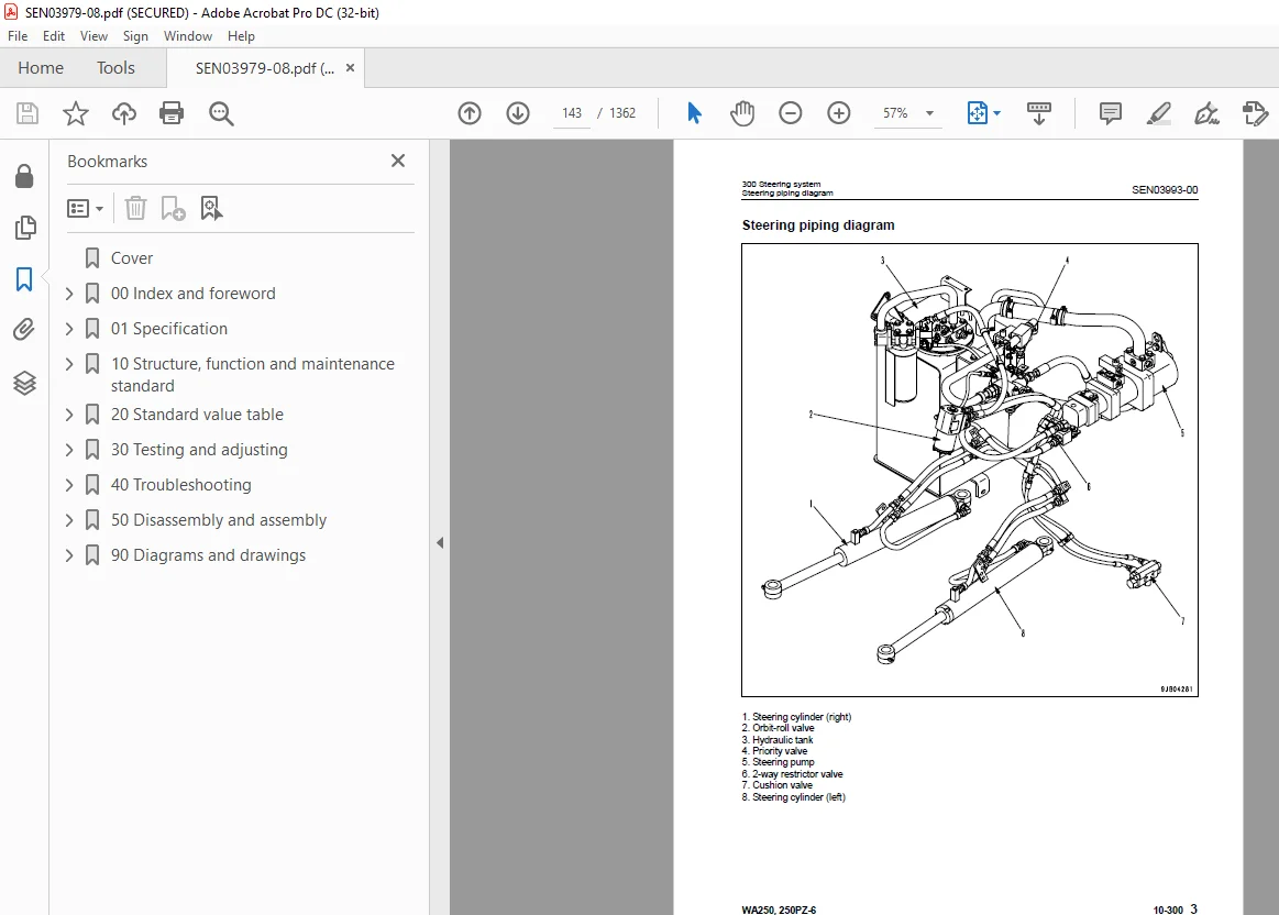
Steering piping diagram 143
Steering column 144
Priority valve 145
Orbit-roll valve 148
2-way restrictor valve 156
Cushion valve 157
Steering cylinder 158
Emergency steering piping diagram 160
Emergency steering valve 161
Steering relief valve 164
400 Brake system 167
Brake piping diagram 169
Charge valve 170
Brake valve 174
Inching valve 178
Accumulator (for brake) 179
Slack adjuster 180
Brake 182
Parking brake control 187
Parking brake 188
500 Undercarriage and frame 191
Axle mount and center hinge pin 192
Tires 197
600 Hydraulic system 199
Work equipment hydraulic piping diagram 200
Work equipment control lever linkage 204
Hydraulic tank 210
4-gear pump 212
Work equipment control valve 214
PPC valve 239
Lock valve 254
Accumulator (for PPC circuit) 255
Bypass valve 256
Quick coupler solenoid valve 259
ECSS valve 260
Accumulator (for ECSS) 262
700 Work equipment 265
Work equipment linkage 266
Bucket 270
Bucket positioner and boom kick-out 274
Work equipment cylinder 286
800 Cab and its attachments 289
Cab 291
Air conditioner 292
910 Electrical system, Part 1 305
Machine monitor system 306
Machine monitor 310
Rearview monitor system 331
920 Electrical system, Part 2 337
Electrical system (HST controller system) 338
HST controller 354
ECSS system 356
KOMTRAX system 358
Engine starting circuit 360
Engine stopping circuit 362
Preheating circuit 363
Engine output derating function 364
Automatic warm-up function 364
Parking brake circuit 365
Coupler plunger control system 368
Max traction switch 369
Multi-function knob 370
Sensor 371
20 Standard value table 379
100 Standard service value table 379
Standard service value table for engine 380
Standard service value table for chassis 381
30 Testing and adjusting 389
110 Testing and adjusting, Part 1 389
Precautions before work 391
Tools for testing, adjusting, and troubleshooting 392
Sketches of special tools 397
Measuring engine speed 398
Measuring exhaust gas color 400
Adjusting valve clearance 402
Measuring compression pressure 404
Measuring blow-by pressure 407
Measuring engine oil pressure 408
Measuring intake air (boost) pressure 409
Handling fuel system equipment 411
Releasing residual pressure in fuel system 411
Measuring fuel pressure 412
Measuring fuel return rate and leakage 414
Bleeding air from fuel circuit 418
Checking leakage in fuel system 419
Handling cylinder cut-out mode operation 420
Handling no-injection cranking operation 420
Handling controller voltage circuit 421
Check of muffler and muffler stack for looseness and damage 421
Check of muffler function 422
Check of installed condition of cylinder head and manifolds 422
Check of engine piping for damage and looseness 423
Testing and adjusting air conditioner compressor belt tension 423
Replacing alternator belt 424
120 Testing and adjusting, Part 2 427
Checking operating force of accelerator pedal 429
Checking directional lever 430
Testing and adjusting HST oil pressure 431
Testing clutch control pressure 435
Testing and adjusting steering wheel 436
Testing and adjusting steering oil pressure 438
Bleeding air from steering circuit 440
Testing hydraulic fan 441
Measuring brake pedal 443
Testing and adjusting brake pedal linkage 444
Measuring brake performance 445
Testing and adjusting accumulator charge pressure 446
Testing wheel brake oil pressure 448
Testing wear of brake disc 451
Bleeding air from wheel brake circuit 452
Releasing residual pressure in brake accumulator circuit 453
Testing parking brake performance 454
Testing and adjusting parking brake control cable 455
Measuring and adjusting work equipment control lever 456
Testing and adjusting work equipment hydraulic pressure 457
Testing work equipment PPC oil pressure 458
Bleeding air from hydraulic circuit 460
Releasing remaining pressure in hydraulic circuit 461
Testing and adjusting bucket positioner 462
Testing and adjusting of boom kick-out switch 463
Checking proximity switch operation pilot lamp 464
Procedure for testing diodes 465
Preparation work for troubleshooting for electric system 467
Starting KOMTRAX terminal operations 471
Indicator lamps of KOMTRAX terminal 475
Adjustment of rearview camera angle 478
130 Testing and adjusting, Part 3 481
Adjusting machine monitor 482
Adjusting replaced, reassembled or added sensor, controller, etc with machine monitor 483
Special functions of machine monitor (EMMS) 485
Pm clinic inspection chart 538
40 Troubleshooting 541
100 Failure code table and fuse locations 541
Precautions before work 542
Failure codes table 543
Fuse locations 549
200 General information on troubleshooting 555
Points to remember when troubleshooting 556
Sequence of events in troubleshooting 557
Testing before troubleshooting 558
Classification and procedures of troubleshooting 559
Information contained in troubleshooting table 562
Connection table for connector pin numbers 564
T- branch box and T- branch adapter table 600
310 Troubleshooting by failure code (Display of code), Part 1 605
Failure code [2G40GZ] Brake: Oil pressure reduction 606
Failure code [6091NX] HST filter: Clogging 608
Failure code [989FN1] Travel speed: Overrun alarm 609
Failure code [AB00L6] Alternator R system: Hot short 610
Failure code [AB00MA] Alternator R system: Ground fault/Disconnection charge/Low charge voltage 612
Failure code [B@BAZG] Engine: Oil pressure reduction 614
Failure code [B@BCNS] Engine: Overheat 615
Failure code [B@BCZK] Engine: Low coolant level 616
Failure code [B@C6NS] Front brake: High oil temperature 618
Failure code [B@CRNS] HST: High oil temperature 619
320 Troubleshooting by failure code (Display of code), Part 2 621
Failure code [CA111] Abnormality in engine controller 623
Failure code [CA115] Engine Ne or Bkup speed sensor error 624
Failure code [CA122] Charge pressure sensor high error 626
Failure code [CA123] Charge pressure sensor low error 628
Failure code [CA131] Throttle sensor high error 630
Failure code [CA132] Throttle sensor low error 632
Failure code [CA144] Coolant sensor high error 634
Failure code [CA145] Coolant sensor low error 636
Failure code [CA153] Charge temperature sensor high error 638
Failure code [CA154] Charge temperature sensor low error 640
Failure code [CA155] Derating of speed by abnormally high charge temperature 642
Failure code [CA187] Sensor power supply 2 low error 644
Failure code [CA221] Atmospheric pressure sensor high error 646
Failure code [CA222] Atmospheric sensor low error 648
Failure code [CA227] Sensor power supply 2 high error 650
Failure code [CA234] Engine overspeed 651
Failure code [CA238] Ne speed sensor power supply error 652
Failure code [CA271] IMV (IMA) Short circuit 653
Failure code [CA272] IMV (IMA) Disconnection 654
Failure code [CA322] Injector #1 open/short error 656
Failure code [CA323] Injector #5 open/short error 658
Failure code [CA324] Injector #3 open/short error 660
Failure code [CA325] Injector #6 open/short error 662
Failure code [CA331] Injector #2 open/short error 664
Failure code [CA332] Injector #4 open/short error 666
Failure code [CA342] Calibration code inconsistency 668
Failure code [CA351] Injectors drive circuit error 670
Failure code [CA352] Sensor power supply 1 low error 672
Failure code [CA386] Sensor power supply 1 high error 674
330 Troubleshooting by failure code (Display of code), Part 3 677
Failure code [CA428] Abnormally high level in water sensor 680
Failure code [CA429] Abnormally low level in water sensor 682
Failure code [CA431] Idle validation switch error 684
Failure code [CA432] Idle validation action error 688
Failure code [CA435] Engine oil pressure switch error 692
Failure code [CA441] Battery voltage low error 693
Failure code [CA442] Battery voltage high error 696
Failure code [CA449] Common rail pressure high error 2 698
Failure code [CA451] Common rail pressure sensor high error 700
Failure code [CA452] Common rail pressure sensor low error 702
Failure code [CA488] Derating of torque by abnormally high charge temperature 704
Failure code [CA553] Common rail pressure high error 1 705
Failure code [CA559] Supply pump pressure very low error 706
Failure code [CA689] Engine Ne speed sensor error 708
Failure code [CA731] Engine Bkup speed sensor phase error 710
Failure code [CA757] All continuous data lost error 711
Failure code [CA778] Engine Bkup speed sensor error 714
Failure code [CA1633] KOMNET datalink timeout error 716
Failure code [CA2185] Throttle sensor supply voltage high error 720
Failure code [CA2186] Throttle sensor power supply low error 722
Failure code [CA2249] Supply pump pressure very low error 2 724
Failure code [CA2311] Abnormality in IMV (IMA) solenoid 726
Failure code [CA2555] Intake heater relay disconnection error 728
Failure code [CA2556] Intake heater relay short circuit error 730
340 Troubleshooting by failure code (Display of code), Part 4 733
Failure code [D160KY] Backup alarm/lamp relay 1 circuit: Hot short 734
Failure code [D192KY] ECSS solenoid relay: Hot short 736
Failure code [D1B0KA] HST safety relay: Disconnection 738
Failure code [D1B0KB] HST safety relay: Ground fault 740
Failure code [D1B0KY] HST safety relay: Hot short 742
Failure code [D5ZHL6] IGN C system: Ground fault/Disconnection 744
Failure code [DAF3KK] UNSW power supply: Ground fault/Disconnection 746
Failure code [DAFRKR] Machine monitor CAN-NET Signal: Disconnection 748
Failure code [DAJ0KK] HST controller power supply: Low voltage 752
Failure code [DAJ0KT] HST controller memory (EEPROM): Abnormality 754
Failure code [DAJ1L4] HST controller main power line: Disconnection/Ground fault 756
Failure code [DAJ1L6] HST controller main power line: Hot short 758
Failure code [DAJ2KK] Controller solenoid power supply: Low voltage 760
Failure code [DAJ2L3] HST controller load power supply holding line: Hot short in wiring harness 762
Failure code [DAJ2L4] HST controller load power supply holding line: Disconnection/Ground fault 764
Failure code [DAJ5KX] Sensor 5V power supply: Out of output range 766
Failure code [DAJ9KQ] HST controller model selection: Disagreement of model selection signals 768
Failure code [DAJRKR] HST controller CAN-NET signal: Disconnection 769
Failure code [DAJRMA] HST controller: Disagreement in option selection 775
350 Troubleshooting by failure code (Display of code), Part 5 777
Failure code [DB2RKR] Engine controller CAN-NET: Disconnection in signal line 778
Failure code [DD1NL4] Fan automatic reverse switch signal: Abnormality 784
Failure code [DD1NLD] Fan reverse switch signal: Abnormality 786
Failure code [DDB6KA] Parking brake reminder signal: Disconnection/Hot short 788
Failure code [DDB6KB] Parking brake indicator signal: Ground fault 790
Failure code [DDB6KZ] Parking brake switch (bottom switch) or parking brake reminder switch (intermediate switch): Trouble 792
Failure code [DDB6L0] Parking brake reminder signal: Ground fault 794
Failure code [DDB6L4] Parking brake indicator signal: Disconnection/Hot short 796
Failure code [DDD7KX] Travel speed control dial signal: Disconnection/Ground fault 798
Failure code [DDD7KY] Travel speed control dial signal: Hot short 800
Failure code [DDE5MA] Emergency steering operation switch: Disconnection 802
Failure code [DDK3KA] Directional selector switch: Disconnection/Hot short 804
Failure code [DDK3KB] Directional selector switch: Ground fault 806
Failure code [DDK6KA] FNR lever: Disconnection/Ground fault 808
Failure code [DDK6KY] FNR lever: Hot short 812
Failure code [DDS5L6] Steering: Low oil pressure (Operation of emergency steering) 814
360 Troubleshooting by failure code (Display of code), Part 6 817
Failure code [DF10KA] Travel speed range selector switch: Disconnection/Ground fault 818
Failure code [DF10KB] Travel speed range selector switch: Hot short 822
Failure code [DGH1KX] HST oil temperature sensor: Ground fault 824
Failure code [DGR2KB] Brake oil temperature sensor: Ground fault 825
Failure code [DGR2KZ] Brake oil temperature sensor: Disconnection/Hot short 826
Failure code [DHH1KX] HST oil pressure sensor: Disconnection/Ground fault 828
Failure code [DHH1KY] HST oil pressure sensor: Hot short 830
Failure code [DHTCL6] HST filter clogging sensor: Functional defect 832
Failure code [DJF1KA] Fuel level sensor: Disconnection/Hot short 834
Failure code [DLT3KX] Travel speed sensor B: Abnormality 836
Failure code [DLT4KX] Travel speed sensor A: Abnormality 840
Failure code [DLT4LC] Travel speed sensor A & B: Abnormality 842
Failure code [DV00KY] Alarm buzzer: Hot short 844
Failure code [DW26KA] Motor 2 solenoid: Disconnection/Ground fault 846
Failure code [DW26KY] Motor 2 solenoid: Hot short 848
Failure code [DW7BKY] Fan reverse solenoid circuit: Hot short 850
Failure code [DW7BKZ] Fan reverse solenoid circuit: Disconnection/Ground fault 852
370 Troubleshooting by failure code (Display of code), Part 7 855
Failure code [DX16KA] Fan EPC solenoid: Disconnection 856
Failure code [DX16KB] Fan EPC solenoid: Ground fault 857
Failure code [DX16KY] Fan EPC solenoid: Hot short 858
Failure code [DX19KA] Motor 1 solenoid: Disconnection 860
Failure code [DX19KB] Motor 1 solenoid: Ground fault 862
Failure code [DX19KY] Motor 1 solenoid: Hot short 864
Failure code [DX20KA] Clutch EPC solenoid: Disconnection 866
Failure code [DX20KB] Clutch EPC solenoid: Ground fault 868
Failure code [DX20KY] Clutch EPC solenoid: Hot short 870
Failure code [DXH7KB] Reverse solenoid: Ground fault 872
Failure code [DXH7KZ] Reverse solenoid: Disconnection/Hot short 874
Failure code [DXH8KB] Forward solenoid: Ground fault 876
Failure code [DXH8KZ] Forward solenoid: Disconnection/Hot short 878
Failure code [J141N1] Steering pump: Overrun alarm 880
Failure code [M100N1] HST pump: Overrun alarm 880
Failure code [M400N1] Motor 1: Overrun alarm 881
400 Troubleshooting of electrical system (E-mode) 883
E-1 Engine does not start 886
E-2 Preheater does not operate normally 894
E-3 Travel speed is low or high 898
E-4 ECSS does not operate 904
E-5 ECSS keeps operating 907
E-6 Defective boom kick-out function and cancellation 910
E-7 Defective bucket positioner function and cancellation 914
E-8 Defective lift arm FLOATING holding function and cancellation 918
E-9 Travel direction selection system does not function 922
E-10 Fan does not reverse 926
E-11 Fan keeps rotating in reverse 930
E-12 Wiper does not operate 932
E-13 Windshield washer does not operate 936
E-14 Headlamp, clearance lamp and tail lamp do not light up or go off 940
E-15 Working lamp does not light up or go off 948
E-16 Turn signal lamp and hazard lamp do not light up or go off 953
E-17 Brake lamp does not light or it keeps lighting up 960
E-18 Backup lamp does not light or it keeps lighting up 962
E-19 Backup alarm does not sound or it keeps sounding 965
E-20 Horn does not sound or it keeps sounding 968
E-21 Alarm buzzer does not sound or it keeps sounding 970
E-22 Air conditioner does not operate or stop 972
E-23 The KOMTRAX system does not work properly 975
E-24 Rearview monitor does not light up or backlight flickers 978
E-25 Rearview monitor images are not displayed clearly 982
E-26 Rearview monitor brightness cannot be adjusted 986
E-27 Night lighting lamp of rearview monitor is abnormal 990
E-28 Reverse interlock function of rearview monitor does not operate properly 993
500 Troubleshooting of hydraulic and mechanical system (H-mode) 997
Method of using troubleshooting chart 999
Failure code and cause table1002
H-1 The machine does not start1004
H-2 The travel speed is slow1005
H-3 The traction force is weak1006
H-4 Engine stalls when traveling or engine speed drops excessively1007
H-5 The gear is not shifted1008
H-6 The steering wheel does not turn1009
H-7 The steering wheel is heavy1010
H-8 Steering wheel shakes or jerks1011
H-9 Machine deviates naturally to one side when traveling1011
H-10 The brake does not work or does not work well1012
H-11 The brake is not released or is dragged1013
H-12 The lift arm does not rise or lower1014
H-13 The lift arm moves slowly or the lift arm rising force is insufficient1015
H-14 When rising, the lift arm comes to move slowly at specific height1016
H-15 The lift arm cylinder cannot hold down the bucket (The bucket rises in the air)1016
H-16 Hydraulic drifts of the lift arm occur often1016
H-17 The lift arm wobbles during operation1016
H-18 When the control lever is switched from “HOLD” to “RAISE,” the lift arm falls temporarily1017
H-19 The bucket does not tilt back1018
H-20 The bucket moves slowly or the tilting-back force is insufficient1019
H-21 The bucket comes to operate slowly in the midst of tilting-back1020
H-22 The bucket cylinder cannot hold down the bucket1020
H-23 Hydraulic drifts of the bucket occur often1020
H-24 The bucket wobbles during travel with load (The work equipment valve is set to “HOLD”)1020
H-25 When the control lever is switched from “HOLD” to “TILT,” the bucket falls temporarily1021
H-26 The control levers of the lift arm and bucket do not move smoothly and heavy1021
H-27 The ECSS does not operate and machine pitches and bounces1022
H-28 Fan revolution is abnormal (Fan sound/vibration is abnormally large or engine overheats)1023
600 Troubleshooting of engine (S-mode)1025
Method of using troubleshooting charts1026
S-1 Starting performance is poor1030
S-2 Engine does not start1031
S-3 Engine does not pick up smoothly1034
S-4 Engine stops during operations1035
S-5 Engine does not rotate smoothly1036
S-6 Engine lacks output (or lacks power)1037
S-7 Exhaust smoke is black (incomplete combustion)1038
S-8 Oil consumption is excessive (or exhaust smoke is blue)1039
S-9 Oil becomes contaminated quickly1040
S-10 Fuel consumption is excessive1041
S-11 Oil is in coolant (or coolant spurts back or coolant level goes down)1042
S-12 Oil pressure drops1043
S-13 Oil level rises (Entry of coolant or fuel)1044
S-14 Coolant temperature becomes too high (overheating)1045
S-15 Abnormal noise is made1046
S-16 Vibration is excessive1047
50 Disassembly and assembly1049
100 General information on disassembly and assembly1049
Precautions before work1050
How to read this manual1051
Coating materials list1053
Special tools list1056
Sketches of special tools1060
200 Engine and cooling system1071
Removal and installation of fuel supply pump assembly1072
Removal and installation of fuel injector assembly1074
Removal and installation of cylinder head assembly1082
Removal and installation of engine hood assembly1095
Removal and installation of radiator1098
Removal and installation of air aftercooler1101
Removal and installation of hydraulic oil cooler assembly1103
Removal and installation of engine assembly1105
Removal and installation of engine front oil seal assembly1111
Removal and installation of engine rear oil seal assembly1114
Removal and installation of cooling fan and fan motor assembly1117
Removal and installation of fuel tank assembly1120
310 Power train, Part 11123
Removal and installation of transfer assembly1124
Disassembly and assembly of transfer assembly1128
Removal and installation of parking brake assembly1148
Disassembly and assembly of parking brake assembly1150
320 Power train, Part 21157
Removal and installation of front axle assembly1158
Removal and installation of rear axle assembly1160
Disassembly and assembly of axle housing assembly1163
Disassembly and assembly of differential assembly1172
400 Undercarriage and frame1201
Removal and installation of center hinge pin1202
Removal and installation of counterweight1212
500 Hydraulic system1215
Removal and installation of HST pump and 4-gear pump assembly1216
Disassembly and assembly of HST pump assembly1220
Removal and installation of HST motor 1 assembly1247
Removal and installation of HST motor 2 assembly1249
Disassembly and assembly of HST motor assembly1251
Removal and installation of work equipment control valve assembly1267
Removal and installation of hydraulic tank1269
Disassembly and assembly of hydraulic cylinder assembly1271
600 Work equipment1279
Removal and installation of work equipment assembly1280
700 Cab and its attachments1289
Removal and installation of operator’s cab and floor frame assembly1290
Removal and installation of operator’s cab glass (Stuck glass)1295
Removal and installation of air conditioner unit1303
800 Electrical system1311
Removal and installation of monitor panel1312
Removal and installation of engine controller assembly1314
Removal and installation of HST controller assembly1315
Removal and installation of KOMTRAX terminal assembly1316
90 Diagrams and drawings1319
100 Hydraulic diagrams and drawings1319
Automatic greasing circuit diagram1320
Hydraulic circuit diagram1323
200 Electrical diagrams and drawings1329
Electrical circuit diagram1331
Connector list and stereogram1359
S.M 29/12/24