
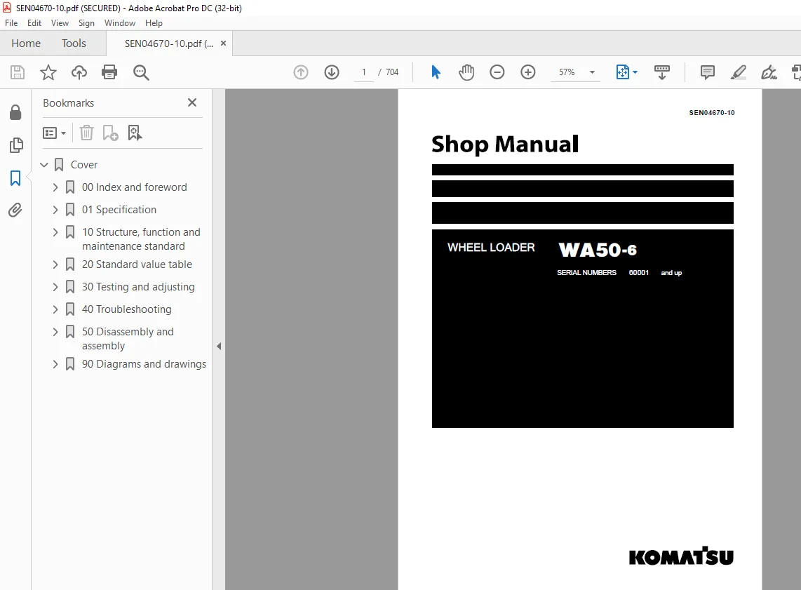
Komatsu Wheel Loader WA50-6 Shop Manual SEN04670-10 – PDF DOWNLOAD
$33.95
Komatsu Wheel Loader WA50-6 Shop Manual SEN04670-10 – PDF DOWNLOAD
SERIAL NUMBERS 60001 and up
Description
Komatsu Wheel Loader WA50-6 Shop Manual SEN04670-10 – PDF DOWNLOAD
FILE DETAILS:
Komatsu Wheel Loader WA50-6 Shop Manual SEN04670-10 – PDF DOWNLOAD
Language : English
Pages :704
Downloadable : Yes
File Type : PDF
DESCRIPTION:
Komatsu Wheel Loader WA50-6 Shop Manual SEN04670-10 – PDF DOWNLOAD
SERIAL NUMBERS 60001 and up
1. General precautions
Mistakes in operation are extremely dangerous. Read the Operation and Maintenance Manual carefully before operating the machine. In addition, read this manual and understand its contents before starting the work.
TABLE OF CONTENTS:
Komatsu Wheel Loader WA50-6 Shop Manual SEN04670-10 – PDF DOWNLOAD
SERIAL NUMBERS 60001 and up
Cover 1
00 Index and foreword 3
100 Index 3
Composition of shop manual 4
Table of contents 6
200 Foreword and general information 13
Safety notice 14
How to read the shop manual 19
Explanation of terms for maintenance standard 21
Handling of electric equipment and hydraulic component 23
Handling of connectors newly used for engines 32
How to read electric wire code 35
Precautions when carrying out operation 38
Method of disassembling and connecting push-pull type coupler 41
Standard tightening torque table 44
Conversion table 48
01 Specification 55
100 Specification and technical data 55
Specification dimension drawing 56
Specifications 57
Weight table 61
Table of fuel, coolant and lubricants 62
10 Structure, function and maintenance standard 65
100 Engine and cooling system 65
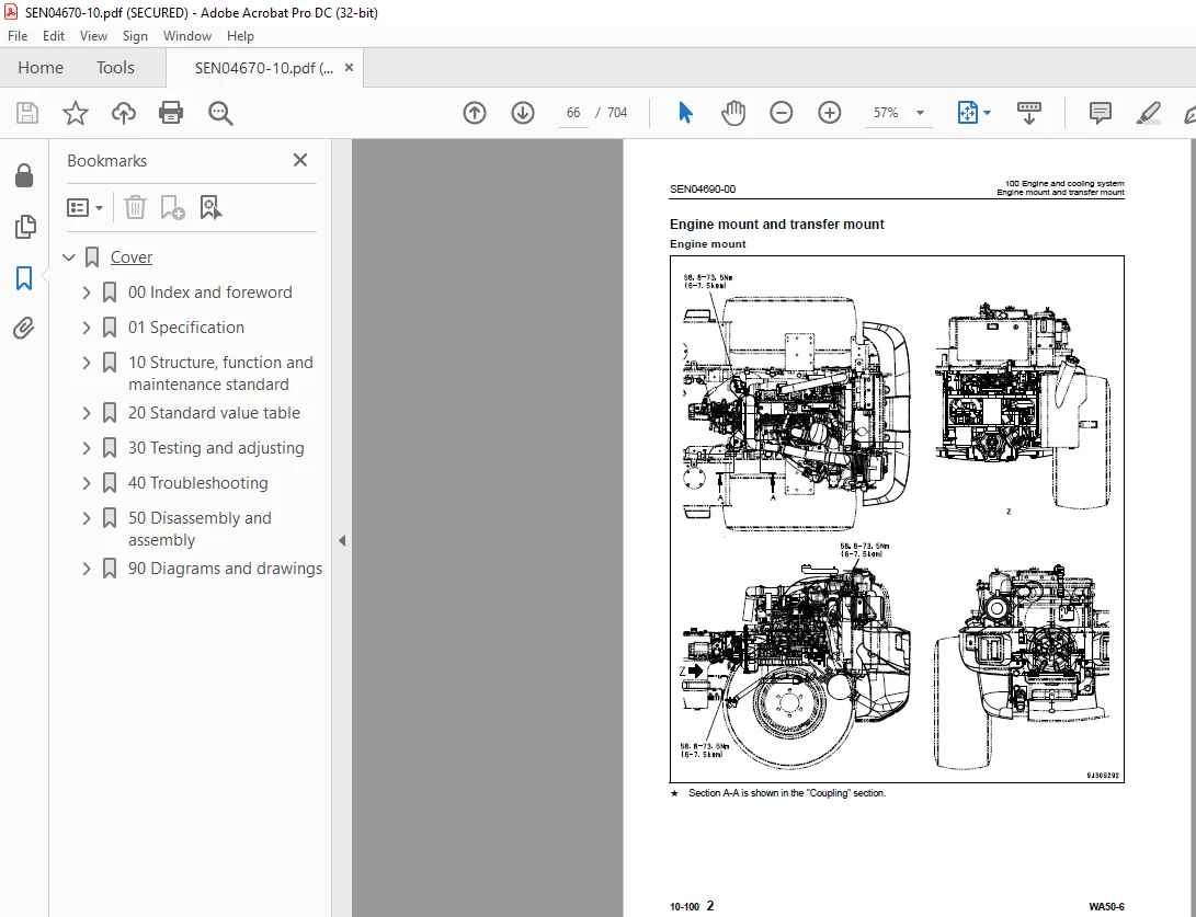
Engine mount and transfer mount 66
Coupling 68
Cooling system 69
Cooling system hydraulic piping diagram 70
200 Power train 73
Power train 75
Power train system diagram 76
Drive shafts 78
HST hydraulic piping diagram 79
HST pump 80
HST motor 90
Transfer100
Axle106
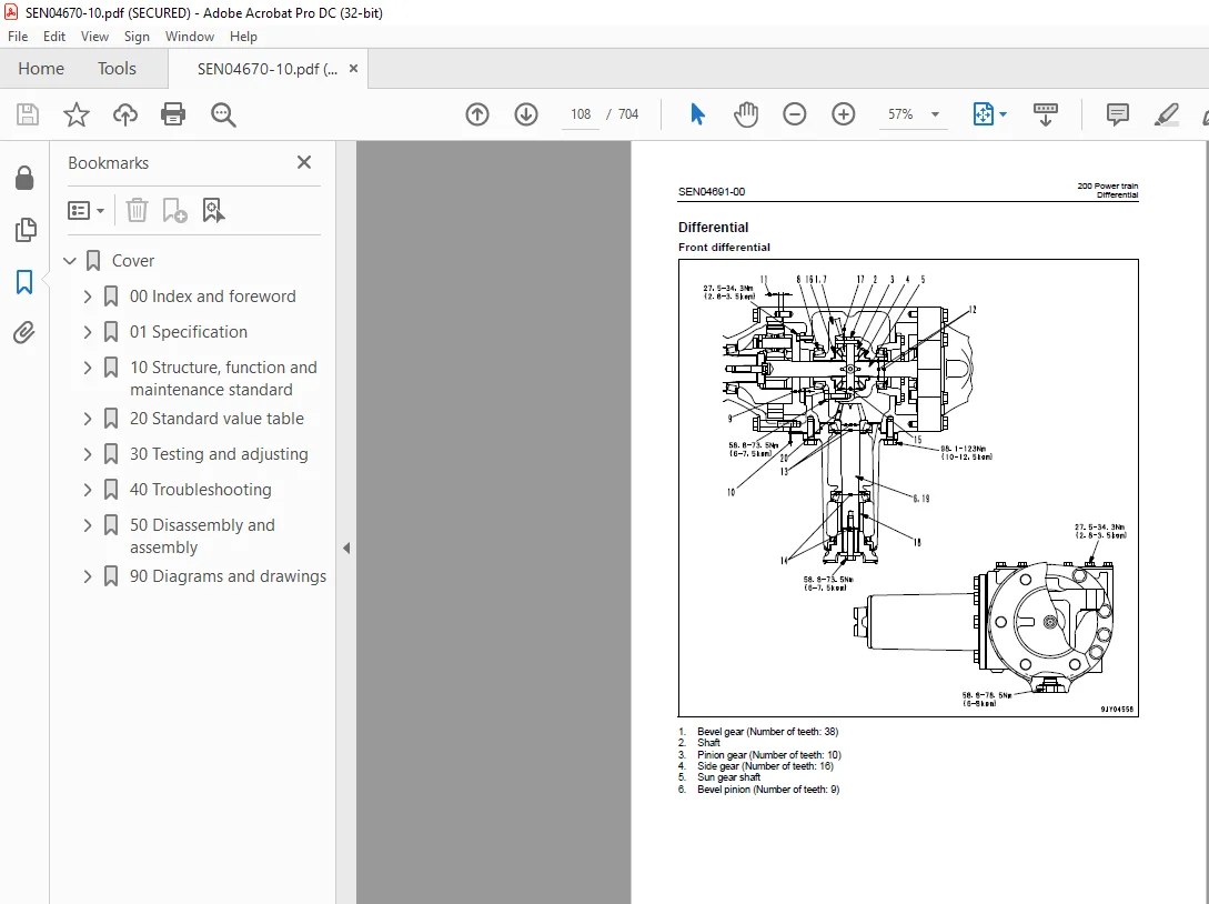
Differential108
Final drive113
300 Steering system119
Steering piping diagram120
Steering column121
Priority valve122
Orbit-roll valve123
Steering cylinder128
400 Brake system131
Brake control132
Brake (also used as parking brake)134
500 Undercarriage and frame137
Axle mount and center hinge pin138
600 Hydraulic system145
Work equipment hydraulic piping diagram146
Work equipment control lever linkage148
Hydraulic tank149
2-unit gear pump151
Work equipment control valve152
700 Work equipment163
Work equipment linkage164
Bucket167
Bucket positioner168
Work equipment cylinder172
800 Cab and its attachments175
Cab176
Air conditioner178
Heater185
Canopy187
910 Electrical system, Part 1189
Machine monitor system190
Machine monitor195
HST electronic control system199
Electrical system (HST controller system)200
HST controller210
920 Electrical system, Part 2213
KOMTRAX system214
Engine start circuit217
Engine stop circuit218
Preheating circuit219
Travel mode selector switch220
Travel speed control dial221
Sensors222
20 Standard value table231
100 Standard service value table231
Standard service value table for engine232
Standard service value table for chassis233
30 Testing and adjusting239
110 Testing and adjusting, Part 1239
Precautions before work240
Tools for testing, adjusting, and troubleshooting241
Testing and adjusting engine speed243
Testing exhaust gas color246
Testing and adjusting valve clearance247
Testing compression pressure249
Testing engine oil pressure250
Testing and adjusting fuel injection timing251
Bleeding air from fuel circuit255
Check of installed condition of cylinder head and manifolds256
Check of engine piping for damage and looseness256
Check of muffler and muffler stack for looseness and damage257
Check of muffler function257
Testing, adjusting and replacing alternator belt258
Testing, adjusting and replacing air conditioner compressor belt259
120 Testing and adjusting, Part 2263
Testing operating force of accelerator pedal265
Testing fuel level sensor267
Testing directional lever268
Testing and adjusting HST oil pressure269
Adjusting travel speed sensor273
Testing and adjusting steering wheel274
Testing and adjusting steering oil pressure276
Bleeding air from steering circuit278
Testing brake pedal279
Testing and adjusting brake pedal and linkage280
Testing and adjusting brake switch281
Testing brake performance282
Testing brake disc wear283
Testing and adjusting inching potentiometer linkage284
Testing and adjusting parking brake control linkage285
Measuring parking brake performance287
Testing and adjusting work equipment control lever288
Testing and adjusting work equipment hydraulic pressure290
Testing travel of main control valve spool291
Bleeding air from hydraulic circuit292
Releasing remaining pressure in hydraulic circuit293
Testing and adjusting bucket positioner294
Checking proximity switch operation pilot lamp295
Procedure for testing diodes296
Preparation work for troubleshooting for electrical system298
How to start operation of KOMTRAX terminal300
Lamp display of KOMTRAX terminal304
Removal and installation of KOMTRAX terminal307
Pm clinic inspection chart308
Pm clinic inspection chart309
40 Troubleshooting311
100 Failure code table and fuse locations311
Precautions before work312
Failure codes table313
How to select failure code display and how to read failure code314
Fuse locations317
200 General information on troubleshooting321
Points to remember when troubleshooting322
Sequence of events in troubleshooting323
Testing before troubleshooting324
Classification and procedures of troubleshooting325
Information contained in troubleshooting table328
Connection table for connector pin numbers330
T- branch box and T- branch adapter table366
300 Troubleshooting by failure code (Display of code)371
Failure code [12] Directional (FNR) lever: Disconnection, ground fault, hot short372
Failure code [13] Engine speed sensor: Disconnection, hot short376
Failure code [14] Travel speed sensor: Disconnection, ground fault, hot short, defective installation378
Failure code [22] MB (forward) pressure sensor: Disconnection, ground fault, hot short380
Failure code [23] MA (reverse) pressure sensor: Disconnection, ground fault, hot short382
Failure code [24] Travel speed variable potentiometer: Disconnection, ground fault, hot short384
Failure code [25] Inching pedal potentiometer: Disconnection, ground fault, hot short386
Failure code [26] HST oil temperature sensor: Ground fault388
Failure code [32] HST pump forward EPC: Disconnection, short circuit, ground fault, hot short390
Failure code [33] HST pump reverse EPC: Disconnection, short circuit, ground fault, hot short392
Failure code [34] HST motor EPC: Disconnection, short circuit, ground fault, hot short394
Failure code [36] HST pump forward EPC/reverse EPC: Sticking (foreign matter in system etc)396
Failure code [42] HST oil temperature: Overheat397
Failure code [52] Source voltage: Voltage drop, disconnection398
Failure code [53] Solenoid power supply: Voltage drop, disconnection400
Failure code [54] ACC signal: Disconnection, ground fault402
Failure code [55] Potentiometer power supply: Ground fault, hot short404
400 Troubleshooting of electrical system (E-mode)407
E-1 Engine does not start408
E-2 Engine does not stop416
E-3 Preheater does not operate normally418
E-4 Travel speed is low or high420
E-5 Parking brake omission alarm malfunctions422
E-6 Bucket positioner does not function or cannot be reset424
E-7 Travel direction cannot be changed normally426
E-8 Windshield wiper does not operate428
E-9 Window washer does not operate432
E-10 Headlamp, clearance lamp, tail lamp and license lamp do not light or go off436
E-11 Working lamp and rotary lamp do not light or go off442
E-12 Turn signal lamp does not light or go off448
E-13 Stop lamp does not light or go off452
E-14 Backup lamp does not light or go off454
E-15 Backup buzzer does not sound or stop sounding456
E-16 Horn does not sound or stop sounding460
E-17 Alarm buzzer does not sound or stop sounding462
E-18 Fuel level is not displayed normally464
E-19 Air conditioner does not work466
E-20 KOMTRAX system does not operate normally476
500 Troubleshooting of hydraulic and mechanical system (H-mode)481
Method of using troubleshooting chart483
Failure phenomenon and cause table486
H-1 The machine does not start488
H-2 The travel speed is slow489
H-3 The traction force is weak490
H-4 Engine stalls when traveling or engine speed drops excessively491
H-5 Travel speed variable dial does not function492
H-6 The steering wheel does not turn493
H-7 The steering wheel is heavy494
H-8 Steering wheel shakes or jerks495
H-9 Machine deviates naturally to one side when traveling495
H-10 The brake does not work or does not work well496
H-11 The brake is not released or is dragged497
H-12 Parking brake does not work at all or sufficiently498
H-13 Parking brake is not reset or it drags499
H-14 The lift arm does not rise or lower500
H-15 The lift arm moves slowly or the lift arm rising force is insufficient501
H-16 When rising, the lift arm comes to move slowly at specific height502
H-17 The lift arm cylinder cannot hold down the bucket (The bucket rises in the air)502
H-18 Hydraulic drifts of the lift arm occur often502
H-19 The lift arm wobbles during operation502
H-20 When the control lever is switched from “HOLD” to “RAISE,” the lift arm falls temporarily503
H-21 The bucket does not tilt back504
H-22 The bucket moves slowly or the tilting-back force is insufficient505
H-23 The bucket comes to operate slowly in the midst of tilting-back506
H-24 The bucket cylinder cannot hold down the bucket506
H-25 Hydraulic drifts of the bucket occur often506
H-26 The bucket wobbles during travel with load (The work equipment valve is set to “HOLD”)506
H-27 When the control lever is switched from “HOLD” to “TILT,” the bucket falls temporarily507
H-28 The control levers of the lift arm and bucket do not move smoothly and heavy507
600 Troubleshooting of engine (S-mode)509
Method of using troubleshooting charts511
S-1 Starting performance is poor514
S-2 Engine does not start515
S-3 Engine does not pick up smoothly518
S-4 Engine stops during operations519
S-5 Engine does not rotate smoothly520
S-6 Engine lacks output (or lacks power)521
S-7 Exhaust smoke is black (incomplete combustion)522
S-8 Oil consumption is excessive (or exhaust smoke is blue)523
S-9 Oil becomes contaminated quickly524
S-10 Fuel consumption is excessive525
S-11 Oil is in coolant (or coolant spurts back or coolant level goes down)526
S-12 Oil pressure drops527
S-13 Oil level rises (Entry of coolant/fuel)528
S-14 Coolant temperature becomes too high (overheating)529
S-15 Abnormal noise is made530
S-16 Vibration is excessive531
50 Disassembly and assembly533
100 General information on disassembly and assembly533
Precautions before work534
How to read this manual535
Coating materials list537
Special tools list540
200 Engine and cooling system545
Removal and installation of fuel injection pump assembly546
Removal and installation of nozzle holder assembly551
Removal and installation of cylinder head assembly553
Removal and installation of radiator assembly557
Removal and installation of engine hood assembly558
Removal and installation of hydraulic oil cooler assembly559
Removal and installation of radiator and hydraulic oil cooler assembly561
Removal and installation of engine and HST pump assembly564
Removal and installation of engine front oil seal assembly568
Removal and installation of engine rear oil seal assembly570
Removal and installation of fuel tank assembly571
300 Power train575
Removal and installation of transfer assembly576
Disassembly and assembly of transfer assembly578
Removal and installation of parking brake assembly584
Disassembly and assembly of parking brake assembly586
Removal and installation of front axle assembly589
Removal and installation of rear axle assembly590
Disassembly and assembly of axle housing assembly592
Disassembly and assembly of differential assembly601
400 Undercarriage and frame613
Removal and installation of center hinge pin614
Removal and installation of counterweight assembly628
500 Hydraulic system631
Removal and installation of HST pump assembly632
Removal and installation of HST motor assembly634
Removal and installation of work equipment control valve assembly636
Removal and installation of hydraulic tank assembly637
Disassembly and assembly of hydraulic cylinder assembly640
600 Work equipment645
Removal and installation of work equipment assembly646
700 Cab and its attachments651
Removal and installation of canopy assembly652
Removal and installation of operator’s cab assembly653
Removal and installation of operator’s cab glass (Stuck glass)658
Removal and installation of floor frame assembly666
Removal and installation of heater unit assembly671
Removal and installation of air conditioner unit assembly673
Removal and installation of air conditioner condenser assembly675
Removal and installation of air conditioner compressor assembly677
800 Electrical system681
Removal and installation of front monitor panel assembly682
Removal and installation of right side monitor panel assembly684
Removal and installation of HST controller assembly685
Removal and installation of KOMTRAX terminal assembly687
90 Diagrams and drawings689
100 Hydraulic diagrams and drawings689
Hydraulic circuit diagram691
200 Electrical diagrams and drawings695
Electrical circuit diagram697
Connector list and stereogram701
IMAGES PREVIEW OF THE MANUAL:
S.M 26/12/24



