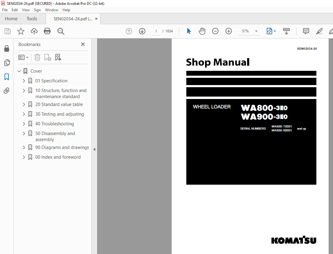
Komatsu WHEEL LOADER WA800-3E0 WA900-3E0 Shop Manual SEN02034-26 PDF
$33.95
Komatsu WHEEL LOADER WA800-3E0 WA900-3E0 Shop Manual SEN02034-26 – PDF DOWNLOAD
SERIAL NUMBERS WA800-70001
WA900-60001 and up
Description
Komatsu WHEEL LOADER WA800-3E0 WA900-3E0 Shop Manual SEN02034-26 – PDF DOWNLOAD
FILE DETAILS:
Komatsu WHEEL LOADER WA800-3E0 WA900-3E0 Shop Manual SEN02034-26 – PDF DOWNLOAD
Language : English
Pages :1634
Downloadable : Yes
File Type : PDF
DESCRIPTION:
Komatsu WHEEL LOADER WA800-3E0 WA900-3E0 Shop Manual SEN02034-26 – PDF DOWNLOAD
SERIAL NUMBERS WA800-70001
WA900-60001 and up
1. General precautions
Mistakes in operation are extremely dangerous. Read the Operation and Maintenance Manual carefully before operating the machine. In addition, read this manual and understand its contents before starting the work.
TABLE OF CONTENTS:
Komatsu WHEEL LOADER WA800-3E0 WA900-3E0 Shop Manual SEN02034-26 – PDF DOWNLOAD
SERIAL NUMBERS WA800-70001
WA900-60001 and up
Cover 1
01 Specification 63
Specification and technical data 63
General assembly drawing 64
Specifications 66
Weight table 69
Table of fuel, coolant and lubricants 72
10 Structure, function and maintenance standard 75
Engine and cooling system 75
Engine mount 76
Transmission mount 77
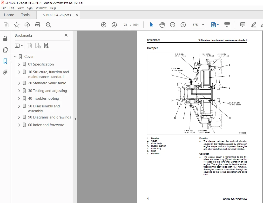
Damper 78
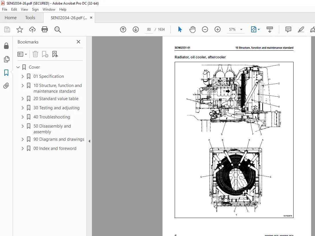
Radiator, oil cooler, aftercooler 80
Fuel system 83
Power train, Part 1 85
Power train 86
Power train system 88
Torque converter 90
Torque converter regulator valve 98
Transmission 100
Transfer 112
Transmission control valve 115
Power train, Part 2 133
Torque converter oil cooler 134
Drive shaft 136
Center support 138
Axle 140
Differential 142
Final drive 148
Steering system 153
Steering piping 154
AJSS lever linkage 156
EPC valve 157
Steering column 158
Rotary valve 159
Steering control valve 162
Steering unit (orbit-roll valve) 174
Steering pump 177
Steering cylinder 179
Slow return valve 181
Emergency steering piping 182
Diverter valve 183
Emergency steering pump 189
Brake system 191
Brake piping 192
Brake 193
Brake valve 196
Accumulator charge valve 204
PPC relief valve 208
Accumulator (for brake) 210
Slack adjuster 211
Parking brake 213
Parking brake caliper 215
Spring cylinder 216
Parking brake solenoid 217
Brake cooling system (if equipped) 218
Brake cooling system (55°C specification) (If equipped) 228
Undercarriage and frame 237
Axle mount 238
Center hinge pin 241
Tire and wheel 243
Jack up point 244
Hydraulic system, Part 1 247
Hydraulic piping 248
Work equipment lever linkage 249
Hydraulic tank 250
Torque conbverter charging, PPC and brake pump 254
Hydraulic system, Part 2 257
Main control valve 258
Accumulator (For PPC valve) 273
Main piston pump 274
Main piston pump cut-off solenoid valve 285
PPC valve 286
PPC relief valve 291
Switch pump 292
Control pump 301
Work equipment 305
Work equipment linkage 306
Bucket positioner and lift arm kick-out 310
Remote lift arm positioner 312
Auto greasing system 313
Hydraulic cylinder 314
Cab and its attachments 317
ROPS cab 318
Air conditioner 319
Electrical system, Part 1 323
Machine monitor system 324
Main monitor 326
Maintenance monitor 330
Electrical system, Part 2 371
Work equipment control system 372
Remote position, joystick steering controller 375
Active power maximizing electrical circuit 376
Automatic transmission system (ATM) 383
Electrical system, Part 3 405
Engine starting/stopping circuit 406
Parking brake circuit 408
Preheating circuit 414
Emergency engine stop 416
Hydraulic oil level sensor 418
Battery and starting motor disconnector switch and starting aid connector 420
Sensor 422
20 Standard value table 447
Standard service value table 447
Standard value table for engine 448
Standard value table for chassis 449
Standard value table for electrical system 454
30 Testing and adjusting 471
Testing and adjusting, Part 1 471
Precautions before work 473
Tools for testing, adjusting, and troubleshooting 474
Measuring engine speed 479
Measuring intake air (boost) pressure 481
Measuring exhaust gas color 482
Measuring exhaust temperature 483
Adjusting valve clearance 485
Measuring compression pressure 486
Measuring blow-by pressure 488
Measuring engine oil pressure 490
Handling fuel system equipment 491
Releasing residual pressure in fuel system 491
Testing fuel pressure 492
Measuring fuel return rate and leakage 493
Bleeding air from fuel circuit 496
Testing leakage in fuel system 498
Handling reduced cylinder mode operation 499
Handling no-injection cranking operation 499
Handling controller voltage circuit 500
Adjusting speed sensor 500
Testing and adjusting alternator belt tension 501
Testing and adjusting belt tension for air conditioner compressor 502
Testing of upper drive shaft sliding part 503
Testing and adjusting power train oil pressure 504
Procedure for operating emergency steering spool when transmission valve fails 509
Testing and adjusting, Part 2 513
Measuring operating effort of AJSS lever (AJSS specification) 515
Testing and adjusting AJSS lever angle sensor and frame angle sensor (AJSS specification) 516
Testing and adjusting steering stopper bolt (AJSS specification) 518
Testing and adjusting steering stop valve 520
Measuring steering oil pressure 521
Testing and adjusting emergency steering oil pressure 522
Bleeding air from steering circuit 524
Measuring brake pedal 525
Measuring brake performance 526
Testing and adjusting accumulator charge pressure 527
Testing of accumulator nitrogen gas pressure and procedure for charging accumulator with nitrogen gas 529
Measuring wheel brake oil pressure reduction 537
Measuring wear of wheel brake disc 539
Bleeding air from wheel brake circuit 540
Releasing residual pressure in brake accumulator circuit 541
Testing parking brake performance 542
Measuring parking brake solenoid oil pressure 543
Testing and adjusting wear of parking brake pad 544
Testing and adjusting PPC oil pressure 545
Adjusting PPC valve linkage 547
Testing and adjusting work equipment oil pressure 548
Bleeding air from piston pump 550
Bleeding air from work equipment circuit 551
Adjusting work equipment lever linkage 552
Releasing remaining pressure in hydraulic circuit 554
Testing and adjusting bucket proximity switch 555
Testing and adjusting bucket positioner and tilt limiter 556
Testing and adjusting lift arm proximity switch 558
Testing and adjusting active working proximity switch 559
Checking proximity switch operation pilot lamp 560
Testing and adjusting lift arm position detection lever 561
Adjusting speedometer module of main monitor 562
Testing and adjusting, Part 3 565
Special function of engine service monitor 566
VHMS controller initial setting procedure 590
Precautions for replacing VHMS controller 612
Pm-clinic inspection table 618
40 Troubleshooting 623
Failure code table and fuse locations 623
Failure code table 624
Method of displaying action code and failure code on machine monitor 631
Transmission & AJSS controller LED display 633
Transmission control system 634
AJSS (Advanced Joystick Steering System) control system 635
Location of fuse 636
Location of relay 640
General information on troubleshooting 645
Precautions before work 646
Points to remember when troubleshooting 647
Sequence of events in troubleshooting 648
Testing before troubleshooting 649
Classification and procedures of troubleshooting 650
Contents of troubleshooting table 651
Connection table for connector pin numbers 653
T- branch box and T- branch adapter table 689
Troubleshooting by failure code (Display of code), Part 1 693
Failure code [15B0NX] (Transmission oil filter: Clogging) 696
Failure code [AA1ANX] (Air cleaner LH: Clogged) 698
Failure code [AA1BNX] (Air cleaner RH: Clogged) 701
Failure code [AB00L4] (Alternator: Failure on battery charge circuit (Rterminal signal is present and engine is stopped) 704
Failure code [AB00L6] (Alternator: Failure on battery charge circuit (Rterminal signal is present and engine is stopped) 706
Failure code [AB00MA] (Alternator: Failure on battery charge circuit (Absence of R terminal signal and detection error) 708
Failure code [AB00MB] (Alternator: Failure on battery charge circuit (Absence of R terminal signal and detection error) 710
Failure code [AB00MC] (Alternator: Failure on battery charge circuit (Absence of R terminal signal and detection error) 712
Failure code [B@BAZK] (Engine oil: Oil level low) 714
Failure code [B@BAZG] (Engine oil: Low oil pressure) 716
Failure code [B@BCZK] and [b@BCZK] (Radiator coolant: Low coolant level) 720
Failure code [B@BDNS] (Engine: Overheating) 722
Failure code [B@C6NS] (Front brake oil temperature: Overheating) 724
Failure code [B@CENS] (Torque converter oil temperature overheating) 726
Failure code [B@JFZG] (Brake oil: Low oil pressure) 728
Troubleshooting by failure code (Display of code), Part 2 733
Failure code [CA111] Engine controller (Left bank): Internal abnormality 736
Failure code [CB111] Engine controller (Right bank): Internal abnormality 738
Failure code [CA115] Abnormal engine Ne and Bkup speed sensors (At left bank): Abnormal speed sensor signal 740
Failure code [CB115] Abnormal engine Ne and Bkup speed sensors (At right bank): Abnormal speed sensor signal 741
Failure code [CA122] Charge pressure sensor too high (At left bank only): Excessively high voltage detected 742
Failure code [CA123] Charge pressure sensor too low (At left bank only): Excessively low voltage detected 744
Failure code [CA131] Throttle sensor abnormally high level (Only left bank): High voltage detection 745
Failure code [CA132] Throttle sensor too low (At left bank only): Excessively low voltage detected 747
Failure code [CA135] Oil pressure sensor too high (At left bank only): Excessively high voltage detected 748
Failure code [CA141] Oil pressure sensor too low (At left bank only): Excessively low voltage detected 750
Failure code [CA144] Coolant temperature sensor too high: Excessively high voltage detected 752
Failure code [CA145] Coolant temperature sensor too low (At left bank only): Excessively low voltage detected 754
Failure code [CA153] Charge temperature sensor too high (At left bank only): Excessively high voltage detected 756
Failure code [CA154] Charge temperature sensor too low (At left bank only): Excessively low voltage detected 758
Failure code [CA187] Sensor power supply (2) abnormally low level (Left bank): Low voltage detection 760
Failure code [CB187] Sensor power supply (2) abnormally low level (Right bank): Low voltage detection 761
Failure code [CA212] Engine oil temperature sensor abnormally high level (Only left bank): High voltage detection 762
Failure code [CA213] Engine oil temperature sensor abnormally low level (Only left bank): Low voltage detection 764
Failure code [CA221] Atmospheric pressure sensor too high (At left bank only): Excessively high voltage detected 765
Failure code [CA222] Atmospheric pressure sensor too low (At left bank only): Excessively low voltage detected 767
Failure code [CA227] Sensor power source (2) too high (At left bank): Excessively high voltage detected 768
Failure code [CB227] Sensor power supply (2) abnormally high level (Right bank): High voltage detection 770
Failure code [CA234] Engine over speed (At left bank only): Excessively high speed 772
Failure code [CA238] Abnormal power source for Ne speed sensor (At left bank only): Excessively low voltage detected 774
Failure code [CB238] Abnormal power source for Ne speed sensor (At right bank only): Excessively low voltage detected 776
Failure code [CA263] Fuel temperature sensor too high (At left bank): Excessively high voltage detected 778
Failure code [CB263] Fuel temperature sensor too high (At right bank): Excessively high voltage detected 780
Failure code [CA265] Fuel temperature sensor abnormally low level (Left bank): Low voltage detection 781
Failure code [CB265] Fuel temperature sensor abnormally low level (Right bank): Low voltage detection 781
Failure code [CA271] PCV1 short circuit (Left bank): Short circuit 782
Failure code [CB271] PCV1 short circuit (Right bank): Short circuit 783
Failure code [CA272] PCV1 disconnection (Left bank): Disconnection 784
Failure code [CB272] PCV1 disconnection (Right bank): Disconnection 785
Failure code [CA273] PCV2 short circuit (Left bank): Short circuit 786
Failure code [CB273] PCV2 short circuit (Right bank): Short circuit 787
Failure code [CA274] PCV2 disconnection (Left bank): Disconnection 788
Failure code [CB274] PCV2 disconnection (Right bank): Disconnection 789
Troubleshooting by failure code (Display of code), Part 3 791
Failure code [CA322] Injector No 1 (L/B No1) system disconnection or short circuit (At left bank): Disconnection, short circuit 794
Failure code [CA323] Injector No 5 (L/B No5) system disconnection or short circuit (At left bank): Disconnection, short circuit 796
Failure code [CA324] Injector No 3 (L/B No3) system disconnection or short circuit (At left bank): Disconnection, short circuit 798
Failure code [CA325] Injector No 6 (L/B No6) system disconnection or short circuit (At left bank): Disconnection, short circuit 800
Failure code [CA331] Injector No 2 (L/B No2) system disconnection or short circuit (At left bank): Disconnection, short circuit 802
Failure code [CA332] Injector No 4 (L/B No4) system disconnection or short circuit (At left bank): Disconnection, short circuit 804
Failure code [CA342] Engine controller data mismatch (Left bank): Mismatch 806
Failure code [CB342] Engine controller data mismatch (Right bank): Mismatch 807
Failure code [CA351] Abnormal injector drive circuit (At left bank): Abnormal circuit 808
Failure code [CB351] Injector drive circuit abnormality (Right bank): Circuit abnormality 810
Failure code [CA352] Sensor power supply (1) abnormally low level (Left bank): Low voltage detection 812
Failure code [CB352] Sensor power supply (1) abnormally low level (Right bank): Low voltage detection 813
Failure code [CA386] Sensor power supply (1) abnormally high level (Left bank): High voltage detection 814
Failure code [CB386] Sensor power supply (1) abnormally high level (Right bank): High voltage detection 816
Failure code [CA431] Trouble in idle validation switch 818
Failure code [CA432] Idle validation action error 820
Failure code [CA441] Power supply voltage abnormally low level (Left bank): Low voltage detection 821
Failure code [CB441] Power supply voltage abnormally low level (Right bank): Low voltage detection 821
Failure code [CA442] Power supply voltage abnormally high level (Left bank): High voltage detection 822
Failure code [CB442] Power supply voltage abnormally high level (Right bank): High voltage detection 822
Failure code [CA449] Common rail abnormally high pressure (2) (Left bank): Abnormally high pressure occurrence 823
Failure code [CB449] Common rail abnormally high pressure (2) (Right bank): Abnormally high pressure occurrence 823
Failure code [CA451] Common rail pressure sensor too high (At left bank): Excessively high voltage detected 824
Failure code [CB451] Common rail pressure sensor abnormally high level (Right bank): High voltage detection 826
Failure code [CA452] Common rail pressure sensor abnormally low level (Left bank): Abnormally low voltage detection 828
Failure code [CB452] Common rail pressure sensor abnormally low level (Right bank): Abnormally low voltage detection 828
Failure code [CA553] Common rail pressure too high (1) (At left bank): Excessively high pressure detected 829
Failure code [CB553] Common rail pressure too high (1) (At right bank): Excessively high pressure detected 830
Failure code [CA554] In-range error in common rail pressure sensor (At left bank): In-range error 831
Failure code [CB554] In-range error in common rail pressure sensor (At right bank): In-range error 831
Failure code [CA559] Loss of pressure feed from supply pump (1) (At left bank): Loss of pressure feed detected 832
Failure code [CB559] Loss of pressure feed from supply pump (1) (At right bank): Loss of pressure feed detected 838
Failure code [CA689] Abnormal engine Ne speed sensor (At left bank): Abnormal signal 840
Failure code [CB689] Abnormal engine Ne speed sensor (At right bank): Abnormal signal 842
Failure code [CA691] Intake air temperature sensor abnormally high level (Only left bank): High voltage detection 844
Failure code [CA692] Intake air temperature sensor abnormally low level (Only left bank): Low voltage detection 846
Failure code [CA731] Abnormal engine Bkup speed sensor phase (At left bank): Abnormal phase 847
Failure code [CB731] Abnormal engine Bkup speed sensor phase (At right bank): Abnormal phase 847
Troubleshooting by failure code (Display of code), Part 4 849
Failure code [CA757] Loss of all engine controller data (At left bank): Loss of all data 851
Failure code [CB757] Loss of all engine controller data (At right bank): Loss of all data 851
Failure code [CA778] Engine Bkup speed sensor abnormality (At left bank): Bkup signal error 852
Failure code [CB778] Engine Bkup speed sensor abnormality (Right bank): Bkup signal error 854
Failure code [CA781] Inter-multicontroller communication error (Left bank): Communication error 856
Failure code [CB781] Inter-multicontroller communication error (Right bank): Communication error 858
Failure code [CA1257] Multicontroller distinction wiring harness key error (Left bank): Distinction error 859
Failure code [CB1257] Multicontroller distinction wiring harness key error (Right bank): Distinction error 860
Failure code [CB1548] Injector #7 (R/B #1) system disconnection/short circuit (Right bank): Disconnection/Short circuit 862
Failure code [CB1549] Injector #8 (R/B #2) system disconnection/short circuit (Right bank): Disconnection/Short circuit 864
Failure code [CB1551] Injector #10 (R/B #4) system disconnection/short circuit (Right bank): Disconnection/Short circuit 866
Failure code [CB1552] Injector #11 (R/B #5) system disconnection/short circuit (Right bank): Disconnection/Short circuit 868
Failure code [CB1553] Injector #12 (R/B #6) system disconnection/short circuit (Right bank): Disconnection/Short circuit 870
Failure code [CB1622] Injector #9 (R/B #3) system disconnection/short circuit (Right bank): Disconnection/Short circuit 872
Failure code [CA1633] KOMNET abnormality (Left bank): Communication error 874
Failure code [CA2185] Throttle sensor power supply abnormally high level (Only left bank): High voltage detection 876
Failure code [CA2186] Throttle sensor power source too low (At left bank only): Excessively low voltage detected 878
Failure code [CA2249] Loss of pressure feed from supply pump (2) (At left bank): Loss of pressure feed detected 879
Failure code [CB2249] Loss of pressure feed from supply pump (2) (At right bank): Loss of pressure feed detected 879
Failure code [CA2555] Intake heater relay voltage low error (Left bank only) 880
Failure code [CA2556] Intake heater relay voltage high error (Left bank only) 882
Failure code [D160KZ] (or TM & AJSS controller LED display [10], abnormality in backup lamp relay system: Disconnection, short circuit or hot short circuit 884
Failure code [D180KA] (Preheating relay output system: Disconnection) 886
Failure code [D180KB] (Preheating relay output system: Grounding fault) 887
Failure code [D180KY] (Preheating relay output system: Hot short circuit) 888
Failure code [D19AKB] (or TM & AJSS controller LED display [56], abnormality in joystick caution relay output system: Disconnection or short circuit) 890
Failure code [D19BKZ] (or TM & AJSS controller LED display [62], abnormality in joystick neutral interlock relay output system: Disconnection or short circuit) 892
Failure code [D1EFKA] (Pre-lubrication start relay output system: Disconnection) 894
Failure code [D1EFKB] (Pre-lubrication start relay output system: Grounding fault) 896
Failure code [D1EFKY] (Pre-lubrication start relay output system: Hot short circuit) 898
Failure code [D1EHKA] (Engine start relay output system: Disconnection) 900
Failure code [D1EHKB] (Engine start relay output system: Grounding fault) 902
Failure code [D1EHKY] (Engine start relay output system: Hot short circuit) 904
Failure code [D5ZHL6] (Starting switch terminal C signal: Error) 906
Failure code [D5ZSKA] (Machine monitor communication output: Disconnection) 908
Failure code [D5ZSKB] (Machine monitor communication output: Grounding fault) 909
Failure code [D5ZSKY] (Machine monitor communication output: Hot short circuit) 910
Troubleshooting by failure code (Display of code), Part 5 913
Failure code [DB2RKR] (Engine controller CAN-NET communication: Disconnection and grounding fault) 915
Failure code [DBB0KK] (or VHMS LED display: “n9” → “01”, VHMS controller: Low supply voltage) 918
Failure code [DBB0KQ] (or VHMS LED display: “nF” → “11”, VHMS controller model selection: Disagreement of model selection signals) 920
Failure code [DBB3KK] (or VHMS LED display: “n9” → “05”, VHMS controller: Low direct supply voltage) 922
Failure code [DBB5KP] (or VHMS LED display: “n9” → “04”, VHMS controller sensor power supply (5 V): Low output voltage) 924
Failure code [DBB6KP] (or VHMS LED display: “n9” → “02”, VHMS controller sensor power supply (24 V): Low output voltage) 926
Failure code [DBBQKR] (or VHMS LED display: “n8” → “02”, VHMS controller CAN communication abnormality) 928
Failure code [DBG2KK] (Solenoid power supply: Low voltage) 930
Failure code [DBG3KK] (Battery direct power supply: Low voltage) 932
Failure code [DBG9KQ] (Model selection signal: Abnormal) 934
Failure code [DBGRKR] (Pre-lubrication controller CAN-NET communication: Disconnection or grounding fault) 935
Failure code [DBL0KR] (Power ladder controller CAN-NET communication: Disconnection or grounding fault) 938
Failure code [DDE2KB] (Engine oil pressure switch error: Grounding fault) 940
Failure code [DDE2L6] (Engine oil pressure switch error: Disconnection or hot short circuit) 942
Failure code [DDK3KZ] (or TM & AJSS controller LED display [20], abnormality in joystick forward-reverse switch system: Disconnection or hot short circuit) 944
Failure code [DDK5KZ] (or TM & AJSS controller LED display: “21”, Abnormality in shifting up/down switch system: Disconnection, short circuit or hot short circuit) 947
Failure code [DDP5KZ] (Abnormality in steering lock switch system: Disconnection or short circuit) 950
Failure code [DGE5KX] (Atmospheric temperature sensor: Out of input signal range (short)) 952
Failure code [DGH2KX] (Hydraulic oil temperature sensor: Out of input signal range (short)) 954
Failure code [DGR4KX] (Front brake oil temperature sensor: Out of input signal range (short)) 956
Troubleshooting by failure code (Display of code), Part 6 959
Failure code [DGT5KA] (or VHMS LED display: “n3” o “12”, LH bank exhaust gas temperature sensor system (Front): Disconnection or short circuit) 961
Failure code [dGT5KA] (or VHMS LED display: “n3” o “22”, LH bank exhaust gas temperature sensor system (Rear): Disconnection or short circuit) 964
Failure code [DGT5KB] (or VHMS LED display: “n3” o “11”, LH bank exhaust gas temperature sensor system (Front): Hot short circuit) 968
Failure code [dGT5KB] (or VHMS LED display: “n3” o “21”, LH bank exhaust gas temperature sensor system (Rear): Hot short circuit) 970
Failure code [DGT6KA] (or VHMS LED display: “n3” o “24”, RH bank exhaust gas temperature sensor system (Front): Disconnection or short circuit) 972
Failure code [dGT6KA] (or VHMS LED display: “n3” o “26”, RH exhaust gas temperature sensor system (Rear): Disconnection or short circuit) 975
Failure code [DGT6KB] (or VHMS LED display “n3” o “23”, RH bank exhaust gas temperature sensor system (front): Hot short circuit) 978
Failure code [dGT6KB] (or VHMS LED display “n3” o “25”, RH bank exhaust gas temperature sensor system (rear): Hot short circuit) 980
Failure code [DHE5KB] (or VHMS_LED display: “n3” o “32”, Blow-by pressure sensor system: Short circuit) 982
Failure code [DHE5KY] (or VHMS LED display: “n3” o “31”, Blow-by pressure sensor system: Hot short circuit) 984
Failure code [DHP2KX] (Main pump oil pressure sensor error: Disconnection or short circuit) 986
Failure code [DHT3KX] (or VHMS LED display: “n6” o “14”, Transmission oil pressure sensor system: Out of input signal range) 988
Failure code [DHT8KX] (Steering pump oil pressure sensor error): Disconnection or short circuit) 990
Failure code [DHU2KX] (Front brake oil pressure sensor error: Disconnection or short circuit) 992
Failure code [DHU3KX] (Rear brake oil pressure sensor error: Disconnection or short circuit) 994
Failure code [DK00L8] (or TM & AJSS controller LED display [58], steering and frame angle displacement) 996
Failure code [DK30KX] (or TM & AJSS controller LED display [57], abnormality in steering angle potentiometer system): Disconnection or short circuit) 998
Failure code [DKD0KX] (or TM & AJSS controller LED display [59], abnormality in frame angle potentiometer system: Disconnection or short circuit)1000
Failure code [DLE4KA] (or TM & AJSS controller LED display [23], abnormality in engine speed sensor system: Disconnection, short circuit or hot short circuit)1002
Failure code [DLT4KA] (or TM & AJSS controller LED display [22], abnormality in speed sensor system: Disconnection, short circuit or hot short circuit)1004
Failure code [DUM7KY] (Pre-lubrication operation lamp output abnormality: Hot short circuit)1006
Failure code [DUM7KZ] (Pre-lubrication operation lamp output abnormality: Disconnection or grounding fault)1007
Failure code [DXF0KZ] (or TM & AJSS controller LED display [63], abnormality in joystick EPC solenoid system: Disconnection, short circuit or hot short circuit)1009
Failure code [DXH4KZ] (or TM & AJSS controller LED display [14], abnormality in 1st solenoid system: Disconnection, short circuit or hot short circuit)1010
Failure code [DXH5KZ] (or TM & AJSS controller LED display [15], abnormality in 2nd solenoid system: Disconnection, short circuit or hot short circuit)1012
Failure code [DXH6KZ] (or TM & AJSS controller LED display [16], abnormality in 3rd solenoid system: Disconnection, short circuit or hot short circuit)1014
Failure code [DXH7KZ] (or TM & AJSS controller LED display [13], abnormality in R solenoid system: Disconnection, short circuit or hot short circuit)1016
Failure code [DXH8KZ] (or TM & AJSS controller LED display [12], abnormality in F solenoid system: Disconnection, short circuit or hot short circuit)1018
Failure code [F@BBZL] (or VHMS LED display: “n3” o “38”, Blow-by pressure sensor system: High pressure error)1020
Failure code [F@BYNR] (or VHMS LED display: “n3” o “62”, LH front exhaust gas temperature sensor (2): Abnormal rise of exhaust gas temperature)1021
Failure code [f@BYNR] (or VHMS LED display: “n3” o “72”, LH rear exhaust gas temperature sensor (2): Abnormal rise of exhaust gas temperature)1021
Failure code [F@BYNS] (or VHMS LED display: “n3” o “61”, LH front exhaust gas temperature sensor (1): Abnormal rise of exhaust gas temperature)1022
Failure code [f@BYNS] (or VHMS LED display: “n3” o “71”, LH rear exhaust gas temperature sensor (1): Abnormal rise of exhaust gas temperature)1022
Failure code [F@BZNR] (or VHMS LED display: “n3” o “82”, RH front exhaust gas temperature sensor (2): Abnormal rise of exhaust gas temperature)1023
Failure code [f@BZNR] (or VHMS LED display: “n3” o “92”, RH rear exhaust gas temperature sensor (2): Abnormal rise of exhaust gas temperature)1023
Failure code [F@BZNS] (or VHMS LED display: “n3” o “38”, RH front exhaust gas temperature sensor (1): Abnormal rise of exhaust gas temperature)1024
Failure code [f@BZNS] (or VHMS LED display: “n3” o “39”, RH rear exhaust gas temperature sensor (1): Abnormal rise of exhaust gas temperature)1024
Troubleshooting of electrical system (E-mode)1027
E-1 Engine does not start1030
E-2 Abnormality in preheating system1036
E-3 Transmission and AJSS controller does not work1042
E-4 Transmission and AJSS controller model selection error1044
E-5 Parking brake does not work (as the emergency brake)1046
E-6 Parking brake is applied while machine is traveling1050
E-7 Parking brake is released as starting switch is turned ON1052
E-8 Setting to the neutral position becomes unavailable while the parking brake is in operation (parking brake operates normally)1054
E-9 Parking brake remains in the neutral and not removable to other position (when parking brake is not applied)1056
E-10 Defective kick-down switch1058
E-11 Defective hold switch1062
E-12 Lift arm (boom) kick-out is unavailable1066
E-13 Bucket positioner functional error1068
E-14 Active working functional error1070
E-15 Turn signal or hazard display do not flash1076
E-16 Small lamp does not light up1082
E-17 Head lamp does not light up1085
E-18 Abnormality in lighting up of front working lamp1088
E-19 Abnormality in lighting up of rear working lamp1088
E-20 Abnormality in transmission cut-off1088
E-21 Abnormality in low idle selection1088
E-22 Abnormality in parking brake dragging warning1088
E-23 Abnormality in buzzer1088
Troubleshooting of hydraulic and mechanical system (H-mode)1091
Method of using troubleshooting chart1093
H-1 Machine does not move1095
H-2 Machine lacks power or speed (every speed range)1096
H-3 Excessive time lag when starting machine or shifting gear1097
H-4 Torque converter oil temperature is high1098
H-5 Steering does not turn1099
H-6 Turning, response of steering is poor1100
H-7 Joystick lever is heavy1101
H-8 Steering wheel shakes or jerks1102
H-9 Minimum turning radii to right and left are different1103
H-10 Wheel brakes do not work or braking effect is poor1104
H-11 Wheel brakes are not released or brakes drag1105
H-12 Lift arm does not rise1106
H-13 Lift arm moves slowly or does not have sufficient lifting power1107
H-14 When raising lift arm, becomes slow at certain height1108
H-15 Lift arm cylinder cannot hold down bucket1108
H-16 Lift arm has large amount of hydraulic drift1108
H-17 Lift arm fluctuates while working1109
H-18 Lift arm drops momentarily when lever is operated from HOLD to RAISE1109
H-19 Bucket does not tilt back1110
H-20 Bucket moves slowly or has insufficient tilt back power1111
H-21 Bucket movement becomes slow during tilt back1112
H-22 Bucket cylinder cannot hold down bucket1112
H-23 Bucket has large amount of hydraulic drift1112
H-24 Bucket fluctuates while traveling under load (work equipment valve “HOLD”)1113
H-25 Bucket dumps momentarily when lever is operated from HOLD to TILT1113
H-26 Lift arm and bucket levers do not move smoothly1114
Troubleshooting of engine (S-mode)1117
Method of using troubleshooting chart1119
S-1 Starting performance is poor1122
S-2 Engine does not start1123
S-3 Engine does not pick up smoothly1126
S-4 Engine stops during operations1127
S-5 Engine does not rotate smoothly1128
S-6 Engine lacks output (or lacks power)1129
S-7 Exhaust smoke is black (incomplete combustion)1131
S-8 Oil consumption is excessive (or exhaust smoke is blue)1132
S-9 Oil becomes contaminated quickly1133
S-10 Fuel consumption is excessive1134
S-11 Oil is in coolant (or coolant spurts back or coolant level goes down)1135
S-12 Oil pressure drops1136
S-13 Oil level rises (Entry of coolant or fuel)1137
S-14 Coolant temperature becomes too high (overheating)1138
S-15 Abnormal noise is made1139
S-16 Vibration is excessive1140
Troubleshooting of machine monitor system (M-mode)1143
Machine monitor system1145
M-1 Machine monitor does not work1146
M-2 Engine starts immediately after (within 3 sec of) turning starting switch ON, but all the machine monitors remain lit1148
M-3 Speedometer display does not work1149
M-4 Shift indicator error1151
M-5 Monitor turn signal (hazard) indicator does not light up1162
M-6 Parking indication error1164
M-7 Abnormality in preheating system1165
M-8 Night lamp does not light up1170
M-9 Front work lamp error1172
M-10 Rear work lamp error1176
M-11 Abnormality in transmission cut-off switch1180
M-12 Abnormality in low idle selection1184
M-13 Emergency steering indication error1186
M-14 Parking brake dragging warning error1188
M-15 Buzzer and caution lamp error upon parking brake dragging warning outputting1189
M-16 Buzzer error1192
M-17 Switching state of machine monitor is not stored1198
M-18 Failure indication mode error1200
M-19 Machine monitor does not indicate failure code1202
M-20 Abnormality in auto grease system1204
Troubleshooting of maintenance monitor system (K-mode)1213
Maintenance monitor system1215
K-1 Maintenance monitor does not work1216
K-2 Immediately after turning starting switch ON (within 3 sec), engine starts but the maintenance monitor remains fully lit up1218
K-3 Work check item flashes upon turning starting switch ON (engine not running)1220
K-4 Caution item flashes upon turning starting switch ON (engine running)1224
K-5 The warning buzzer does not sound while caution item indicator flashes1240
K-6 The warning buzzer sounds while monitor indicates no error1242
K-7 The warning lamps (check lamp and caution lamp) do not flash while caution item indicator flashes1243
K-8 Warning lamps (check and caution lamps) lights up while the maintenance monitor indicates no error1245
K-9 Night lamp does not light up1248
K-10 Night lamp remains lit up1250
K-11 Service meter does not work1252
K-12 Service meter keeps on working (when engine stops)1254
K-13 Gauge items (fuel, engine coolant temperature and torque converter oil temperature) error1256
Troubleshooting of remote boom positioner controller system (if equipped) (W-mode)1265
W-1 Short circuit, disconnection in dumping solenoid system1268
W-2 Short circuit in power source at hot end of dumping solenoid1269
W-3 Short circuit in power source at return end of dumping solenoid1270
W-4 Boom kick-out function trouble1272
W-5 Disconnection in boom RAISE, LOWER detection pressure switch1274
W-6 Short circuit, disconnection in boom angle potentiometer system1276
W-7 Sensor cannot be adjusted1278
W-8 Abnormality in engine speed signal system1279
W-9 Remote positioner RAISE, LOWER LEDs do not light up1280
W-10 Remote positioner RAISE set LED does not flash1282
W-11 Remote positioner LOWER set LED does not flash1284
W-12 Buzzer for switch operation does not sound1286
W-13 Shock when stopping boom1287
W-14 Short circuit in boom RAISE, LOWER pressure detection switch1288
50 Disassembly and assembly1291
General information on disassembly and assembly1291
Precautions before work1292
How to read this manual1293
Coating materials list1295
Special tools list1298
Sketches of special tools1305
Engine and cooling system, Part 11315
Removal and installation of engine assembly1316
Removal and installation of radiator assembly1321
Removal and installation of damper assembly1324
Disassembly and assembly of damper assembly1325
Removal and installation of fuel tank assembly1329
Engine and cooling system, Part 21333
Removal and installation of right bank fuel supply pump assembly1334
Removal and installation of left bank fuel supply pump assembly1338
Removal and installation of cylinder head assembly1342
Removal and installation of fuel injector assembly1355
Removal and installation of engine front oil seal1360
Removal and installation of engine rear oil seal1363
Power train, Part 11367
Disassembly and assembly of transfer assembly1368
Disassembly and assembly of PTO assembly1383
Removal and installation of parking brake calipers assembly1387
Disassembly and assembly of parking brake calipers assembly1388
Removal and installation of parking brake pad1390
Removal and installation of parking brake spring cylinder1391
Removal and installation of torque converter and transmission assembly1392
Power train, Part 21401
Disassembly and assembly of torque converter assembly1402
Disassembly and assembly of transmission assembly1410
Power train, Part 31435
Removal and installation of front axle assembly1436
Removal and installation of rear axle assembly1438
Removal and installation of center support assembly1444
Disassembly and assembly of center support assembly1446
Removal and installation of differential assembly1450
Disassembly and assembly of differential assembly1452
Disassembly and assembly of final drive assembly1461
Brake system1469
Removal and installation of brake assembly1470
Disassembly and assembly of brake assembly1471
Removal and installation of left brake valve assembly1477
Removal and installation of right brake valve assembly1478
Disassembly and assembly of accumulator charge valve1479
Disassembly and assembly of slack adjuster1481
Undercarriage and frame1485
Removal and installation of center hinge pin1486
Removal and installation of counterweight assembly1498
Hydraulic system1501
Removal and installation of hydraulic tank and filter case assembly1502
Removal and installation of hydraulic pump assembly1504
Removal and installation of work equipment control valve assembly1509
Disassembly and assembly of work equipment control valve assembly1511
Disassembly and assembly of PPC valve assembly1514
Removal and installation of steering valve assembly1515
Removal and installation of diverter valve assembly1517
Disassembly and assembly of diverter valve assembly1518
Removal and installation of Orbit-roll assembly1520
Removal of steering stop valve1522
Installtion of steering stop valve1522
Disassembly and assembly of hydraulic cylinder assembly1523
Work equipment1529
Removal and installation of work equipment assembly1530
Replacement of boom front bushing1535
Cab and its attachments1537
Removal and installation of operator cab assembly1538
Removal and installation of floor frame assembly1540
Disassembly and assembly of operator’s seat assembly1543
Removal and installation of AJSS lever switch assembly1576
Electrical system1583
Removal and installation of engine controller assembly1584
Removal and installation of transmission and steering controller assembly1585
Removal and installation of main monitor assembly1586
Removal and installation of air conditioner unit assembly1588
90 Diagrams and drawings1591
Hydraulic diagrams and drawings1591
Power train hydraulic circuit diagram1592
Brake hydraulic circuit diagram1593
Work equipment hydraulic circuit diagram1595
Electrical diagrams and drawings1599
Electrical circuit diagram (1/8)1601
Electrical circuit diagram (2/8)1603
Electrical circuit diagram (3/8)1605
Electrical circuit diagram (4/8)1607
Electrical circuit diagram (5/8) (STD)1609
Electrical circuit diagram (5/8) (NA specification)1611
Electrical circuit diagram (6/8)1613
Electrical circuit diagram (7/8)1615
Electrical circuit diagram (8/8)1617
Electrical circuit diagram of emergency engine stop1619
Electrical circuit diagram of hydraulic oil level sensor1621
Electrical circuit diagram for KAL (1/2)1623
Electrical circuit diagram for KAL (2/2)1625
Electrical circuit diagram of battery and starting motor disconnector switch and starting aid connector1627
Electrical circuit diagram for bucket tilt limitter (If equipped)1628
Electrical circuit diagram for auto grease system (if equipped)1629
Connector arrangement diagram1631
00 Index and foreword 3
Index 3
Composition of shop manual 4
Table of contents 6
Foreword and general information 21
Safety notice 22
How to read the shop manual 28
Explanation of terms for maintenance standard 30
Handling of electric equipment and hydraulic component 32
Handling of connectors newly used for engines 41
How to read electric wire code 44
Precautions when carrying out operation 47
Method of disassembling and connecting push-pull type coupler 50
Standard tightening torque table 53
Conversion table 57
IMAGES PREVIEW OF THE MANUAL:
S.M 28/12/24


