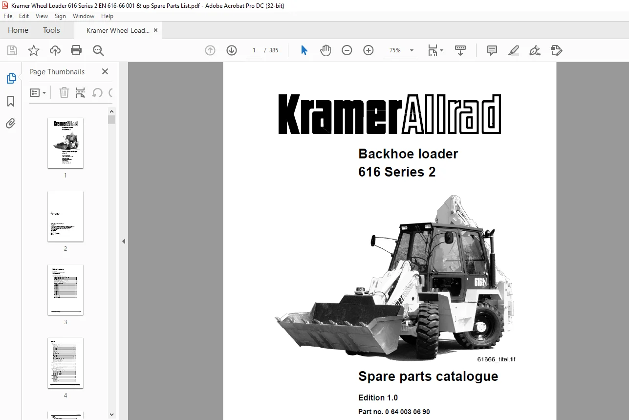
Kramer Allrad Backhoe loader 616 Series 2 Spare parts catalogue Manual SN 616660001 – PDF DOWNLOAD
$28.95
Kramer Allrad Backhoe loader 616 Series 2 Spare parts catalogue Manual SN 616660001 – PDF DOWNLOAD
Description
Kramer Allrad Backhoe loader 616 Series 2 Spare parts catalogue Manual SN 616660001 – PDF DOWNLOAD
FILE DETAILS:
Kramer Allrad Backhoe loader 616 Series 2 Spare parts catalogue Manual SN 616660001 – PDF DOWNLOAD
Language : English
Pages :385
Downloadable : Yes
File Type : PDF
DESCRIPTION:
Kramer Allrad Backhoe loader 616 Series 2 Spare parts catalogue Manual SN 616660001 – PDF DOWNLOAD
Introduction
Please state the following for all spare parts orders:
• Model – serial no. – day of delivery
• Please state the gearbox and the engine number for all spare parts orders
for these components.
• Parts description
• Please state the parts description as set forth in the spare parts list,
e.g. double cardan shaft (short), or cylindrical roller bearing
NJ 208 EC 3 – DIN 5412.
• Spare part number
• The 10-digit spare part number is absolutely necessary, e.g. 0 52 261 01 20
or 7 622 000 081.
• Group number
• This is a 2-digit number, or in the case of optional equipment a 4-digit
number, in bold print at the upper right of each text page, e.g. 26 or
SO 1268.
• Exact indication of quantity to be delivered.
• Exact shipment address and desired shipping mode,
e.g. postal service, rail, air freight, express delivery etc., rail station for rail shipment, postal code for postal service.
If no indications are made, Kramer-Werke GmbH will make shipment at their own discretion
Example for spare parts order:
- For Kramer 616 – serial no. 616 66 0001 – date of delivery: 15.08.99 1 off double cardan shaft (short) – 0 52 261 01 20 – (26) 1 off cylindrical roller bearing NJ 208 EC 3 – DIN 5412 – 7 622 000 081 – (22) Express delivery – London – Victoria station.
- Delivery of spare parts is carried out cash on delivery. Damaged samples sent to KRAMER Werke GmbH will be scrapped if no request for return has been forwarded within 8 days.
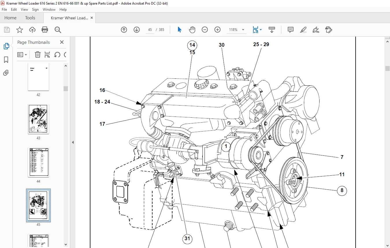
IMAGES PREVIEW OF THE MANUAL:
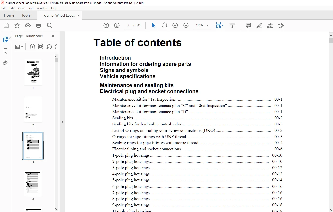
TABLE OF CONTENTS:
Kramer Allrad Backhoe loader 616 Series 2 Spare parts catalogue Manual SN 616660001 – PDF DOWNLOAD
Introduction
Information for ordering spare parts
Signs and symbols
Vehicle specifications
Maintenance and sealing kits
Electrical plug and socket connections
Maintenance kit for “1st Inspection” 00-1
Maintenance kit for maintenance plan “C” and “2nd Inspection” 00-1
Maintenance kit for maintenance plan “D” 00-1
Sealing kits 00-2
Sealing kits for hydraulic control valve 00-2
List of O-rings on sealing cone screw connections (DKO) 00-3
O-rings for pipe fittings with UNF thread 00-3
Sealing rings for pipe fittings with metric thread 00-4
Electrical plug and socket connections 00-6
1-pole plug housings 00-10
2-pole plug housings 00-10
3-pole plug housings 00-12
4-pole plug housings 00-12
5-pole plug housings 00-14
6-pole plug housings 00-16
7-pole plug housings 00-16
8-pole plug housings 00-16
9-pole plug housings 00-18
11-pole plug housings 00-18
13-pole plug housings 00-18
17-pole plug housings 00-18
20-pole plug housings 00-18
21-pole plug housings 00-18
28-pole plug housings 00-18
37-pole plug housings 00-18
Other component parts 00-18
I-2 ET 616 66 En * Edition 1 0 * 61666e0100IVZ fm
Table of contents
Engine
Mounting hardware – component parts 01-2
Engine 01-2
Engine mounting (left) 01-2
Fan bearing 01-2
Alternator 01-4
V-grooved pulley 01-4
Intake manifold 01-4
Fuel pump 01-4
Oil pan 01-4
Cylinder-head cover 01-6
Turbocharger 01-6
Engine mounting (right) 01-8
Clutch 01-8
Engine ventilation 01-8
Engine – component parts 01-10
Injection facility 01-12
Water pump 01-12
Engine – crankshaft – pistons – component parts 01-14
Engine: oil pump – component parts 01-14
Engine: cylinder head – component parts 01-16
Engine: tilt lever – component parts 01-16
Fuel lines
Fuel line – negative wheel castor 08-2
Fuel line – reflux 08-2
Air filter
Standard air filter 10-2
Air filter for operation in dusty environment 0641000099 10-2
Air filter with safety cartridge 0641000199 10-4
Engine cooling
Radiator: attachment – radiator lines – breather line 15-2
Radiator attachment 15-2
Expansion tank – engine breather line 15-4
Expansion tank – radiator line 15-4
Radiator line: engine – radiator (upper) 15-4
Radiator line: engine – radiator (lower) 15-4
Fuel feed system
Fuel feed system 16-2
Fuel tank attachment 16-2
Speed regulation
Speed regulation 17-2
Cutoff device (engine) 17-2
Manual throttle 17-4
Table of contents
ET 616 66 En * Edition 1 0 * 61666e0100IVZ fm I-3
Frame
Floor pan
Rear axle attachment on frame 20-2
Front axle attachment on frame 20-2
Rear excavator attachment on frame 20-2
Oscillating axle lock 20-2
Cover plate 20-4
Cover plates – attachment 20-4
Hydrostatic drive
Variable displacement pump – variable displacement motor – cardan shaft 22-2
Variable displacement pump – variable displacement motor 22-2
Cardan shaft attachment 22-2
Variable displacement pump – variable displacement motor – hydraulic installation 22-4
Component parts for variable displacement pump 22-4
Component parts for variable displacement motor 22-8
Variable displacement pump – variable displacement motor – hydraulic installation 22-10
Suction line: oil tank – variable displacement pump 22-10
SHD- line: variable displacement pump – variable displacement motor 22-10
Control line: variable displace pump PS – variable displace motor X1 22-10
Filter line: variable displace pump Fe – pressure filter – variable displace pump Fa 22-10
Reflux line: case flushing – variable displacement motor T2 – reflux line: steering 22-12
Pressure line: brake pedal – variable displacement pump Z (inching) 22-12
Short circuit line: temperature controller – suction line: variable displacement pump 22-12
Tow away line 22-12
Reflux line: variable displace pump – variable displace motor – oil temp controller 22-12
Reflux line from oil temperature controller to the radiator and to the tank 22-14
Gearbox block – gearbox housing – gearbox parts 22-16
Gearbox (standard) 20 kph SO 1342/1 22-16
Gearbox block: gearbox housing – gearbox components –
Gear shift mechanism for high speed 22-22
Gearbox (high speed gearbox) 39 kph SO 1342 22-22
High speed circuit 22-28
Pressure line: variable displacement pump – solenoid valve A/P 22-28
Pressure line: solenoid valve – ram 22-28
Reflux line: solenoid valve – reflux line – differential lock 22-28
I-4 ET 616 66 En * Edition 1 0 * 61666e0100IVZ fm
Table of contents
Parking brake
Service brake
Brake pedal – brake disc – component parts 24-2
Parking brake – component parts 24-2
Attachment: hand brake-cable pull 24-2
Brake valve – brake line – valves – pressure accumulator – pressure switch 24-6
Brake valve – cut-off valve 24-6
Pressure line: cut-off valve A2 – brake valve A11 – pressure accu and pressure switch 24-6
Pressure line: brake valve A 21 – var displace pump (inching) – double non-return valve 24-8
Pressure line: Double non-return valve – front axle (left and right) 24-8
Pressure line: output screw connection evT – brakes – rear axle (left and right) 24-10
Reflux line: brake valve A 51 – oil tank 24-10
Reflux line: hand brake valve – brake valve 24-10
Pressure line: hand brake valve – brake valve 24-12
Pressure line: double non-return valve – hand brake valve 24-12
Planetary steering axles
Component parts: axle – differential lock – steering ram 26-2
Rear axle – front axle 26-2
Component parts: axle – differential lock – steering ram 26-4
Component parts (bevel gear set) 26-4
Component parts (differential case) 26-8
Component parts: axle – differential lock – steering ram 26-10
Components parts: axle casing 26-10
Component parts for front axle only 26-14
Component parts – joint housing 26-16
Component parts for double cardan shaft 26-16
Component parts: axle – differential lock – steering ram 26-18
Component parts: output and brake 26-18
Component parts: steering ram 26-22
Differential lock control – hydraulic installation 26-24
Differential lock control 26-24
Pressure line – output pressure filter: solenoid valve – differential lock – front axle 26-24
Pressure line – output screw connection evT – differential lock – rear axle 26-24
Reflux line: solenoid valve – reflux line – oil tank 26-24
Table of contents
ET 616 66 En * Edition 1 0 * 61666e0100IVZ fm I-5
Steering
Hydrostatic steering: hydraulic pump – solenoid valve – valves – oil pipes 27-2
Steering – component parts 27-2
Suction line: hydraulic oil tank – steering pump 27-2
Hydraulic pump for steering 27-2
Pressure line: steering pump – cut-off valve – steering 27-4
Pressure line: steering (output L) to check valve L 27-6
Pressure line: steering (output R) – to check valve R 27-6
Check valve A – change-over valve P – steering ram (rear right ) 27-6
Check valve S – change-over valve T – steering ram (rear left) 27-6
Anticavitation – steering ram – rear axle 27-8
Pressure line: check valve B – steering ram front axle L 27-8
Pressure line: check valve S – steering ram – front axle R 27-8
Hydrostatic steering: hydraulic pump – solenoid valve – valves – oil pipes 27-10
Reflux line: steering (output T) – to hydraulic oil filter 27-10
Reflux line: case flushing – variable displacement motor T2 – reflux line steering 27-10
Anticavitation line for steering 27-10
Reflux line: check valve – reflux line – brake valve 27-10
Steering synchronization 27-12
Component parts for check valve and solenoid valve 27-14
Component parts for check valve 27-14
Component parts for solenoid valve 27-14
Operator’s seat
Component parts: operator’s seat 29-2
Operator’s seat 29-2
Operator’s seat – component parts 29-2
Operator’s seat – optional component parts 29-2
Operator’s seat – leatherette upholstery 29-2
Operator’s seat – lower part 29-4
Component parts: seat adjustment 29-6
Seat adjustment – component parts 29-6
Sheet-metal parts
Cover plates – wheel cover (front and rear) 30-2
Sheet-metal parts 30-2
Rubber cover between wheel covers 30-4
Parts as per German road use registration for high speed gearbox SO 1067/4
(possibly necessary depending on the legal regulations of your country) 30-6
Tyres – snow chains
Standard tyres 31-2
Optional tyres 31-2
Snow chains SO 1295 09 for tyres 16/70-24 31-2
Exhaust system
Exhaust silencer – rear silencer – cover plate 32-2
Exhaust system – component parts 32-2
Attachment: exhaust silencer on the cab 32-2
I-6 ET 616 66 En * Edition 1 0 * 61666e0100IVZ fm
Table of contents
Electrical system
Instrument panel – side console – telltales – switch 33-2
Front instrument panel – component parts 33-2
Instrument panel: side console – component parts 33-8
Headlight: switch – starter – alternator – battery cable 33-10
Vehicle lighting 33-10
Rear light on cab – SO 1380/00 33-10
Counterweight SO 580/04 33-10
Starter – alternator – battery 33-12
Steering synchronization 33-14
Wiring harnesses – component parts 33-16
Wiring harness: instrument panel (side console) 33-16
Wiring harness: instrument panel (front) 33-18
Main wiring harness 33-20
Front wiper 33-26
Washer system (front) 33-26
Wiper on the rear window 33-26
Washer system (rear) 33-26
Rotating beacon 33-28
Rotating beacon attached on the cab SO 01206/15 33-28
Additional light attached on the cab (front) – SO 01382/00 33-28
Electric equipment for front implement 33-30
Socket for external auxiliary starting 33-30
Engine preheater 220 V 33-30
Table of contents
ET 616 66 En * Edition 1 0 * 61666e0100IVZ fm I-7
Cab
Cab: cab parts 34-2
Front window – rear window – exterior rearview mirror 34-2
Cab: component parts 34-2
Sealing on the cab (front) – mount 34-2
Rear window (upper) 34-4
Rear window (lower) 34-4
Cab doors 34-6
Cab doors (lower) 34-6
Cab doors (upper) 34-8
Detent for cab door (upper) 34-8
Component parts: cab – centre console – side console 34-10
Cab: component parts 34-10
Cab: roof 34-12
Cab – roof 34-12
Special roof with window and protective screen for fork lift truck SO 596 01 34-12
Roof with protective FOPS screen and aluminium roof hatch SO 596 02 34-12
Engine cover – component parts – attachment 34-14
Engine cover: attachment 34-14
Sheet-metal parts – insulating mat 34-16
Floor panels – insulating mat 34-16
Interior lining 34-20
Interior lining (rear – excavator desk and leg room) 34-20
Cab: attachment 34-22
Attachment: cab 34-22
Passenger’s seat (left) – SO 579 01 34-22
Folding seat 00579-03 34-22
I-8 ET 616 66 En * Edition 1 0 * 61666e0100IVZ fm
Table of contents
Hydraulic system
Hydraulic pump drive – hydraulic pump for loader unit 36-2
Oil tank 36-2
Reflux filter 36-2
Breather 36-4
Suction line: oil tank – hydraulic pump for loader unit 36-4
Pressure line from hydraulic pump to control valve 36-4
Reflux line from control valve to oil tank 36-4
Micro port line: control valve 36-6
Control valve (component parts see page 36-18) 36-6
Hydraulic pump for rear excavator 36-8
Suction line: oil tank – hydraulic pump – rear excavator 36-10
Pressure line: hydraulic pump rear excavator – control valve rear excavator 36-10
Attachment: pressure line to the vehicle 36-10
Pressure transmission: control valve – pressure line rear excavator 36-10
Reflux line: rear excavator – oil tank 36-10
Component parts for control valves 36-12
Control valve actuation 36-12
Attachment: control valve 36-14
Component parts for control lever 36-16
Control valve – component parts 36-18
Pressure line: control valve – lift ram (raise) – solenoid valve B 36-20
Pressure line: control valve – lift ram (lower) – solenoid valve A 36-20
Pressure line: solenoid valve PB – pressure accumulator 36-22
Output: line – pressure accumulator – pressure relief valve 36-22
Reflux line: solenoid valve PA – pressure relief valve – reflux steering 36-22
Control: load stabilizer – with rocker switch on the instrument panel 36-22
Pressure line: control valve – tilt ram (tilt in) 36-24
Pressure line: control valve – tilt ram (dump out) 36-24
Pressure line: control valve – 3rd control circuit 36-26
Lift frame, tilt lever, tilt rod, bearings 36-28
Lift frame, lift frame bearing, lift and tilt ram bearing 36-28
Bearing: lift frame on vehicle frame 36-28
Attachment: lift ram on vehicle frame 36-28
Attachment: tilt ram on vehicle frame 36-28
Attachment: tilt rod on the tilt lever 36-30
Attachment: tilt ram on the rocker lever 36-30
Attachment: tilt lever and lift ram on the lift frame 36-30
Attachment: quickhitch facility on the lift frame 36-30
Attachment: quickhitch facility on tilt rod 36-30
Lift ram: tilt ram 36-32
Lift ram: component parts 36-32
Tilt ram – component parts 36-34
Quickhitch – hydraulic ram – hydraulic installation 36-36
Quickhitch 36-36
Hydraulic installation (control ram – quickhitch facility – lift frame) 36-36
Hydraulic ram on quickhitch facility Üy approximately March 2000 36-38
Hydraulic ram on quickhitch facility yÜ approximately April 2000 36-38
Table of contents
ET 616 66 En * Edition 1 0 * 61666e0100IVZ fm I-9
Restrictor unit on tilt ram 01388-00 36-40
Hose burst valve for lift ram 36-42
Hose burst valve for tilt ram 36-42
Hose burst valve with ball-type cock and cover for lift ram 36-44
Hose burst valve with ball-type cock and cover for tilt ram 36-44
Attachments for fork lift mast model 0126611 36-46
Cab heating
Heating and ventilation
Component parts for heater fan – feed and reflux line to engine 41-2
Cab heating 41-2
Cab heating D1L C Eberspächer 41-6
Vehicle heater 41-6
Buckets for
quickhitch facility
Bucket for Kramer quickhitch facility SO 01339-13/14 41/3-2
Bucket for Kramer quickhitch facility SO 10049-00 41/3-2
Lightweight material bucket for Kramer quickhitch facility SO 01339-15 41/3-2
Component parts of multipurpose bucket 41/3-4
Multipurpose bucket for Kramer quickhitch facility SO 01339-03/04 41/3-4
Hydraulic installation – hydraulic ram 41/3-6
Hydraulic installation: multipurpose bucket for Kramer quickhitch facility 41/3-6
Lift ram: version A 41/3-8
Lift ram, version B 41/3-10
Lifting devices for quickhitch facility
Pallet forks for Kramer quickhitch facility SO 01339-09/12 41/4-2
Pallet forks for Kramer quickhitch facility SO 01339-29 41/4-2
Pallet forks for Kramer quickhitch facility SO 10094-00 41/4-2
Tools, additional equipment and keys
Labels, trim strips 43-2
Labels for special oils 43-2
Tool kit 43-4
Key (state key no for all spare parts orders) 43-4
Safety package SO 1151/1 43-6
Antitheft protection 43-6
Additional equipment for application in an agressive environment 43-6
Contact us: [email protected]
https://vimeo.com/845878283?share=copy
PLEASE NOTE:
- This is the same manual used by the dealers to diagnose and troubleshoot your vehicle
- You will be directed to the download page as soon as the purchase is completed. The whole payment and downloading process will take anywhere between 2-5 minutes
- Need any other service / repair / parts manual, please feel free to contact [email protected] . We still have 50,000 manuals unlisted
s.m