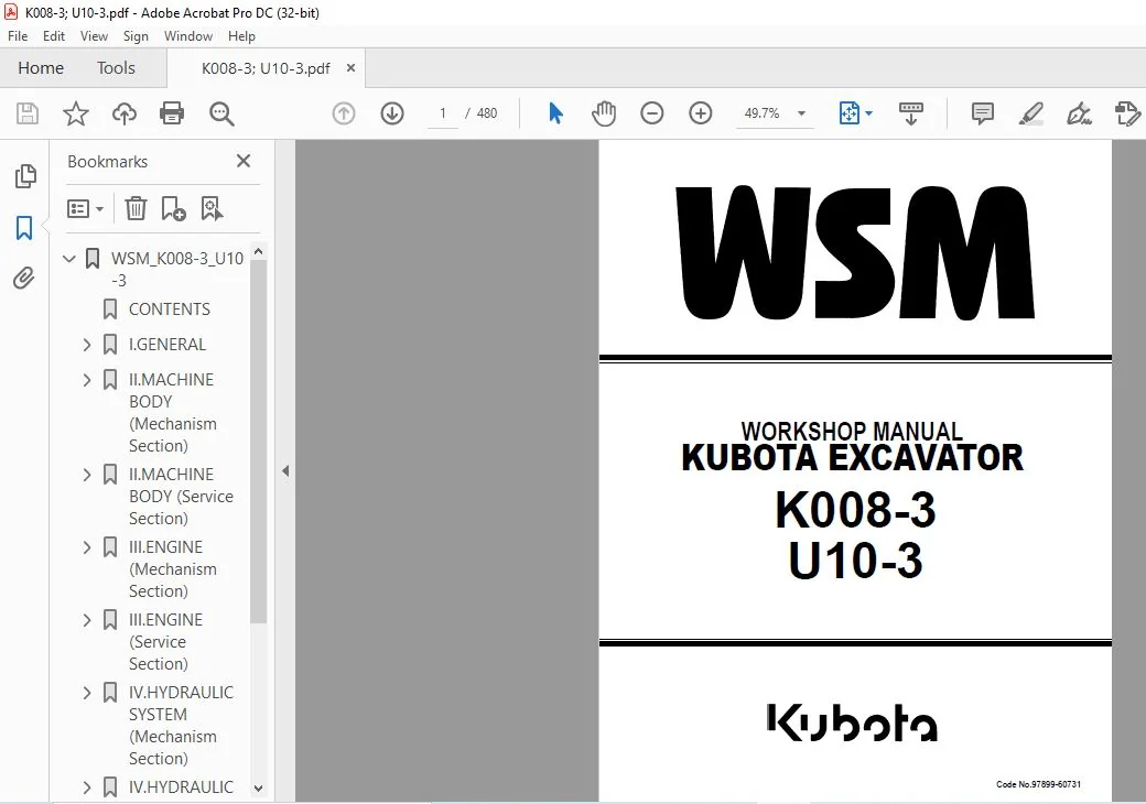
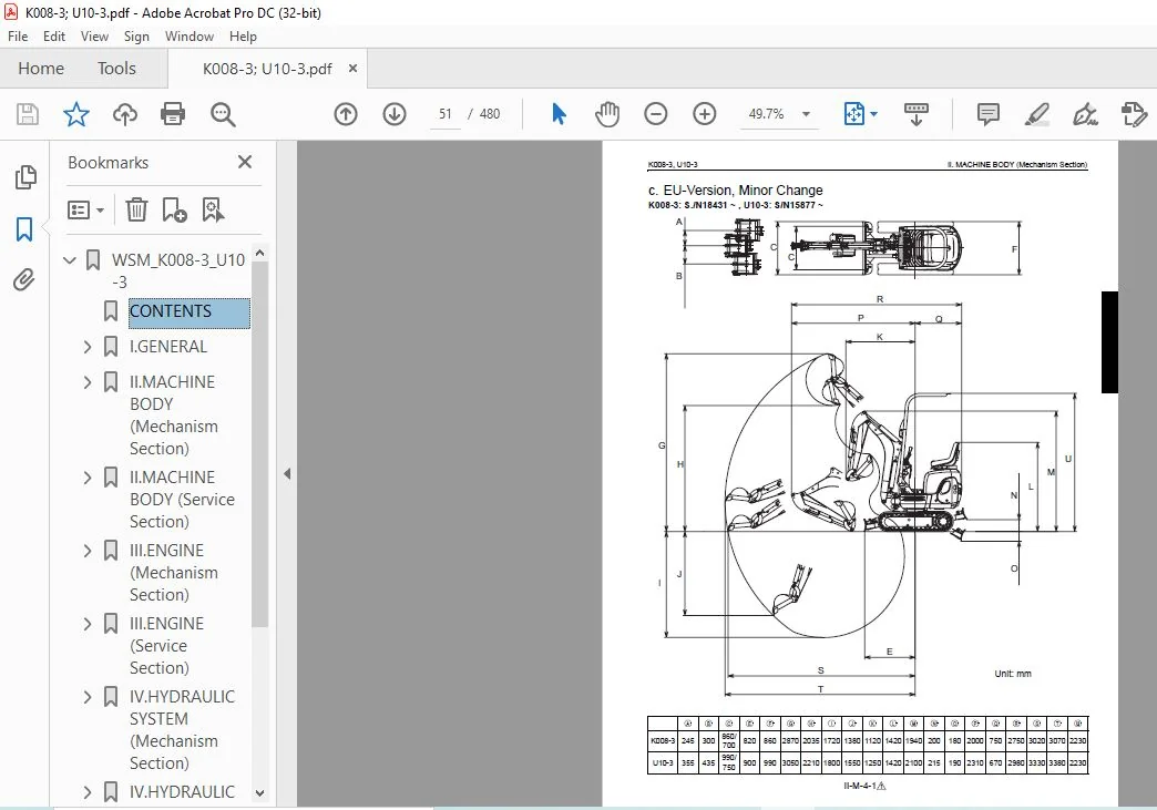
Kubota Excavator K008-3 U10-3 Workshop Service Manual – PDF DOWNLOAD
Original price was: $75.95.$29.95Current price is: $29.95.
Kubota Excavator K008-3 U10-3 Workshop Service Manual – PDF DOWNLOAD
Description
Kubota Excavator K008-3 U10-3 Workshop Service Manual – PDF DOWNLOAD
DESCRIPTION:
Kubota Excavator K008-3 U10-3 Workshop Service Manual – PDF DOWNLOAD
Safety precautions for disassembly and reassembly :
Machines must be disassembled and assembled efficiently and safely.
It is very important to thoroughly understand the construction and function of the machine, to make all appropriate preparations, and start operations according to the specified working procedures.
a. Safety Measures before Starting Work
(1)Work clothes
1. Wear specified work cap and clothed.
(Under no circumstances may workers wear undershirts only.) Cuffs must be kept buttoned, and any tears must be mended.)
2. Wear safety shoes.
3. Do not wear cotton gloves when working on the internal section of engine, reduction gears or hydrauricunits for repair or others, or when using a hammer. Wear leather gloves, however, when hoisting wires.
(2)Inspecting equipment and tools
1. Prepare equipment (cranes, fork lifts, tool,
etc.) required for servicing and inspect for
any problems before starting work.
2. Hammer heads (metal parts) must be firmly
secured to their handles.
3. Check hosting tools (wire ropes, hoisting
chains, etc.) before use.
(3)Keep workshop in order
1. Secure appropriate space needed for disassembly to the job.
2. Secure a clean, safe place for arranging disassembled parts.
3. Store volatile substances (gasoline, light oil,
thinner, oily articles, etc.) in appropriate containers
at selected locations to prevent fire
hazards.
b. Safety Measures during Work
(1)Protectors
1. Wear goggles when using chisels for chipping.
2. Use appropriate protectors during welding.
3. Wear a helmet when working with a crane or
at elevated locations.
(2)Team work
1. When working with two or more people,
divide the work and maintain close communication.
2. Clane work must be carried out using predetermined
signals.
(3)Disassembly and assembly
1. Do not wear gloves when using hammers.
2. Use rods of the specified soft material for
removing pins. Do not use a hammer as a
pad.
3. Do not place fingers in holes when centering.
4. Heavy parts must be adequately supported
before removingbolts.
(4)Cranes
1. In principle, use a crane for objects heavier
than 44lb (20kg).
2. Crane operation and hoisting must be performed
only by qualified personal.
3. Pay careful attention to the center of gravity
when hoisting, and do not stand under the
lifted objects.
(5)Others
1. To work under a jacked-up carrier, be sure to
place wood pieces under it.
2. When charging batteris, make sure there are
no open flames in the immediate vicinity.
3. All electric tools must be grounded.
4. Before welding the machine, remove the
battery.
• When removing the battery, be sure to disconnect
negative (-) cord first.
• When mounting the battery, be sure tp
connect the positive (+) cord first.
IMAGES PREVIEW OF THE MANUAL:


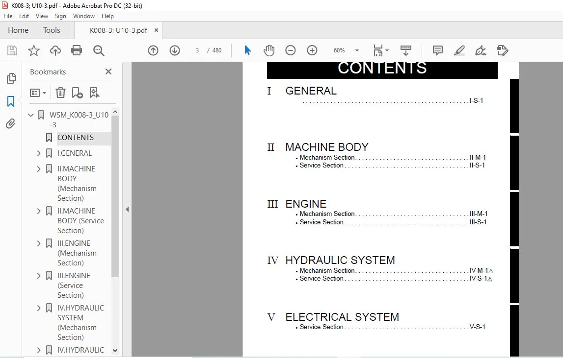
TABLE OF CONTENTS:
Kubota Excavator K008-3 U10-3 Workshop Service Manual – PDF DOWNLOAD
WSM_K008-3_U10-3...........................................................  1
	CONTENTS...............................................................  3
	I.GENERAL..............................................................  4
		A. BODY AND ENGINE IDENTIFICATION MARKS............................  5
		B. SAFETY PRECAUTIONS FOR SERVICING, DISASSEMBLY AND REASSEMBLY....  7
			a. Safety Measures before Starting Work........................  7
			b. Safety Measures during Work.................................  7
			c. Preparation for Disassembly.................................  8
			d. Precautions for Disassembly and Reassembly..................  8
			e. Maintenance.................................................  8
			f. Waste Disposal..............................................  8
		C. IMPORTANT SAFETY PROCESS AND CRITICAL FUNCTIONAL PROCESS........  9
			a. Essential Adhesives.........................................  9
			b. Important Safety Process....................................  9
			c. Important Critical Functional Process.......................  9
		D. IMPORTANT INSPECTION ITEMS AFTER REASSEMBLING................... 11
		E. SERVICING FUNDAMENTALS.......................................... 13
			a. Items for Servicing......................................... 13
			b. O-ring, Oil Seal, Circlip and Roll Pin...................... 15
			c. Piping...................................................... 17
		F. MACHINE QUALITY SPECIFICATIONS.................................. 23
			a. K008-3, U10-3 EU-Version.................................... 23
			b. K008-3 KTC, KCL, KTA-Version................................ 28
		G. MAINTENANCE INTERVALS........................................... 35
			a. K008-3, U10-3 EU-version.................................... 35
			b. K008-3, U10-3 KTC, KCL-Version.............................. 36
			c. K008-3, U10-3 KTA-Version................................... 37
			d. Periodic Replacement of Important Component Parts........... 38
			e. Hydraulic Oil Check for Machines with Hydraulic Breakers.... 39
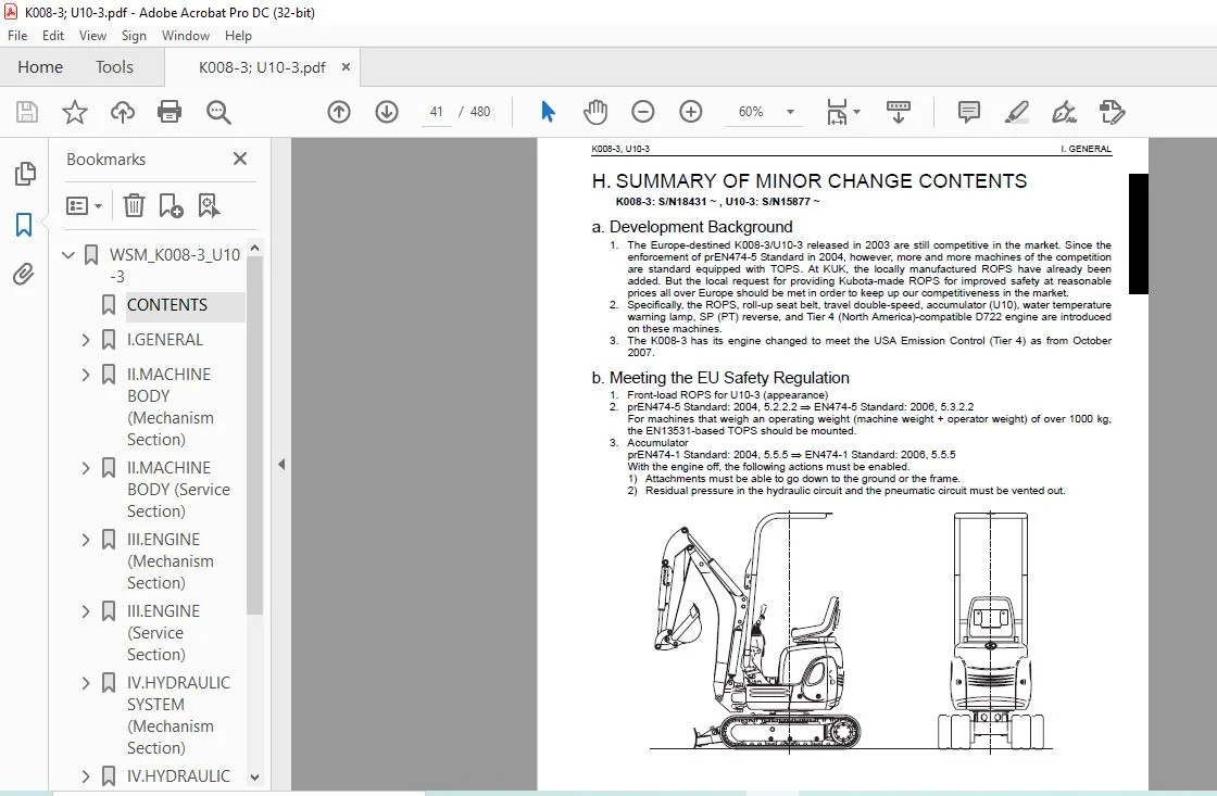
		H. SUMMARY OF MINOR CHANGE CONTENTS................................ 41
			a. Development Background...................................... 41
			b. Meeting the EU Safety Regulation............................ 41
			c. Main Items of Minor Change.................................. 42
			d. Main Performance Specifications and Comparison.............. 43
	II.MACHINE BODY (Mechanism Section).................................... 47
		A. SPECIFICATIONS.................................................. 49
			a. EU-Version.................................................. 49
			b. KTC, KCL, KTA-Version....................................... 50
			c. EU-Version, Minor Change.................................... 51
		B. COMPONENT INTERCHANGEABILITY.................................... 11
			a. Bucket...................................................... 11
		C. MACHINE STRUCTURE............................................... 55
			a. Control Linkage............................................. 55
			b. Engine Mount................................................ 60
			c. Undercarriage............................................... 61
	II.MACHINE BODY (Service Section)...................................... 65
		A. SPECIFICATIONS.................................................. 67
			a. Machine Weight.............................................. 67
			b. Machine Specifications...................................... 68
			c. Lever Stroke and Operating Force............................ 70
			d. Dimensions of Parts......................................... 72
		B. FRONT ATTACHMENT................................................ 81
			a. Front Attachment Assembly Procedure......................... 81
			b. Greasing Points............................................. 84
			c. Shim Adjustment............................................. 85
		C. UPPER STRUCTURE................................................. 87
			a. Operating Unit.............................................. 87
			b. Dozer Lever................................................. 93
			c. Swing Pedal................................................. 95
			d. Service Port Pedal.......................................... 97
			e. TPSS (Two Pattern Selection System).........................100
			f. Weight......................................................103
			g. ROPS (Rear Mount Type)......................................105
			h. Seat Belt Setup Angle (Rear Mount Type).....................108
			i. ROPS (Front Mount Type) (EU-Version)........................109
			j. Seat Belt (EU-Version)......................................111
		D. UNDERCARRIAGE...................................................113
			a. Swivel Bearing..............................................113
			b. Traveling Unit..............................................117
			c. Drive Sprocket..............................................121
			d. Track Frame (Retractable - version).........................122
	III.ENGINE (Mechanism Section).........................................127
		A. SAFETY FIRST....................................................129
		B. ENGINE SPECIFICATIONS FOR CONSTRUCTION MACHINERY................131
		C. ENGINE ELECTRIC COMPONENTS......................................133
		D. ENGINE CHANGE FOR EPA EMISSION CONTROL..........................135
		E. PERFORMANCE CURVE...............................................137
		F. DIMENSION.......................................................139
	III.ENGINE (Service Section)...........................................165
		A. TANK............................................................167
		B. ENGINE MOUNT ON THE MACHINE.....................................175
		C. GENERAL.........................................................177
	IV.HYDRAULIC SYSTEM (Mechanism Section)................................245
		A. MAIN PUMP (K008-3, U10-3).......................................247
		B. PILOT PUMP (U10-3)..............................................249
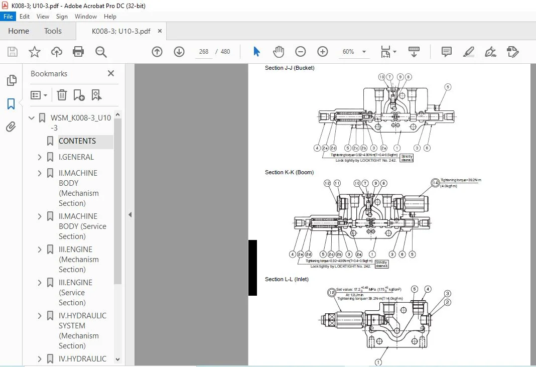
		C. CONTROL VALVE...................................................251
			a. Specifications..............................................251
			b. General View of Control Valve...............................253
			c. Sectional View..............................................257
			d. Structure and Function......................................269
		D. PILOT VALVE.....................................................271
			a. Structure...................................................271
			b. Pilot Valve Control Diagram.................................273
			c. Function....................................................274
		E. HYDRAULIC PILOT CIRCUIT.........................................277
			a. Oil Flow when the Control Lever is Locked (A)...............278
			b. Oil Flow when the Control Lever is Locked (B)...............280
			c. Oil Flow in Boom Lifting Operation..........................282
			d. Oil Flow in Bucket Dumping Operation........................284
			e. Oil Flow in Arm Crowding Operation..........................286
			f. Oil Flow in Right Swivel Operation..........................288
		F. SWIVEL MOTOR (K008-3, U10-3)....................................291
			a. Structure and Specifications................................291
			b. Operating Principle.........................................293
		G. ROTARY JOINT (SWIVEL JOINT).....................................295
		H. TRAVEL MOTOR....................................................297
			a. Single Speed Motor (K008, EU-Version).......................297
			b. Two Speed Motor.............................................300
		I. ORBITROL MOTOR: STRUCTURE & FUNCTION............................303
			a. Basic Function..............................................303
			b. Structure & Function: Shaft Output Type.....................305
			c. Structure & Function: Ring Output Type......................314
		J. HYDRAULIC CIRCUIT DIAGRAM.......................................325
			a. K008-3: Travel 1st Speed Type...............................325
			b. K008-3: Travel 2nd Speed Type...............................326
			c. U10-3: Travel 1st Speed Type................................327
			d. U10-3: Travel 2nd Speed Type................................328
			e. Hydraulic Components Layout: K008-3.........................329
	IV.HYDRAULIC SYSTEM (Service Section)..................................331
		A. TROUBLESHOOTING.................................................333
			a. Machine General.............................................333
			b. Hydraulic System............................................336
		B. SPECIFICATIONS..................................................341
			a. Pump System.................................................341
			b. List of Relief Valves.......................................343
			c. Noise.......................................................344
			d. Swivel System...............................................345
			e. Traveling System............................................346
			f. Cylinder System.............................................347
		C. TESTING.........................................................351
			a. Pump Flow Test..............................................351
			b. Pilot Pressure (U10-3)......................................352
			c. Main Relief Valve Pressure..................................353
			d. Operating Speed.............................................354
			e. Travel Straightness Measurement Test........................357
			f. Traveling Motor Block Performance...........................357
			g. Swivel Motor Block Performance..............................358
			h. Cylinder Natural Fall Amount................................358
			i. Control and Traveling Lever Operating Force.................359
			j. Lever Stroke................................................359
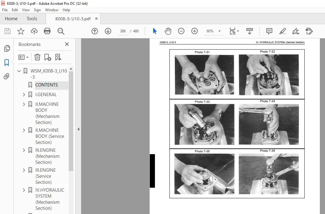
		D. DISASSEMBLING AND ASSEMBLING....................................361
			a. Pump Coupling...............................................361
			b. Pump........................................................362
			c. Control Valve...............................................367
			d. Pilot Valve.................................................370
			e. U10-3 Component Parts of Hydraulic Operating Unit...........371
			f. Pilot Valve.................................................376
			g. Swivel Motor................................................390
			h. Swivel Joint................................................402
			i. Wheel Motor.................................................406
			j. Cylinder....................................................423
			k. Route of Hydraulic Hose.....................................429
			l. Accumulator.................................................438
			m. Tank........................................................439
			n. Service Port Operation......................................440
	V.ELECTRICAL SYSTEM (Service Section)..................................443
		A. WIRING DIAGRAM..................................................445
			a. K008-3, U10-3...............................................445
			b. Wiring Diagram, K008-3, U10-3...............................446
		B. ELECTRIC WIRING.................................................447
			a. Cautions on Electric Wire Clamping Method...................447
			b. Harness Route...............................................447
		C. TROUBLESHOOTING OF ELECTRIC SYSTEM..............................455
			a. Outline of Troubleshooting..................................455
			b. Cautions in General.........................................456
			c. Troubleshooting.............................................461
			d. Checking Procedure..........................................463
	Conversion Tables......................................................477
KUBOTA EXCAVATOR K008-3 U10-3 WORKSHOP SERVICE MANUAL – PDF DOWNLOAD:
PLEASE NOTE:
- This is the same manual used by the DEALERSHIPS to SERVICE your vehicle.
- The manual can be all yours – Once payment is complete, you will be taken to the download page from where you can download the manual. All in 2-5 minutes time!!
- Need any other service / repair / parts manual, please feel free to contact us at heydownloadss @gmail.com . We may surprise you with a nice offer
S.V