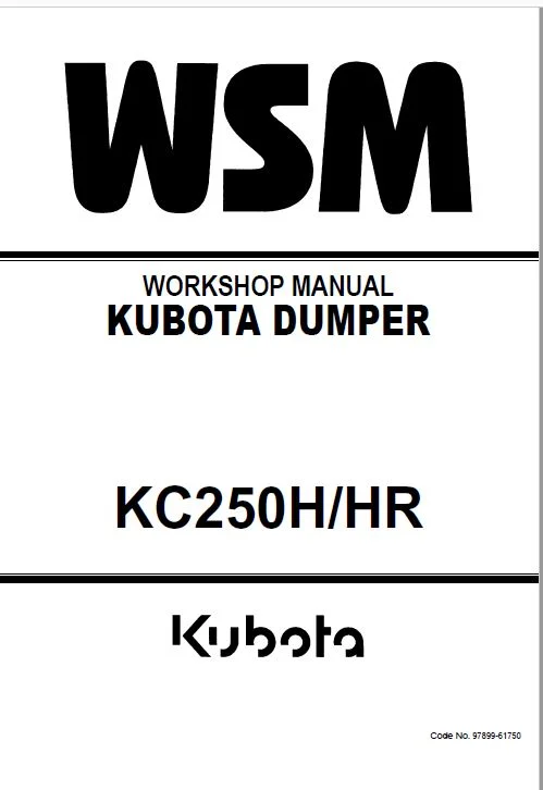
Kubota KC250H HR DUMPER Workshop Manual – PDF DOWNLOAD
Original price was: $98.95.$26.95Current price is: $26.95.
Kubota KC250H HR DUMPER Workshop Manual – PDF DOWNLOAD
Description
Kubota KC250H HR DUMPER Workshop Manual – PDF DOWNLOAD
DESCRIPTION:
Kubota KC250H HR DUMPER Workshop Manual – PDF DOWNLOAD
1. Introduction
1.1 Purpose of This Manual
The purpose of this manual is to provide the technician with detailed information so that they will
know the structure and proper method of servicing concerning this machine.
This manual has been prepared for people who are familiar with how to operate and control this
machine.
1.2 Composition of This Manual
This manual gives information by dividing it into the following chapters:
1. Introduction
This Chapter describes the purpose and formation of this manual and information and data
necessary for the maintenance of this vehicle.
2. Service Data
This Chapter describes the names and functions of the parts, specification, and product
number position of this vehicle.
3. Removal and Installation of Covers
This Chapter describes the formation of the safety covers installed in this vehicle.
4. Engine
This Chapter describes the information on the dismounting of the engine.
5. Driveline and Chassis
This Chapter describes the information on the structure and maintenance (disassembly,
reassembly, adjustment) of the driveline and chassis.
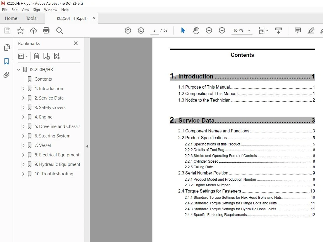
TABLE OF CONTENTS:
Kubota KC250H HR DUMPER Workshop Manual – PDF DOWNLOAD
1. Introduction ………………………………………………… 1
1.1 Purpose of This Manual…………………………………………………………….1
1.2 Composition of This Manual ………………………………………………………1
1.3 Notice to the Technician ……………………………………………………………2
2. Service Data………………………………………………… 3
2.1 Component Names and Functions ……………………………………………..3
2.2 Product Specifications ………………………………………………………………5
2.2.1 Specifications of this Product …………………………………………………………….. 5
2.2.2 Details of Tool Bag …………………………………………………………………………… 8
2.2.3 Stroke and Operating Force of Controls………………………………………………. 8
2.2.4 Cylinder Speed ………………………………………………………………………………… 8
2.2.5 Falling Rate …………………………………………………………………………………….. 8
2.3 Serial Number Position……………………………………………………………..9
2.3.1 Product Model and Production Number ………………………………………………. 9
2.3.2 Engine Model Number………………………………………………………………………. 9
2.4 Torque Settings for Fasteners ………………………………………………….10
2.4.1 Standard Torque Settings for Hex Head Bolts and Nuts ………………………. 10
2.4.2 Standard Torque Settings for Flange Bolts and Nuts …………………………… 11
2.4.3 Standard Torque Settings for Hydraulic Hose Joints……………………………. 11
2.4.4 Specific Fastening Requirements ……………………………………………………… 12
2.5 Fuel, Lubricant, and Cooling Water Chart ………………………………….12
2.6 Consumables (Replacement Parts) Chart ………………………………….13
3. Safety Covers ……………………………………………. 14
3.1 Removing Safety Covers…………………………………………………………14
4. Engine ………………………………………………………. 16
4.1 Removing Engine …………………………………………………………………..16
5. Driveline and Chassis………………………………… 17
5.1 Driveline Mechanism ………………………………………………………………17
5.2 Chassis Mechanism ……………………………………………………………….18
5.3 Parts Diagrams and Summaries of Assembly and Adjustment ……..18
5.3.1 Idler………………………………………………………………………………………………. 18
5.3.2 Roller A (mobile roller) …………………………………………………………………….. 19
5.3.3 Roller B (fixed roller)……………………………………………………………………….. 20
5.3.4 Upper roller (carrier roller) ……………………………………………………………….. 21
5.3.5 Track Tension Adjuster……………………………………………………………………. 22
5.3.6 Tips for Track Tension Adjustment……………………………………………………. 23
5.3.7 Rubber track ………………………………………………………………………………….. 23
5.4 Maintenance Standard of the Parts …………………………………………..24
5.4.1 Idler………………………………………………………………………………………………. 24
5.4.2 Roller A (Mobile Roller)/Roller B (Fixed Roller) …………………………………… 24
5.4.3 Upper Roller ………………………………………………………………………………….. 25
5.4.4 Sprocket ……………………………………………………………………………………….. 25
5.4.5 Rubber Track…………………………………………………………………………………. 25
6. Steering System………………………………………… 26
6.1 Steering System Diagram………………………………………………………..26
6.2 Adjustment of the Steering System …………………………………………..27
6.2.1 Neutrality Adjustment ……………………………………………………………………… 27
6.2.2 6.2.2 Linearity Adjustment ……………………………………………………………….. 27
7. Vessel……………………………………………………….. 29
7.1 Tail Gate Closing Mechanism…………………………………………………..29
8. Electrical Equipment………………………………….. 30
8.1 Electrical Diagram ………………………………………………………………….30
8.2 Tips for Mechanism, Functions, and Maintenance ………………………32
8.2.1 Indicator………………………………………………………………………………………… 32
8.2.2 Fuel Level Sensor…………………………………………………………………………… 33
8.2.3 Ignition switch ………………………………………………………………………………… 33
8.2.4 Switch (Parking Brake, High/Low Speed, Light)………………………………….. 33
8.2.5 Horn Switch …………………………………………………………………………………… 34
8.2.6 Relay ……………………………………………………………………………………………. 34
8.3 Tips for Operational Confirmation……………………………………………..36
9. Hydraulic Equipment …………………………………. 37
9.1 Circuit Diagram………………………………………………………………………37
9.1.1 One-way Dump Model …………………………………………………………………….. 37
9.1.2 Turn & Dump Model ………………………………………………………………………. 38
9.2 Mechanism, Function, and Specification ……………………………………39
9.2.1 HST Pump…………………………………………………………………………………….. 39
9.2.2 HST Motor (Traveling Motor)……………………………………………………………. 40
9.2.3 Control Valve …………………………………………………………………………………. 41
9.2.4 Solenoid Valve……………………………………………………………………………….. 42
9.3 Tips and Maintenance Standards for HST Circuit ……………………….43
9.3.1 Pressure Setting Standards……………………………………………………………… 43
9.3.2 Neutrality adjustment………………………………………………………………………. 44
9.4 Towing ………………………………………………………………………………….46
10. Troubleshooting ……………………………………… 47
10.1 The Engine does not Start ……………………………………………………..47
10.2 Vehicle does not Move with Lever Engagedand Parking Brake
Unhitched. ………………………………………………………………………………….48
10.3 Lever Response is Slow. ………………………………………………………49
10.4 Unable to Make a Pivot Turn (Unable to Lock One Track). …………49
10.5 Unable to Travel Straight. ……………………………………………………..50
10.6 Unable to Turn to Either Side. ………………………………………………..50
IMAGES PREVIEW OF THE MANUAL:
PLEASE NOTE:
- This is the same manual used by the dealers to diagnose and troubleshoot your vehicle
- You will be directed to the download page as soon as the purchase is completed. The whole payment and downloading process will take anywhere between 2-5 minutes
- Need any other service / repair / parts manual, please feel free to contact [email protected] . We still have 50,000 manuals unlisted
S.V