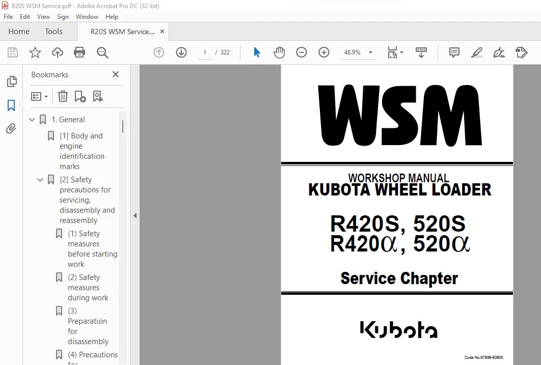
Kubota R420S 520S R420α 520α Wheel Loader Workshop Manual – PDF DOWNLOAD
Original price was: $89.95.$28.95Current price is: $28.95.
Kubota R420S 520S R420α 520α Wheel Loader Workshop Manual – PDF DOWNLOAD
Description
Kubota R420S 520S R420α 520α Wheel Loader Workshop Manual – PDF DOWNLOAD
DESCRIPTION:
Kubota R420S 520S R420α 520α Wheel Loader Workshop Manual – PDF DOWNLOAD
(1) Safety measures before starting work :
[1] Work clothes
1. Wear specified work cap and clothed. (Under no circumstances may workers wear undershirts only.)
Cuffs must be kept buttoned, and any tears must be mended.)
2. Wear safety shoes.
3. Do not wear cotton gloves when working on the internal section of engine, reduction gears or hydraulic units for
repair or others, or when using a hammer. Wear leather gloves, however, when hoisting wires.
[2] Inspecting equipment and tools
1. Prepare equipment (cranes, fork lifts, tool, etc.) requires for servicing and inspect for any problems before
starting work.
2. Hammer heads (metal parts) must be firmly secured to their handles.
3. Check hosting tools (wire ropes, hosting chains, etc.) before use.
[3] Keep workshop in order
1. Secure appropriate space needed for disassembly to the job.
2. Secure a clean, safe place for arranging disassembled parts.
3. Store volatile substances (gasoline, light oil, thinner, oily articles, etc.) in appropriate containers at selected
locations to prevent fire hazards.
(1) Safety measures before starting work
[1] Protectors
1. Wear goggles when using chisels for chipping.
2. Use appropriate protectors during welding.
3. Wear a helmet when working with a crane or at elevated locations.
[2] Team work
1. When working with two or more people, divide the work and maintain close communication.
2. Clean work must be carried out using predetermined signals.
TABLE OF CONTENTS:
Kubota R420S 520S R420α 520α Wheel Loader Workshop Manual – PDF DOWNLOAD
1. General……………………………………………………………………………… 5
[1] Body and engine identification marks……………………………………………….. 5
[2] Safety precautions for servicing, disassembly and reassembly………………………….. 6
(1) Safety measures before starting work……………………………………………. 6
(2) Safety measures during work……………………………………………………. 6
(3) Preparation for disassembly……………………………………………………. 7
(4) Precautions for disassembly and reassembly………………………………………. 7
[3] Important safety process and critical functional process……………………………… 8
[4] Important inspection items after reassembling……………………………………….. 9
(1) Operate the machine and check for unusual noise and vibrations…………………….. 9
(2) Make sure the safety decals and wireharness clamps are in their specified positions….. 9
(3) With the machine front in a specified posture, check the amount of hydraulic oil…….. 9
[5] Service fundamentals……………………………………………………………… 10
(1) Service intervals…………………………………………………………….. 10
(2) Lubricants…………………………………………………………………… 12
(3) Notices for servicing items……………………………………………………. 13
(4) Tightening torque…………………………………………………………….. 14
2. Machine Body & Front Attachment………………………………………………………… 23
[1] Specifications…………………………………………………………………… 23
(1) Machine Specifications………………………………………………………… 23
(2) Main Specification: EU-version…………………………………………………. 25
[2] Installing the frame-related parts (front)………………………………………….. 35
[3] Center pin (important functional component)…………………………………………. 36
[4] Rear frame, center pin……………………………………………………………. 40
[5] Assembly drawing of the control levers……………………………………………… 41
[6] Installing the control levers……………………………………………………… 42
[7] Assembly drawing of accelerator and brake…………………………………………… 44
[8] Installing the brake and inching-related parts………………………………………. 47
[9] Installing the accelerator-related parts……………………………………………. 49
[10] Installing the seat……………………………………………………………… 50
[11] Fender…………………………………………………………………………. 51
[12] Installing the canopy……………………………………………………………. 52
[13] Cabin………………………………………………………………………….. 53
[14] Heater hose…………………………………………………………………….. 54
3. Engine………………………………………………………………………………. 56
[1] Specifications…………………………………………………………………… 56
[2] Engine assy dismounting…………………………………………………………… 57
[3] Engine accessories……………………………………………………………….. 62
(1) Engine rubber mount…………………………………………………………… 62
(2) Radiator, oil cooler………………………………………………………….. 64
(3) Air cleaner………………………………………………………………….. 65
(4) Muffler……………………………………………………………………… 67
(5) Fuel hose route (S)…………………………………………………………… 68
(6) Engine oil drain hose…………………………………………………………. 69
4. Hydraulic System……………………………………………………………………… 71
[1] Troubleshooting………………………………………………………………….. 71
(1) Hydraulic system does not work…………………………………………………. 71
(2) Weak lifting, any circuit……………………………………………………… 71
(3) Slow lifting, any circuit……………………………………………………… 72
(4) Cylinder Fall………………………………………………………………… 72
(5) Does not travel in both the F and R directions…………………………………… 73
(6) Insufficient traction force in both the F and R directions………………………… 74
(7) Slow traveling speed in both the F and R directions………………………………. 75
(8) Too high starting engine rpm in both the F and R directions……………………….. 76
(9) Too low starting engine rpm in both the F and R directions………………………… 77
(10) Difference in starting engine rpm between the F and R directions………………….. 77
(11) Excessive LST brake shock…………………………………………………….. 77
(12) Insufficient acceleration…………………………………………………….. 78
(13) Insufficient traction force or traveling rpm in both the F and R directions………… 78
(14) Steering system……………………………………………………………… 79
[2] Specifications…………………………………………………………………… 81
(1) LST System…………………………………………………………………… 81
(2) Steering system………………………………………………………………. 88
(3) Front Loader…………………………………………………………………. 89
[3] Testing…………………………………………………………………………. 95
(1) Pressure Measurement………………………………………………………….. 95
(2) Flow Rate Measurement………………………………………………………….105
[4] Servicing………………………………………………………………………..109
(1) Dismounting and mounting LST pump & motor………………………………………..109
(2) Repair instructions, LST pump…………………………………………………..115
(3) Repair instructions, LST motor………………………………………………….154
(4) Control valve servicing………………………………………………………..178
(5) Steering unit…………………………………………………………………191
(6) Cylinder servicing…………………………………………………………….226
5. Brake System and power train……………………………………………………………235
[1] Brake system……………………………………………………………………..235
(1) Negative Brake………………………………………………………………..235
(2) Parking Valve…………………………………………………………………237
[2] Power train………………………………………………………………………238
(1) Front Axle……………………………………………………………………238
(2) Rear Axle…………………………………………………………………….242
(3) Differential Gear (LSD)……………………………………………………….. 82
(4) Reduction Gear Case Assembly……………………………………………………253
(5) Differential Ass’y (STD) Assembly……………………………………………….255
(6) Rear Axle Assembly…………………………………………………………….256
(7) Rear Differential Axle…………………………………………………………257
(8) Front Differential Axle Assembly………………………………………………..258
(9) Planetary Gear Assembly………………………………………………………..259
6. Electrical System……………………………………………………………………..262
[1] Testing………………………………………………………………………….262
[2] Troubleshooting…………………………………………………………………..263
(1) Battery discharges quickly……………………………………………………..263
(2) Starter does not drive engine properly…………………………………………..264
(3) Forward and reverse run not selectable…………………………………………..265
(4) Low-speed hold not effective……………………………………………………266
(5) Auto lever not effective……………………………………………………….267
[3] Specifications……………………………………………………………………268
(1) Service as required……………………………………………………………268
[4] Wire harness installation………………………………………………………….277
(1) Precautions…………………………………………………………………..277
(2) Wire harness routes……………………………………………………………278
[5] Specifications for electric components and service……………………………………287
(1) Stop switch…………………………………………………………………..287
(2) Starter switch………………………………………………………………..287
(3) Lamp…………………………………………………………………………288
(4) Indicator-1…………………………………………………………………..289
(5) Indicator-2…………………………………………………………………..289
(6) Fuel gauge……………………………………………………………………290
(7) Tachometer……………………………………………………………………291
(8) Water temperature meter………………………………………………………..292
(9) Hazard switch…………………………………………………………………292
(10) Parking switch……………………………………………………………….293
(11) Winker switch………………………………………………………………..294
(12) Light switch…………………………………………………………………294
(13) F-R switch…………………………………………………………………..295
(14) Horn switch………………………………………………………………….296
(15) Relay (starter)………………………………………………………………296
(16) Relay (F-R)………………………………………………………………….297
(17) Alternator…………………………………………………………………..298
(18) Sensor (auto leveler)…………………………………………………………298
(19) Unit (inverter)………………………………………………………………299
(20) Control valve………………………………………………………………..299
(21) Horn………………………………………………………………………..300
(22) Relay (light)………………………………………………………………..300
(23) Flasher unit…………………………………………………………………301
(24) Relay (flasher R)…………………………………………………………….301
(25) Relay (flasher L)…………………………………………………………….302
(26) Relay (control valve)…………………………………………………………302
(27) Parking solenoid……………………………………………………………..303
(28) Starter……………………………………………………………………..303
(29) Battery……………………………………………………………………..304
(30) Earth (battery)………………………………………………………………304
(31) Oil switch…………………………………………………………………..304
(32) Earth-1……………………………………………………………………..305
(33) Earth-2……………………………………………………………………..305
(34) Fusible link (80A)……………………………………………………………306
(35) Fusible link (60A)……………………………………………………………306
(36) Fuse box…………………………………………………………………….307
(37) Rear combination lamp R……………………………………………………….307
(38) Rear combination lamp L……………………………………………………….308
(39) Front combination lamp………………………………………………………..308
(40) Head lamp……………………………………………………………………309
(41) Oil temperature sensor………………………………………………………..309
(42) Water temperature sensor………………………………………………………310
(43) Low-speed hold solenoid……………………………………………………….310
(44) Fuel pump……………………………………………………………………311
(45) F-R valve solenoid……………………………………………………………311
(46) Low-speed hold switch…………………………………………………………312
(47) Fuel sensor………………………………………………………………….312
(48) Pressure switch………………………………………………………………313
(49) Engine stop solenoid………………………………………………………….314
(50) Back buzzer………………………………………………………………….314
(51) Back lamp……………………………………………………………………315
(52) Relay (cab)………………………………………………………………….315
(53) Glow plug (cab)………………………………………………………………316
(54) Relay (glow)…………………………………………………………………316
(55) Cabin power supply……………………………………………………………317
(56) Relay (pressure switch)……………………………………………………….317
(57) Coupler-1 (8-pole)……………………………………………………………318
(58) Coupler-2 (12-pole)…………………………………………………………..318
(59) Coupler-3 (10-pole)…………………………………………………………..319
(60) Coupler-4 (2-pole)……………………………………………………………319
(61) Coupler-5 (1-pole)……………………………………………………………319
IMAGES PREVIEW OF THE MANUAL:
KUBOTA R420S 520S R420α 520α WHEEL LOADER WORKSHOP MANUAL – PDF DOWNLOAD:
PLEASE NOTE:
- This is the SAME exact manual used by your dealers to fix your vehicle.
- The same can be yours in the next 2-3 mins as you will be directed to the download page immediately after paying for the manual.
- Any queries / doubts regarding your purchase, please feel free to contact [email protected]
S.V