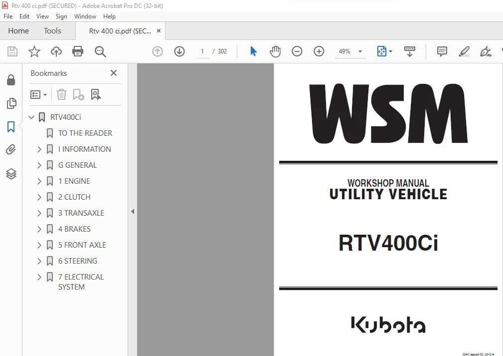
Kubota RTV400Ci Utility Vehicle Workshop Manual – PDF DOWNLOAD
Original price was: $89.95.$28.95Current price is: $28.95.
Kubota RTV400Ci Utility Vehicle Workshop Manual – PDF DOWNLOAD
Description
Kubota RTV400Ci Utility Vehicle Workshop Manual – PDF DOWNLOAD
DESCRIPTION:
Kubota RTV400Ci Utility Vehicle Workshop Manual – PDF DOWNLOAD
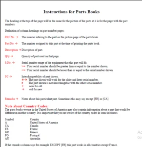
GENERAL PRECAUTIONS :
• When you disassemble, carefully put the parts in a clean area
to make it easy to find the parts. You must install the screws,
bolts and nuts in their initial position to prevent the reassembly
errors.
• When it is necessary to use special tools, use KUBOTA special
tools. Refer to the drawings when you make special tools that
you do not use frequently.
• Before you disassemble or repair machine, make sure that you
always disconnect the ground cable from the battery first.
• Remove oil and dirt from parts before you measure.
• Use only KUBOTA genuine parts for replacement to keep the
machine performance and to make sure of safety.
• You must replace the gaskets and O-rings when you assemble
again. Apply grease (1) to new O-rings or oil seals before you
assemble.
• When you assemble the external or internal snap rings, make
sure that the sharp edge (3) faces against the direction from
which force (2) is applied.
• When inserting spring pins, their splits must face the direction
from which a force is applied. See the figure left side.
• To prevent damage to the hydraulic system, use only specified
fluid or equivalent.
• Clean the parts before you measure them.
• Tighten the nipples to the specified torque. Too much torque
can cause damage to the hydraulic units or the nipples. Not
sufficient torque can cause oil leakage.
• When you use a new hose or pipe, tighten the nuts to the
specified torque. Then loosen (approx. by 45 °) and let them be
stable before you tighten to the specified torque (This is not
applied to the parts with seal tape).
• When you remove the two ends of a pipe, remove the lower end
first.
• Use two pliers in removal and installation. One to hold the stable
side, and the other to turn the side you remove to prevent twists.
• Make sure that the sleeves of flared connectors and taper s of
hoses are free of dust and scratches.
TABLE OF CONTENTS:
Kubota RTV400Ci Utility Vehicle Workshop Manual – PDF DOWNLOAD
RTV400Ci…………………………………………………………………….. 1
TO THE READER…………………………………………………………….. 2
I INFORMATION…………………………………………………………….. 3
INFORMATION…………………………………………………………… 4
1. SAFETY FIRST……………………………………………………. 5
2. SAFETY DECALS…………………………………………………… 8
3. SPECIFICATIONS………………………………………………….. 13
4. TRAVELLING SPEEDS……………………………………………….. 14
5. DIMENSIONS……………………………………………………… 15
G GENERAL………………………………………………………………… 16
GENERAL………………………………………………………………. 17
1. PRODUCT IDENTIFICATION…………………………………………… 18
2. GENERAL PRECAUTIONS……………………………………………… 19
3. HANDLING PRECAUTIONS FOR ELECTRICAL……………………………….. 20
[1] WIRING…………………………………………………….. 20
[2] BATTERY……………………………………………………. 22
[3] FUSE………………………………………………………. 22
[4] CONNECTOR………………………………………………….. 22
[5] HANDLING OF CIRCUIT TESTER…………………………………… 23
[6] COLOR OF WIRING…………………………………………….. 24
4. LUBRICANTS, FUEL AND COOLANT……………………………………… 25
5. TIGHTENING TORQUES………………………………………………. 27
[1] GENERAL USE SCREWS, BOLTS AND NUTS……………………………. 27
[2] STUD BOLTS…………………………………………………. 27
[3] HYDRAULIC FITTINGS………………………………………….. 28
(1) Hydraulic Hose Fittings………………………………….. 28
(2) Hydraulic Pipe Cap Nuts………………………………….. 28
(3) Adaptors, Elbows and Others………………………………. 28
[4] METRIC SCREWS, BOLTS AND NUTS………………………………… 29
[5] AMERICAN STANDARD SCREWS, BOLTS AND NUTS WITH UNC OR UNF THREADS…. 29
[6] PLUGS……………………………………………………… 29
6. MAINTENANCE CHECK LIST…………………………………………… 30
7. CHECK AND MAINTENANCE……………………………………………. 32
[1] DAILY CHECK………………………………………………… 32
[2] CHECK POINTS OF INITIAL 20 HOURS……………………………… 37
[3] CHECK POINTS OF INITIAL 50 HOURS……………………………… 38
[4] CHECK POINTS OF EVERY 50 HOURS……………………………….. 42
[5] CHECK POINTS OF EVERY 100 HOURS………………………………. 43
[6] CHECK POINTS OF EVERY 200 HOURS………………………………. 51
[7] CHECK POINTS OF EVERY 300 HOURS………………………………. 56
[8] CHECK POINTS OF EVERY 400 HOURS………………………………. 57
[9] CHECK POINT OF EVERY 500 HOURS……………………………….. 57
[10] CHECK POINTS OF EVERY 1 YEAR………………………………… 57
[11] CHECK POINTS OF EVERY 2 YEARS……………………………….. 58
[12] CHECK POINT OF EVERY 4 YEARS………………………………… 60
[13] OTHERS……………………………………………………. 61
8. SPECIAL TOOLS…………………………………………………… 64
[1] SPECIAL TOOLS FOR ENGINE…………………………………….. 64
[2] SPECIAL TOOLS FOR MACHINE……………………………………. 64
9. TIRES………………………………………………………….. 71
[1] TYPE OF TIRE……………………………………………….. 71
[2] TIRE PRESSURE………………………………………………. 71
[3] VEHICLE LIMITATIONS…………………………………………. 72
[4] CARGO BED………………………………………………….. 72
[5] SHOCK ABSORBERS…………………………………………….. 73
1 ENGINE…………………………………………………………………. 74
MECHANISM…………………………………………………………….. 75
1. STRUCTURE………………………………………………………. 76
2. ENGINE BODY…………………………………………………….. 78
[1] CYLINDER AND CRANKCASE………………………………………. 78
[2] MAIN BEARING COVER………………………………………….. 78
[3] CONNECTING ROD AND PISTON……………………………………. 78
[4] CRANKSHAFT…………………………………………………. 79
[5] PISTON RINGS……………………………………………….. 79
[6] CAMSHAFT…………………………………………………… 79
[7] VALVE ARRANGEMENT…………………………………………… 80
[8] CYLINDER HEAD………………………………………………. 80
[9] COOLING SYSTEM……………………………………………… 80
[10] LUBRICATING SYSTEM…………………………………………. 81
(1) Oil Pump……………………………………………….. 81
[11] TIMING CHAIN………………………………………………. 81
[12] IGNITION SYSYEM……………………………………………. 82
[13] BALANCER………………………………………………….. 82
3. FUEL SYSTEM…………………………………………………….. 83
[1] SPEED CONTROL LINKAGE……………………………………….. 84
[2] CARBON CANISTER…………………………………………….. 85
4. INTAKE SYSTEM AND EXHAUST………………………………………… 86
[1] AIR FLOW…………………………………………………… 86
[2] AIR CLEANER………………………………………………… 87
SERVICING…………………………………………………………….. 88
1. TROUBLESHOOTING…………………………………………………. 89
[1] ENGINE BODY………………………………………………… 89
[2] ELECTRONIC CONTROL FUEL INJECTION…………………………….. 92
2. SERVICING SPECIFICATIONS…………………………………………. 93
3. TIGHTENING TORQUES………………………………………………. 96
4. CHECKING AND DISASSEMBLING AND SERVICING…………………………… 98
[1] CHECKING AND ADJUSTING………………………………………. 98
(1) Compression Pressure…………………………………….. 98
(2) Valve Clearance…………………………………………. 99
(3) Fuel Pressure……………………………………………100
(4) Engine Speed…………………………………………….101
[2] DISASSSEMBLING AND ASSEMBLING…………………………………105
(1) Dismounting Engine……………………………………….105
(2) External Components………………………………………117
(3) Engine Body……………………………………………..120
[3] SERVICING…………………………………………………..127
(1) Cylinder Head and Valves………………………………….127
(2) Piston and Connecting Rod…………………………………131
(3) Cylinder………………………………………………..134
(4) Camshaft………………………………………………..134
(5) Timing chain…………………………………………….135
(6) Crankshaft and Connecting Rod……………………………..135
(7) Oil Pump………………………………………………..136
2 CLUTCH………………………………………………………………….137
MECHANISM……………………………………………………………..138
1. CLUTCH SYSTEM……………………………………………………139
[1] CLUTCH OPERATION…………………………………………….140
[2] ONE WAY CLUTCH OPERATION (ENGINE BRAKE)………………………..141
SERVICING……………………………………………………………..142
1. TROUBLESHOOTING………………………………………………….143
2. SERVICING SPECIFICATIONS………………………………………….144
3. TIGHTENING TORQUES……………………………………………….145
4. DISASSEMBLING AND SERVICING……………………………………….146
[1] DISASSEMBLING AND ASSEMBLING………………………………….146
[2] SERVICING…………………………………………………..148
3 TRANSAXLE……………………………………………………………….149
MECHANISM……………………………………………………………..150
1. STRUCTURE……………………………………………………….151
2. POWER TRAIN……………………………………………………..152
[1] CVT (CONTINUOUSLY VARIABLE TRANSMISSION) SECTION………………..152
[2] RANGE GEAR SHIFT SECTION……………………………………..153
[3] FRONT WHEEL DRIVE SECTION…………………………………….155
[4] REAR AXLE SECTION……………………………………………156
3. REAR SUSPENSION………………………………………………….157
SERVICING……………………………………………………………..158
1. TROUBLESHOOTING………………………………………………….159
[1] GENERAL…………………………………………………….159
[2] TRAVELLING GEAR SHIFT SECTION…………………………………159
[3] DIFFERENTIAL GEAR SECTION…………………………………….160
2. SERVICING SPECIFICATIONS………………………………………….161
3. TIGHTENING TORQUES……………………………………………….162
4. CHECK, DISASSEMBLING AND SERVICING…………………………………163
[1] CHECKING AND ADJUSTING……………………………………….163
[2] DISASSEMBLING AND ASSEMBLING………………………………….167
(1) Replace the CVT Belt……………………………………..167
(2) Dismounting Transaxle and Engine…………………………..171
5. SERVICING……………………………………………………….186
4 BRAKES………………………………………………………………….189
MECHANISM……………………………………………………………..190
1. GENERAL OUTLINE………………………………………………….191
2. FRONT BRAKE……………………………………………………..192
3. REAR BRAKE………………………………………………………193
4. MASTER CYLINDER………………………………………………….194
5. BRAKE OIL……………………………………………………….195
6. PARKING BRAKE……………………………………………………196
SERVICING……………………………………………………………..197
1. TROUBLESHOOTING………………………………………………….198
2. SERVICING SPECIFICATIONS………………………………………….200
3. TIGHTENING TORQUES……………………………………………….201
4. CHECKING, DISASSEMBLING AND SERVICING………………………………202
[1] CHECKING AND ADJUSTING……………………………………….202
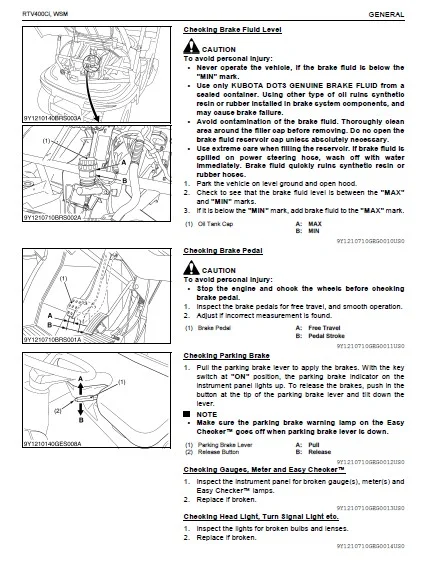
(1) Brake Pedal……………………………………………..202
(2) Brake Fluid……………………………………………..203
(3) Brake Pad……………………………………………….206
(4) Parking Brake Lever………………………………………207
[2] DISASSEMBLING AND ASSEMBLING………………………………….210
(1) Removing the Front Brake Assembly………………………….210
(2) Separating the Knuckle Case and Brake Disc………………….211
(3) Removing the Rear Brake Assembly…………………………..213
(4) Removing Master Cylinder Assembly………………………….215
(5) Front Brake Pad………………………………………….215
(6) Front Brake Disc…………………………………………217
(7) Rear Brake Pad…………………………………………..218
(8) Rear Brake Disc………………………………………….220
(9) Brake Master Cylinder…………………………………….223
[3] SERVICING…………………………………………………..224
(1) Brake Pad……………………………………………….224
(2) Brake Disc………………………………………………224
5 FRONT AXLE………………………………………………………………225
MECHANISM……………………………………………………………..226
1. STRUCTURE……………………………………………………….227
[1] FRONT AXLE………………………………………………….227
[2] FRONT SUSPENSION…………………………………………….228
SERVICING……………………………………………………………..229
1. TROUBLESHOOTING………………………………………………….230
2. SERVICING SPECIFICATIONS………………………………………….231
3. TIGHTENING TORQUES……………………………………………….232
4. CHECKING, DISASSEMBLING AND SERVICING………………………………233
[1] CHECKING AND ADJUSTING……………………………………….233
[2] DISASSEMBLING AND ASSEMBLING………………………………….234
(1) Separating Front Differential Case…………………………234
(2) Separating Front Suspension……………………………….237
(3) Front Differential Case…………………………………..240
(4) Strut…………………………………………………..242
[3] SERVICING…………………………………………………..243
6 STEERING………………………………………………………………..249
MECHANISM……………………………………………………………..250
1. STRUCTURE……………………………………………………….251
[1] STEERING LINKAGE…………………………………………….251
[2] MANUAL STEERING……………………………………………..252
SERVICING……………………………………………………………..253
1. TROUBLESHOOTING………………………………………………….254
2. TIGHTENING TORQUES……………………………………………….255
3. DISASSEMBLING AND SERVICING……………………………………….256
[1] PREPARATION…………………………………………………256
(1) Steering Assembly………………………………………..256
(2) Steering Linkage…………………………………………257
[2] DISASSEMBLING AND ASSEMBLING………………………………….258
[3] SERVICING…………………………………………………..258
7 ELECTRICAL SYSTEM………………………………………………………..259
MECHANISM……………………………………………………………..260
1. WIRING DIAGRAM…………………………………………………..261
2. STARTING SYSTEM………………………………………………….262
[1] STARTER MOTOR……………………………………………….263
(1) Structure……………………………………………….263
(2) Operating Principle………………………………………264
[2] SAFETY SWITCH……………………………………………….265
3. CHARGING SYSTEM………………………………………………….266
[1] CHARGE COIL…………………………………………………267
[2] REGULATOR…………………………………………………..267
4. LIGHTING SYSTEM………………………………………………….268
5. GAUGES………………………………………………………….269
[1] ENGINE CASE TEMPERATURE………………………………………270
[2] TRAVELING SPEED (ROTATION) SENSOR (OPTION)……………………..270
[3] EASY CHECKER™……………………………………………….271
6. ELECTRIC FUEL INJECTION SYSTEM…………………………………….273
SERVICING……………………………………………………………..276
1. TROUBLESHOOTING………………………………………………….277
[1] ELECTRONIC CONTROL FUEL INJECTION……………………………..277
[2] GENERAL…………………………………………………….277
2. SERVICING SPECIFICATIONS………………………………………….280
3. TIGHTENING TORQUES……………………………………………….281
4. CHECKING, DISASSEMBLING AND SERVICING………………………………282
[1] CHECKING AND ADJUSTING……………………………………….282
(1) Battery…………………………………………………282
(2) Main Switch……………………………………………..284
(3) Spark Plug………………………………………………285
(4) Starter…………………………………………………285
(5) Safety Switch……………………………………………286
(6) Relays………………………………………………….287
(7) Charging System………………………………………….287
(8) Lighting System………………………………………….288
(9) EFI System………………………………………………292
[2] DISASSEMBLING AND ASSEMBLING………………………………….298
(1) Starter…………………………………………………298
[3] SERVICING…………………………………………………..300
(1) Starter…………………………………………………300
IMAGES PREVIEW OF THE MANUAL:
KUBOTA RTV400CI UTILITY VEHICLE WORKSHOP MANUAL – PDF DOWNLOAD:
PLEASE NOTE:
- This is the SAME exact manual used by your dealers to fix your vehicle.
- The same can be yours in the next 2-3 mins as you will be directed to the download page immediately after paying for the manual.
- Any queries / doubts regarding your purchase, please feel free to contact [email protected]
S.V